 Open Access Article
La2O3-coated Li2ZnTi3O8@C as a high performance anode for lithium-ion batteries†
Zhaohui Menga,
Suhong Wanga,
Hongwei Wanga,
Lijuan Wang *b and
Song Wang*b
aCollege of Chemistry and Pharmaceutical Engineering, Nanyang Normal University, Nanyang 473061, China
bSchool of Chemistry and Material Science, Liaoning Shihua University, Fushun 113001, Liaoning, China. E-mail: lijuanw123@163.com; Tel: +86-24-56861711
First published on 2nd July 2019
Abstract
Li2ZnTi3O8C@La2O3 (LZTO@C@La2O3) coated with composite protective layers is successfully fabricated via a facile solid-state route. The co-coating strategy greatly improves the electrochemical performance of LZTO. 89.8%, 77.2% and 76.7% of the discharge specific capacities for the 2nd cycle can be retained at the 200th cycle at 1, 2 and 3 A g−1, respectively. At 4 and 5 A g−1, 174.3 and 166.1 are still retained for the 100th cycle, respectively. Even at a high temperature of 55 °C, LZTO@C@La2O3 still has good cycling performance. The excellent electrochemical performance is due to the stable surface structure between LZTO and the electrolyte, a good conductive network, small particle size, and large specific surface area as well as pore volume.
Introduction
Lithium-ion batteries (LIBs) have been widely used in portable electronics and considered as promising power sources for hybrid electric vehicles (HEVs) as well as electric vehicles (EVs) since they were commercialized in the early 1990s.1,2 In commercial LIBs, graphite is the main anode material. However, the carbon material suffers from poor rate capability and safety originating from the formation of lithium dendrites owing to its low Li-intercalation potential close to 0 V (vs. Li/Li+).3 To solve these problems, the spinel Li4Ti5O12 (LTO) with good rate capability and safety, has been developed as a new commercial candidate.4 Nevertheless, its small theoretical specific capacity (175 mA h g−1) restricts it from being widely used in LIBs with high energy density. Therefore, many new anode materials with large specific capacities, including metallic oxides,5–9 alloy compounds10–12 and Si-based materials,13,14 have been researched. Unfortunately, the large volume expansion severely deteriorates the cycling performance of the materials mentioned above. So, it is urgent to find an anode material with good safety, acceptable specific capacity and small volume change.In recent, spinel structure Li2ZnTi3O8 (LZTO) with the space group of P4332 has received much attention as an appealing anode for various advantages:15–19 (1) the main Li-intercalation potential is ca. 0.5 V which can prevent the growth of the dendritic lithium and ensure the good safety for LZTO. (2) Compared with the theoretical specific capacity of LTO, the value of LZTO (229 mA h g−1) increases by 30%. (3) Similar to LTO, the LZTO shows zero volume change which can benefit the cyclic performance. (4) The three-dimensional network constructed by LiO6 and TiO6 octahedrons is beneficial to Li+ diffusion. (5) The preparation of LZTO is low cost, simpleness and environment friendly, so it is proper for large-scale production.
Even so, the low electronic conductivity of LZTO results in its poor rate capability. Many methods have been adopted to solve the problem, such as synthesizing nano-sized LZTO,20,21 coating conductive agents22,23 and doping with metal ions.24–27 The rate capability of LZTO has been improved via the three ways above. Moreover, LZTO has good cyclic performance as a zero-strain material theoretically. In fact, its cyclic performance is unsatisfactory due to the dissolution of transition metal elements in LZTO attacked by HF from the lithium salt LiPF6 in the electrolyte. Surface coating has been considered as an effective method of solving the issue.28–31 Tang et al.29 synthesized Li2ZnTi3O8/La2O3 with good cyclic performance. Nevertheless, the rate capability of Li2ZnTi3O8/La2O3 should be greatly improved. At 3 A g−1, its discharge specific capacity is only 149.3 mA h g−1.
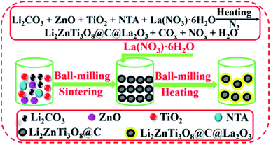
Herein, we firstly report the fabrication of Li2ZnTi3O8@C@La2O3 co-coated with carbon and La2O3 by a simple solid-state route using nitrilotriacetic acid (NTA) as the carbon source (Fig. 1). The electronic conductivity can be greatly enhanced due to the existence of carbon, which will benefit its rate capability. The carbon and La2O3 as co-coating layers can suppress the dissolution of the surface metal ions from LZTO and then improve the cyclic performance.
Experimental
Synthesis of Li2ZnTi3O8@C@La2O3 and Li2ZnTi3O8@C
The Li2ZnTi3O8@C@La2O3 anode was fabricated by a two-step solid-state route. Li2CO3, ZnO, TiO2 and NTA were dispersed in ammonium hydroxide (9 wt%) and ball-milled for 5 h in the molar ratio of 1.1![[thin space (1/6-em)]](https://www.rsc.org/images/entities/char_2009.gif) :
:![[thin space (1/6-em)]](https://www.rsc.org/images/entities/char_2009.gif) 1
1![[thin space (1/6-em)]](https://www.rsc.org/images/entities/char_2009.gif) :
:![[thin space (1/6-em)]](https://www.rsc.org/images/entities/char_2009.gif) 3
3![[thin space (1/6-em)]](https://www.rsc.org/images/entities/char_2009.gif) :
:![[thin space (1/6-em)]](https://www.rsc.org/images/entities/char_2009.gif) 2. The Li salt can volatilize in sintering process at high temperature. So, the Li source is slight excess. The mixture was dried at 90 °C and then sintered at 700 °C for 3 h in N2. The obtained product was ball-milled with La(NO3)3·6H2O for 5 h with the mass ratio of 1
2. The Li salt can volatilize in sintering process at high temperature. So, the Li source is slight excess. The mixture was dried at 90 °C and then sintered at 700 °C for 3 h in N2. The obtained product was ball-milled with La(NO3)3·6H2O for 5 h with the mass ratio of 1![[thin space (1/6-em)]](https://www.rsc.org/images/entities/char_2009.gif) :
:![[thin space (1/6-em)]](https://www.rsc.org/images/entities/char_2009.gif) 0.0935. The mixture was dried at 90 °C and then heated at 550 °C for 3 h in N2. The obtained material was denoted as Li2ZnTi3O8@C@La2O3 (LZTO@C@La2O3). The same processes were used to synthesize Li2ZnTi3O8@C (LZTO@C) without La(NO3)3·6H2O and post-treatment at 550 °C for 3 h in N2.
0.0935. The mixture was dried at 90 °C and then heated at 550 °C for 3 h in N2. The obtained material was denoted as Li2ZnTi3O8@C@La2O3 (LZTO@C@La2O3). The same processes were used to synthesize Li2ZnTi3O8@C (LZTO@C) without La(NO3)3·6H2O and post-treatment at 550 °C for 3 h in N2.
Physical and electrochemical performance measurements
The detailed measurements were shown in ESI.†Results and discussion
The diffraction peaks of LZTO@C and LZTO@C@La2O3 can be well attributed to the spinel LZTO (JCPDS# 86-1512) (Fig. 2a), indicating that the crystal structure of LZTO is not altered in the existence of carbon and La2O3. The lattice parameters of LZTO@C@La2O3 are slightly larger than those of LZTO@C (Table S1†) due to the extra post-treatment at 550 °C for 3 h in N2 for LZTO@C@La2O3. Moreover, the diffraction peaks of LZTO@C@La2O3 have no apparent shift in contrast with the patterns of LZTO@C (Fig. 2a and b). These indicate that the La element is not doped into the crystal lattice but coated on the surface of LZTO particles in the form of La2O3. The XPS data further confirm that the La element exists in the form of La2O3 in LZTO@C@La2O3 (Fig. S1a and b†). The content of La2O3 is ca. 3 wt% in LZTO@C@La2O3 calculated from the ICP result. However, there are no diffraction peaks related to La2O3 are observed. It is possible that the content of La2O3 is low or the La2O3 coating layer is thin. The XPS spectra show that there is carbon in LZTO@C and LZTO@C@La2O3 (Fig. S1a, c and d†). The carbon content is ca. 11.5 wt% for LZTO@C and LZTO@C@La2O3 (Fig. S2†). Nevertheless, the carbon is not detected from the XRD results. It may be that the carbon is amorphous.32,33 The superficial electronic conductivity of LZTO can be greatly enhanced due to the existence of carbon. The carbon and La2O3 co-coating layers can prevent the direct contact between LZTO and electrolyte, and then some side reactions can be weakened on the interface.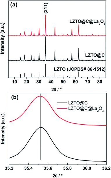 | ||
| Fig. 2 (a) X-ray diffraction patterns and (b) magnified (311) peaks of the LZTO@C and LZTO@C@La2O3 anodes. | ||
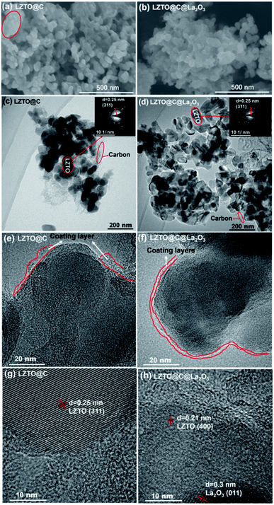
The LZTO@C particles are interconnected to each other. However, some of them are aggregated together marked by the circle (Fig. 3a). The LZTO@C@La2O3 is agglomerates of tiny particles (Fig. 3b). There is carbon in LZTO@C and LZTO@C@La2O3 from the TEM images and the EDX results (Fig. 3c–f and S3†). Compared with LZTO@C, the LZTO@C@La2O3 particles can be more homogeneously coated (Fig. 3e and f). La element is also investigated from EDX spectroscopy and uniformly dispersed onto the LZTO@C@La2O3 (Fig. S3†). The HRTEM image further indicates that the La element in the form of La2O3 exists in LZTO@C@La2O3 (Fig. 3h). Compared with LZTO@C, the carbon and La2O3 co-coating layers make LZTO@C@La2O3 have smaller particle size of 36 nm and then larger specific surface area of 72.8 m2 g−1 (Fig. S3j, k, S4 and Table S2†), which can increase the contact area between LZTO@C@La2O3 particles and electrolyte, and then will improve the reversible capacity. In addition, LZTO@C@La2O3 has larger total pore volume and average pore diameter in contrast with LZTO@C (Fig. S4 and Table S2†). The small particle size and large pore can speed the diffusion of Li+ ions and then will benefit the rate capability of LZTO@C@La2O3.
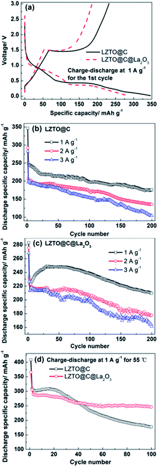
The initial galvanostatic charge–discharge profiles are depicted in Fig. 4a at 1 A g−1 in 0.02–3 V for LZTO@C and LZTO@C@La2O3. For the two samples, there is a charge plateau at ca. 1.45 V and two discharge plateaus at ca. 1.03 and 0.42 V on the curves with two-step intercalation of Li+ ions, based on the Ti4+/Ti3+ redox couple.24 The electrochemical reaction mechanisms were also confirmed via the cyclic voltammetry (CV) measurements (Fig. S5 and Table S3†). The one anodic peak and two cathodic peaks correspond to the one charge plateau and two discharge plateaus for the two samples, respectively. Compared with LZTO@C@La2O3, the discharge specific capacity (346.5 mA h g−1) is larger and the coulombic efficiency (67%) is higher for LZTO@C at the 1st cycle (Table 1). The poor electrochemical performance of LZTO@C@La2O3 at the 1st cycle is owing to the following reasons: (1) the specific capacity is calculated based on the mass of LZTO@C@La2O3. The mass ratio of La2O3 is ca. 3 wt%. The existence of inactive La2O3 lowers the specific capacity of LZTO@C@La2O3. (2) The La2O3 coating layer increases the resistance of LZTO@C@La2O3/Li (Fig. S6 and Table S4†). The polarization increases during insertion and deinsertion of Li+ ions (Fig. S5 and Table S3†). However, LZTO@C@La2O3 has larger specific capacities in contrast with LZTO@C after 11 cycles at 1 A g−1 (Fig. 4b and c). It is because the internal resistance and polarization decrease for the LZTO@C@La2O3/Li in the subsequent cycling process (Fig. S7†), and then the diffusion paths of Li+ ions become smooth. At the 200th cycle, the capacity retention is 70.5% and 89.8% corresponding to the 2nd cycle for LZTO@C and LZTO@C@ La2O3, respectively (Table 2).
| Samples | Discharge specific capacity (mA h g−1) | Coulombic efficiency |
|---|---|---|
| LZTO@C | 346.5 | 67% |
| LZTO@C@La2O3 | 283 | 65.4% |
| Current density (A g−1) | LZTO@C | LZTO@C@La2O3 | ||
|---|---|---|---|---|
| Specific capacity (mA h g−1) | Capacity retention | Specific capacity (mA h g−1) | Capacity retention | |
| 1 | 249.7 | 70.5% | 233.4 | 89.8% |
| 2 | 206.7 | 65.7% | 230.2 | 77.2% |
| 3 | 196.9 | 52.8% | 210.6 | 76.7% |
Compared with LZTO@C, LZTO@C@La2O3 has smaller initial discharge specific capacities but better cyclic performance at 2 and 3 A g−1 (Fig. 4b, c and Table 2). After 200 cycles, the capacity retention based on the 2nd cycle is 77.2% and 76.7% for LZTO@C@La2O3 at 2 and 3 A g−1, respectively. The retention is 65.7% and 52.8% for LZTO@C at 2 and 3 A g−1, respectively. At 55 °C, the LZTO@C@La2O3 still has better cyclic performance (Fig. 4d). After 100 cycles, 57.5% and 80.6% of the capacities for the 2nd cycle can be kept for LZTO@C and LZTO@C@La2O3, respectively. Its cyclic performance exceeds many previous reports (Table S5†). The enhanced cyclic performance for LZTO@C@La2O3 is attributed to the following reasons: (1) there is some HF in the commercial electrolyte. It can result in the dissolution of transition metal elements for the LZTO electrode, leading to capacity decay.34,35 The carbon and La2O3 co-coating layers can prevent LZTO directly contacting with electrolyte. In addition, La2O3 can react with HF. These can weaken the attract from HF to active material LZTO. The mechanism is shown in Fig. S8† in detail. (2) The integrity of LZTO@C@La2O3 electrode can be well kept and good electrical contact can be obtained during cycling process (Fig. S9b and d†).
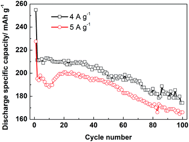
Moreover, the LZTO@C@La2O3 exhibits good rate capability. The discharge specific capacities are 211.4 and 195.3 mA h g−1 at 4 and 5 A g−1 for the 2nd cycle, respectively. Cycling for 100 cycles, 174.3 and 166.1 mA h g−1 are still kept, respectively (Fig. 5). Its rate capability exceeds many previous reports (Table S6†), which may be due to the reasons below: (1) the carbon coating layer can enhance the superficial electronic conductivity of LZTO. (2) The existence of carbon and La2O3 co-coating layers makes LZTO have small particle size, large specific surface area and pore size. (3) The presence of carbon and La2O3 makes good adhesion between LZTO and Cu current collector and then good conductive network is formed (Fig. S9b–d†).
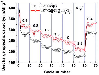
The cyclic data of LZTO@C and LZTO@C@La2O3 at different current densities are exhibited in Fig. 6. Compared with LZTO@C, LZTO@C@La2O3 has smaller initial discharge specific capacity at low current density of 0.4 A g−1. However, discharge specific capacities of LZTO@C@La2O3 exceed those of LZTO@C at different current densities in the subsequently cycling process. The discharge specific capacities are ca. 280 and 315 mA h g−1 for LZTO@C and LZTO@C@La2O3 at 0.4 A g−1, respectively. When the current density was reset to 0.4 A g−1 after cycling for 60 cycles at different current densities, ca. 285 and 325 mA h g−1 are obtained for LZTO@C and LZTO@C@La2O3, respectively. Good cyclic reversibility is obtained for the two samples. In addition, the two electrodes are activated after cycling at 0.4 A g−1,26 so large capacities are obtained in the subsequent cycling process.
Conclusions
Li2ZnTi3O8@C@La2O3 co-coated with carbon and La2O3 has been successfully fabricated via a simple solid-state route. The carbon can improve the electronic conductivity, which benefits its rate capability. The carbon and La2O3 co-coating layers can suppress the dissolution transition metal elements and then greatly improve the cyclic performance. In addition, the co-coating layers make LZTO have large specific surface area as well as pore size, and make LZTO@C@La2O3 electrode form good conductive network, which can improve its electrochemical performance. The designed LZTO@C@La2O3 composite material exhibits good cyclic performance and high rate capability. In consideration of the facile synthetic route and remarkable electrochemical performance, LZTO@C@La2O3 coated with composite protective layers is thought to be a promising anode of LIBs.Conflicts of interest
There are no conflicts to declare.Acknowledgements
We thank for the support from the Henan Joint Funds of the National Natural Science Foundation of China (U1504532) and the Natural Science Foundation of Liaoning Shihua University (2018XJJ-012).Notes and references
- D. Chen, Z. Lou, K. Jiang and G. Shen, Adv. Funct. Mater., 2018, 28, 1805596 CrossRef.
- T. Kim, W. Song, D.-Y. Son, L. K. Ono and Y. Qi, J. Mater. Chem. A, 2019, 7, 2942–2964 RSC.
- M. Salah, P. Murphy, C. Hall, C. Francis, R. Kerr and M. Fabretto, J. Power Sources, 2019, 414, 48–67 CrossRef CAS.
- C. Han, Y.-B. He, M. Liu, B. Li, Q.-H. Yang, C.-P. Wong and F. Kang, J. Mater. Chem. A, 2017, 5, 6368–6381 RSC.
- H. Chen, J. He, Y. Li, S. Luo, L. Sun, X. Ren, L. Deng, P. Zhang, Y. Gao and J. Liu, J. Mater. Chem. A, 2019, 7, 7691–7700 RSC.
- S. Jia, Y. Wang, X. Liu, S. Zhao, W. Zhao, Y. Huang, Z. Li and Z. Lin, Nano Energy, 2019, 59, 229–236 CrossRef CAS.
- Q. Feng, H. Li, Z. Tan, Z. Huang, L. Jiang, H. Zhou, H. Pan, Q. Zhou, S. Ma and Y. Kuang, J. Mater. Chem. A, 2018, 6, 19479–19487 RSC.
- W. Zhang, Y. Fu, W. Liu, L. Lim, X. Wang and A. Yu, Nano Energy, 2019, 57, 48–56 CrossRef CAS.
- T. Herdt, D. Deckenbach, M. Bruns and J. J. Schneider, Nanoscale, 2019, 11, 598–610 RSC.
- W. Qi, J. G. Shapter, Q. Wu, T. Yin, G. Gao and D. Cui, J. Mater. Chem. A, 2017, 5, 19521–19540 RSC.
- K.-H. Nam, G.-K. Sung, J.-H. Choi, J.-S. Youn, K.-J. Jeon and C.-M. Park, J. Mater. Chem. A, 2019, 7, 3278–3288 RSC.
- Z. Yi, Z. Wang, Y. Cheng and L. Wang, Energy Environ. Mater., 2018, 1, 132–147 CrossRef CAS.
- Y. Son, J. Ma, N. Kim, T. Lee, Y. Lee, J. Sung, S. H. Choi, G. Nam, H. Cho, Y. Yoo and J. Cho, Adv. Energy Mater., 2019, 9, 1803480 CrossRef.
- K. Feng, M. Li, W. Liu, A. G. Kashkooli, X. Xiao, M. Cai and Z. Chen, Small, 2018, 14, 1702737 CrossRef PubMed.
- Z. Hong, X. Zheng, X. Ding, L. Jiang, M. Wei and K. Wei, Energy Environ. Sci., 2011, 4, 1886 RSC.
- H. Tang, Q. Weng and Z. Tang, Electrochim. Acta, 2015, 151, 27–34 CrossRef CAS.
- L. Wang, L. Wu, Z. Li, G. Lei, Q. xiao and P. Zhang, Electrochim. Acta, 2011, 56, 5343–5346 CrossRef CAS.
- X. Li, L. Wang, C. Li, B. Chen, Q. Zhao and G. Zhang, J. Power Sources, 2016, 308, 65–74 CrossRef CAS.
- X. Li, Q. Xiao, B. Liu, H. Lin and J. Zhao, J. Power Sources, 2015, 273, 128–135 CrossRef CAS.
- Z. Hong, M. Wei, X. Ding, L. Jiang and K. Wei, Electrochem. Commun., 2010, 12, 720–723 CrossRef CAS.
- L. Wang, Z. Meng, H. Wang, X. Li and G. Zhang, Ceram. Int., 2016, 42, 16872–16881 CrossRef CAS.
- C. Chen, C. Ai, X. Liu, Y. He, S. Yang and Y. Wu, J. Alloys Compd., 2017, 698, 692–698 CrossRef CAS.
- Z. Meng, L. Wang, X. Li, G. Zhang and H. Li, Int. J. Hydrogen Energy, 2017, 42, 2177–2186 CrossRef CAS.
- C. Chen, C. Ai, X. Liu and Y. Wu, Electrochim. Acta, 2017, 227, 285–293 CrossRef CAS.
- H. Li, Z. Li, X. Liang, J. Ouyang, Y. Ma, Y. Cui, C. Ma and Z. Tang, Mater. Lett., 2017, 192, 128–132 CrossRef CAS.
- S. Wang, Y. Bi, L. Wang, Z. Meng and B. Luo, Electrochim. Acta, 2019, 301, 319–324 CrossRef CAS.
- T.-F. Yi, J.-Z. Wu, J. Yuan, Y.-R. Zhu and P.-F. Wang, ACS Sustainable Chem. Eng., 2015, 3, 3062–3069 CrossRef CAS.
- Z. Li, H. Li, Y. Cui, Z. Du, Y. Ma, C. Ma and Z. Tang, J. Alloys Compd., 2017, 692, 131–139 CrossRef CAS.
- H. Tang, L. Zan, J. Zhu, Y. Ma, N. Zhao and Z. Tang, J. Alloys Compd., 2016, 667, 82–90 CrossRef CAS.
- H. Yang, X.-H. Wang, Y.-X. Qi, N. Lun, Y.-M. Cao and Y.-J. Bai, ACS Sustainable Chem. Eng., 2017, 5, 6099–6106 CrossRef CAS.
- H. Tang, J. Zhu, C. Ma and Z. Tang, Electrochim. Acta, 2014, 144, 76–84 CrossRef CAS.
- C. Chen, C. Ai, Y. He, S. Yang and Y. Wu, J. Alloys Compd., 2017, 705, 438–444 CrossRef CAS.
- Y. Ren, P. Lu, X. Huang, J. Ding and H. Wang, RSC Adv., 2016, 6, 49298–49306 RSC.
- H. Tang, Y. Zhou, L. Zan, N. Zhao and Z. Tang, Electrochim. Acta, 2016, 191, 887–894 CrossRef CAS.
- H. Tang, L. Zan, W. Mao and Z. Tang, J. Electroanal. Chem., 2015, 751, 57–64 CrossRef CAS.
Footnote |
| † Electronic supplementary information (ESI) available. See DOI: 10.1039/c9ra03846a |
| This journal is © The Royal Society of Chemistry 2019 |

