
 Open Access Article
 This Open Access Article is licensed under a Creative Commons Attribution-Non Commercial 3.0 Unported Licence
A hybrid YSZ/SnO2/MEMS SO2 gas sensor
Ting-Jen Hsueh *a and
Chun-Liang Lub
*a and
Chun-Liang Lub
aDepartment of Electronic Engineering, National Kaohsiung University of Science and Technology, Kaohsiung 807, Taiwan. E-mail: tj.hsueh@gmail.com
bInstitute of Microelectronics, Department of Electrical Engineering, National Cheng Kung University, Tainan 701, Taiwan
First published on 4th September 2019
Abstract
This study uses a solid YSZ electrolyte film in a SnO2 MEMS SO2 gas sensor of the semiconductor type to enhance the redox reaction. The YSZ film is prepared by RF sputtering. XRD analysis shows the presence of the (111), (200), (220) and (311) peaks that denote the crystallization planes of YSZ. The experimental results show that the SnO2 MEMS SO2 gas sensor with a YSZ film has a better sensor response than a pure SnO2 MEMS SO2 gas sensor or a YSZ MEMS SO2 gas sensor when the SO2 concentration and the sensor's temperature sensors are 250 ppb and 400 °C, respectively. The YSZ/SnO2 sensor's measured responses are around 6%, 45%, 20% and 16% when the sensor is respectively operated at 250 °C, 300 °C, 350 °C, and 400 °C.
Introduction
As technological advances and industrial development are becoming more rapid in the petrochemical industry, environmental pollution has become an important issue. The types of air pollutants include nitrogen oxides (NOx), sulfur oxides (SOx) and PM2.5 (particulate matter with a diameter of 2.5 μm or less).1 SOx causes acid rain, soil acidification and climate change.2 SOx become PM2.5 when molecules of SOx react with basic compounds in the atmosphere.2,3 In the family of SOx (such as SO, SO2, SO3 etc.), sulfur dioxide (SO2) is a major component, and is usually the indicator that is used for SOx monitoring.4 SO2 is one of the most toxic substances known. It is known that toxic gases are hazardous to human health.Over the past decade, toxic gases have been detected using electrochemical, catalytic bead, photoionization, infrared point and semiconductor devices. The electrochemical type can be divided into those that use liquid electrolytes or solid-state electrolytes. Solid electrolytes are widely studied because they are accurate and reliable, small and light, flexible to install and easy to use.5 Yttria stabilized zirconia (YSZ) devices have high chemical and thermo mechanical stability.6 For thick film applications, the operating temperature of the YSZ is more than 600 °C.6
Recently, the authors reported a SnO2 micro-electro mechanical systems (MEMS) gas sensor.7 Semiconducting metal oxide MEMS gas sensors have a number of advantages in terms of use in consumer devices, such as low cost, high efficiency, high integration, low power consumption, high sensitivity and being well suited to wearable applications. They are potentially compatible with silicon microelectronics. The oxygen-related gas-sensing mechanism involves the absorption of oxygen molecules on the oxide surface to generate chemisorbed oxygen species (O2−, O2−, O−) by capturing electrons from the conductance band, which makes the oxide surface highly resistive. The oxide is exposed to traces of the reductive gas. In reacting with the oxygen species at the oxide surface, the reductive gas reduces the concentration of the oxygen species on this surface and thereby increases the electron concentration.8 However, SO2 molecules have an indistinctive redox reaction.3
To sense SO2 molecules and to increase energy savings, this study uses a solid electrolyte YSZ film in a SnO2 MEMS structure to form a MEMS SO2 gas sensor. The properties of the fabricated sensors are also determined. The sensing properties of the YSZ thin film SO2 gas sensor are determined.
Experimental
Fig. 1(a) schematically depicts the processing steps for the YSZ/SnO2 MEMS SO2 gas sensor and Fig. 1(b) shows the structure of the YSZ/SnO2 MEMS SO2 gas sensor. The structure comprises a suspension, an isolation layer, a micro heater and a sensing material. The micro heater provides a heat source that generates temperatures up to 450 °C. Recently, the authors reported the fabrication of a MEMS SO2 gas sensor structure.9 This study uses a different micro heater material, interdigital transducer (IDT) electrode (Ni/Cr) and sensing film (YSZ/SnO2). Prior to the fabrication of an YSZ/SnO2 MEMS SO2 gas sensor, a 6 inch Si wafer was thermally oxidized to form a 700 nm-thick SiO2 film. Standard photolithography was used to define the micro heater and the IDT electrode and a 50 nm thick Cr adhesion layer was deposited on a SiO2/Si substrate. A 300 nm Ni film was then deposited on the Cr/SiO2/Si substrate using electron gun evaporation. A 400 nm SiO2 was deposited on the micro heater using PECVD.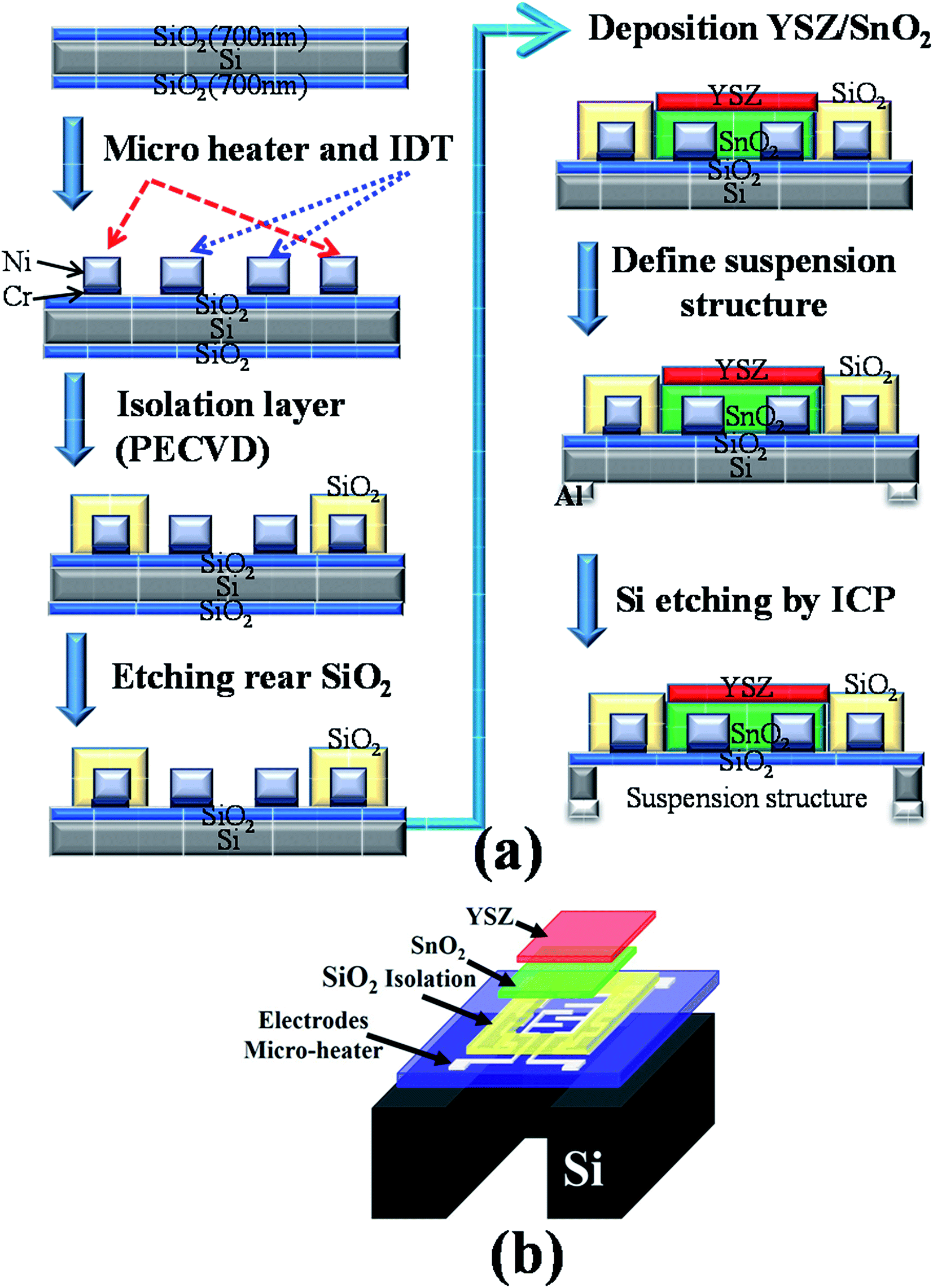 | ||
| Fig. 1 (a) A schematic diagram of the processing steps for the YSZ/SnO2 MEMS SO2 gas sensor and (b) the structure of the YSZ/SnO2 MEMS SO2 gas sensor. | ||
For the sensor film, a 600 nm thick SnO2 layer and a 300 nm thick YSZ layer were deposited by sputtering. Acetone was used to remove the positive type photoresist. Finally, on the reverse side, a 200 nm thick Al layer was then deposited as the etching barrier layer by sputtering. Standard photolithography was used to make a mask to etch the Al layer. Acetone was used to remove the positive-type photoresist and the exposed Al was then wet-etched using aluminum etch. For the DRIE process, the flow rates for SF6 gas and O2 gas, the substrate temperature, the etching time, the electrode gap, the RF power and the chamber pressure were set at 6.3 sccm, 70 sccm, −120 °C, 210 min, 7 cm, 1000 W, and 10 mTorr, respectively.
The thermal image and morphology were measured using a thermal imaging camera and field-emission scanning electron microscopy (FESEM, JEOL JSM-7000F). The crystallographic properties of the as-grown samples were then determined using X-ray diffraction (XRD; MXP18, and MAC Science) measurements. The resulting gas sensor was then electronically characterized using a Keithley 2400 source meter and a personal computer.
Results and discussion
Fig. 2(a) shows the top view SEM images of the YSZ/SnO2 MEMS SO2 gas sensor. It is found that the morphology of the surface is the same as that in Fig. 1(b). Fig. 2(b) shows the top optical microscopy image of the YSZ/SnO2 MEMS SO2 gas sensor. It was found that the annular micro-heater surrounds the finger-like electrodes. The inset of Fig. 2(a) shows an enlarged image of the sensing film (green dotted circle). It is seen that the YSZ has a uniform grain size, with a diameter of about 50 nm. It is also seen that there is a gap between each grain of at most 20 nm. These interfaces create oxygen diffusion pathways for gas sensing.10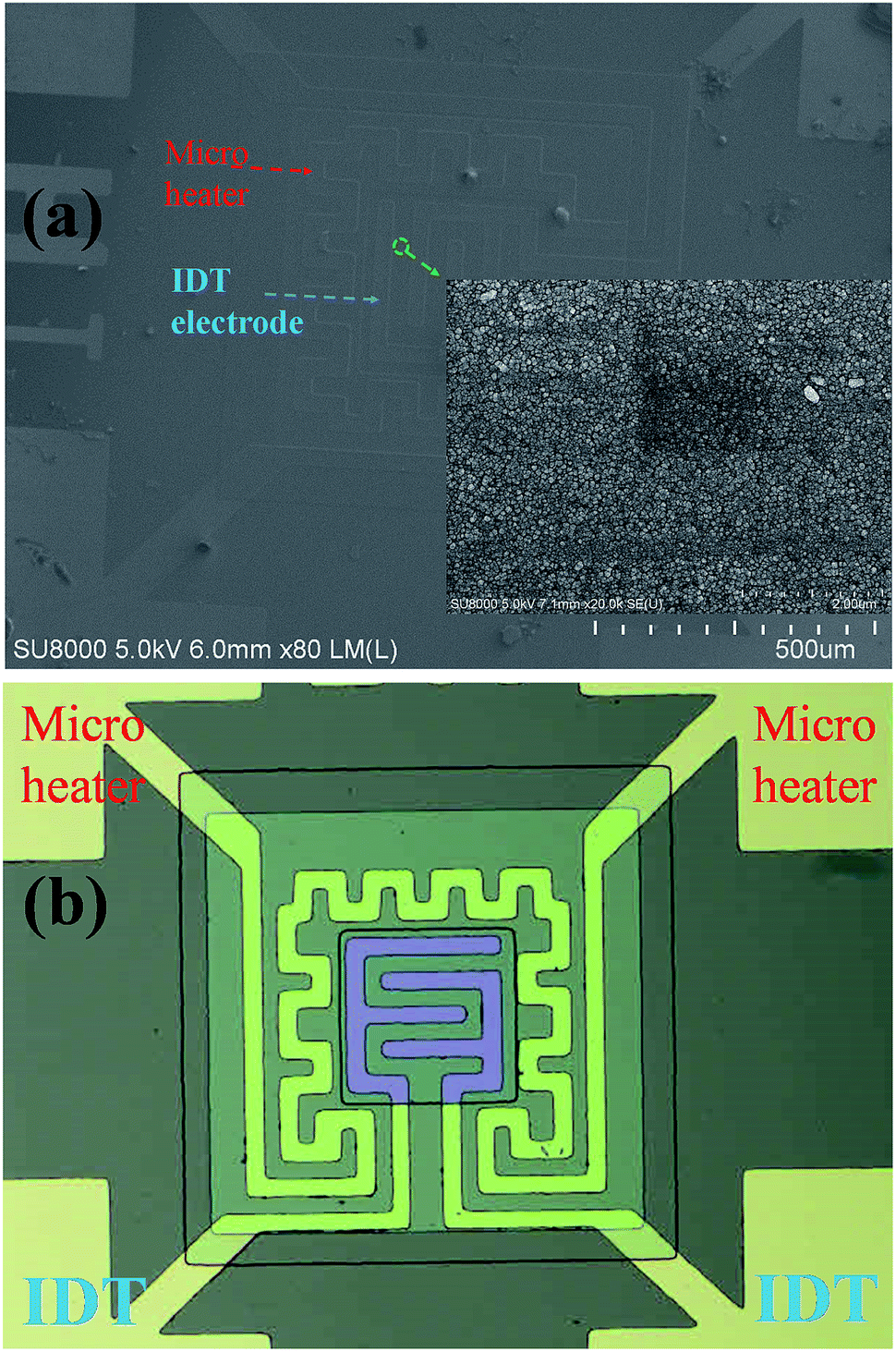 | ||
| Fig. 2 (a) The top view SEM images of the YSZ/SnO2 MEMS SO2 gas sensor. The inset shows an enlarged image of the sensing film (green dotted circle). (b) The top optical microscopy image of the YSZ/SnO2 MEMS SO2 gas sensor. | ||
Fig. 3 shows the crystalline properties of YSZ films from their XRD patterns. YSZ films were deposited on a SnO2/SiO2/Si substrate using the sputtering parameters, without thermal treatment. The (111), (200), (220), and (311) peaks denote the crystallization planes of YSZ (JCPDS 30-1468). The (111) is the main growth plane.
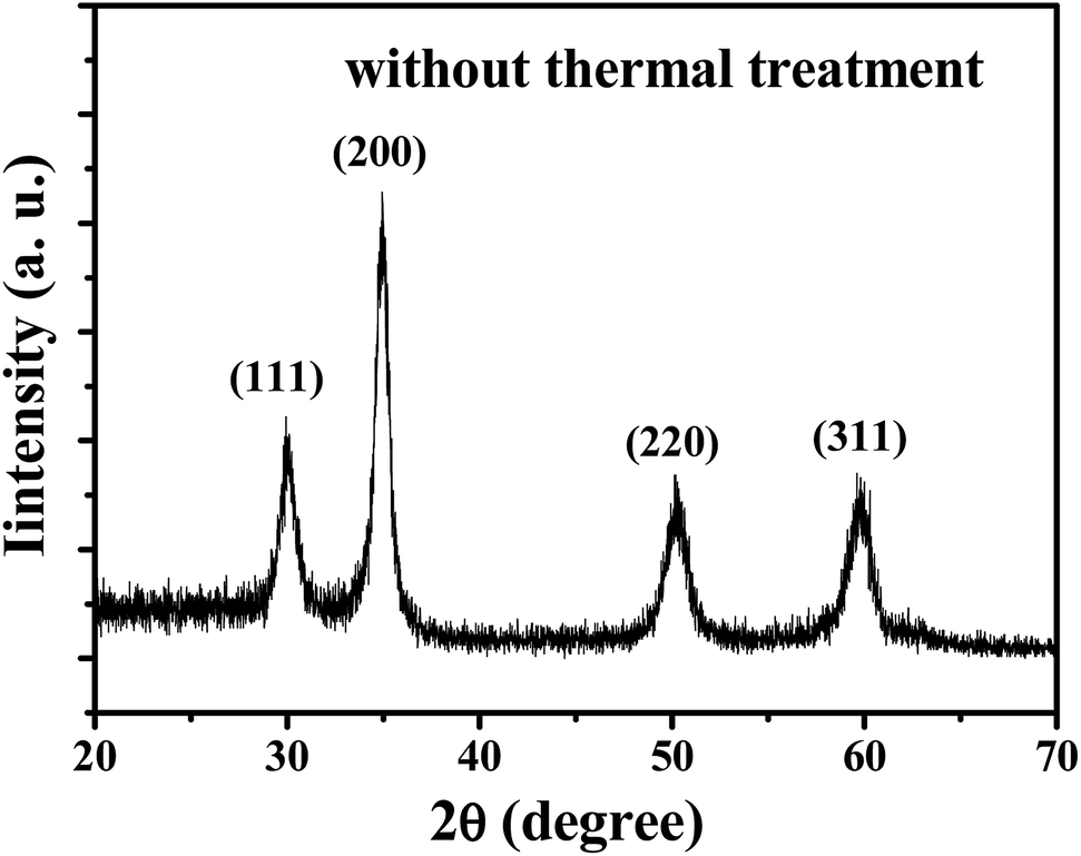 | ||
| Fig. 3 The XRD patterns for YSZ films: YSZ films were deposited on a SnO2/SiO2/Si substrate. | ||
A resistive heater operates on the metal wire thermal principle. Fig. 4(a) shows infrared thermal images of the YSZ/SnO2 gas sensor. There is a temperature difference between the micro heater (red square) and the suspension structure (red dashed lines). The other area is also approximately at room temperature because the micro heater provides a heat source and the suspension structure prevents thermal diffusion. The temperature of the sensing film is approximately 201 °C, 251 °C, 297 °C, 350.6 °C and 400 °C when the current in the micro-heater is approximately 33 mA, 37 mA, 39 mA, 42 mA and 44 mA, respectively, as shown in Fig. 4(b). The current increase linearly as the temperature is increased. When the temperature of the sensing film is 201 °C, 251 °C, 297 °C, 350.6 °C, and 400 °C, the required power is 103 mW, 136 mW, 164 mW, 197 mW, and 229 mW, respectively.
 | ||
| Fig. 4 (a) Infrared thermal images of the YSZ/SnO2 gas sensor and (b) the temperature of the sensing film. | ||
Fig. 5 shows the detector sensor responses for three SO2 gas sensors, measured at 400 °C. During these measurements, 250 ppb SO2 gas was introduced into a sealed chamber and the resistivity of the sensor was measured in air (Ra) and in the presence of SO2 gas (Rb). To quantify the sensor's performance, the response of this sensor is [((Ra − Rb)/Ra) × 100%].11 This definition gives a sensor response of 16% for the YSZ/SnO2 sensing film with the MEMS structure (micro-heater and suspending structure). The sensor response is only around 10% for the pure SnO2 thin film. In other words, the sensitivity to SO2 gas is significantly increased by the deposition of YSZ film on the SnO2 thin film surface. A sample with only the YSZ thin film was prepared and the same SO2 gas sensing measurement at 400 °C was performed. The inset in Fig. 5 shows that the sensor response for the sample with only the YSZ film is a null response. This result shows that the large 16% sensor response is attributable to the SnO2 thin film with YSZ film (YSZ/SnO2). It has been reported that the SnO2 can be used to sense toxic gas with low sensitivity at higher temperatures.10,12 In terms of the sensing mechanism for a YSZ/SnO2/MEMS SO2 sensor, the YSZ thin film allows the redox reaction and the SnO2 thin film acts as an electronic transmission path. As shown in Fig. 6(a), when the YSZ/SnO2/MEMS SO2 sensor is surrounded by air, oxygen molecules are adsorbed onto the YSZ surface and capture electrons from the sensing thin film to generate chemisorbed oxygen species (O2−, O2−, O−). Therefore, the sensor becomes highly resistive. When SO2 gas is introduced, the sensor is exposed to traces of reductive gas. The reductive gas reacts with the oxygen species on the YSZ surface and the concentration of oxygen species on the YSZ surface is reduced, so the concentration of electrons is increased, as shown in Fig. 6(b) and the sensor becomes more conductive.
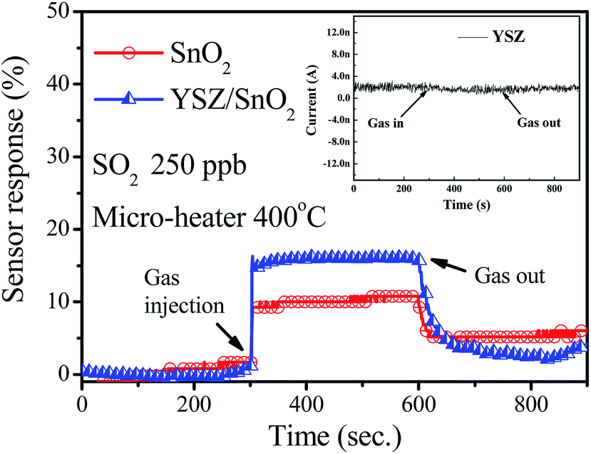 | ||
| Fig. 5 Detector sensor responses for various SO2 gas sensors, measured at 400 °C. The inset in Fig. 4 shows that the sensor response for the sample with only the YSZ film. | ||
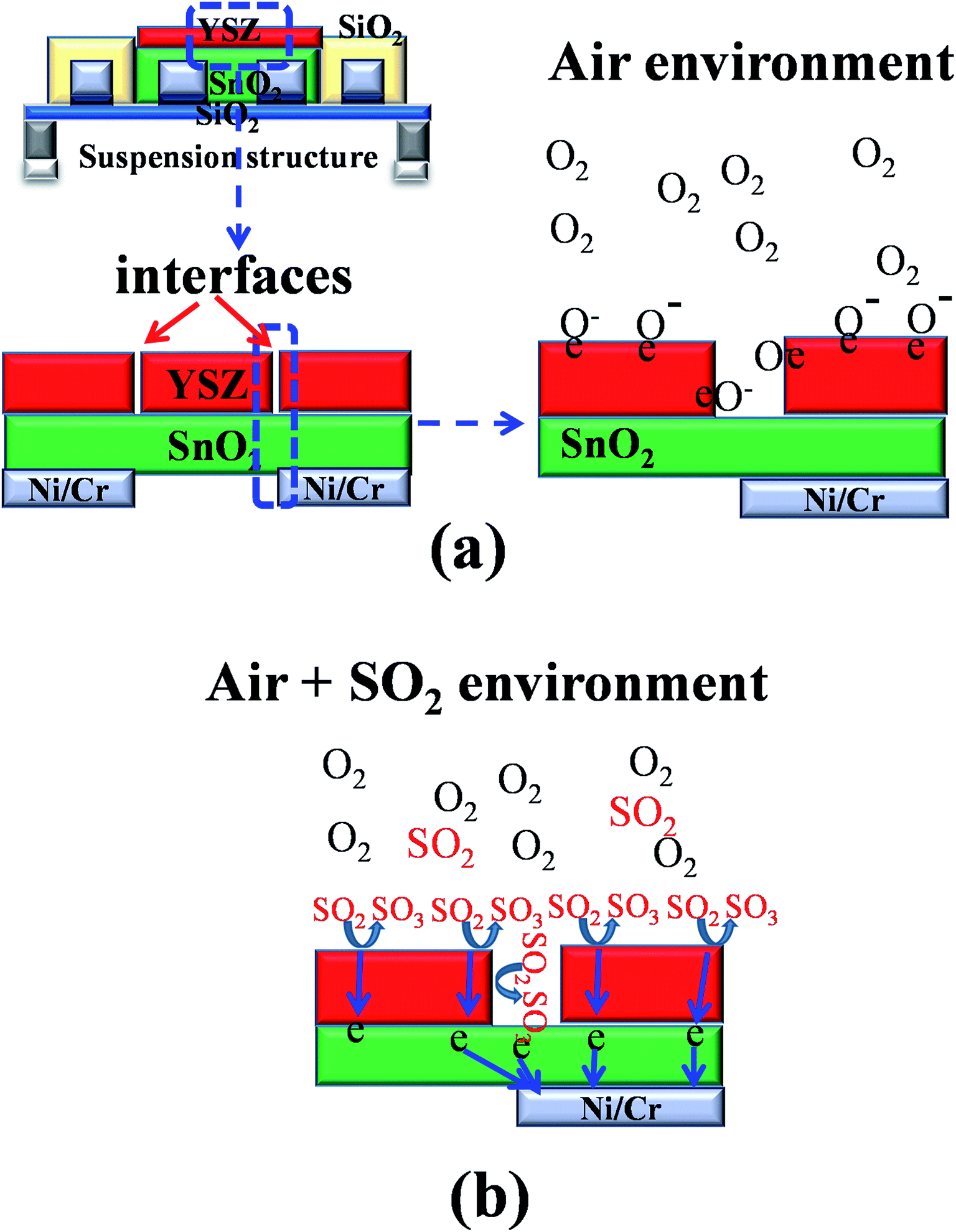 | ||
| Fig. 6 Schematic diagram of a YSZ/SnO2/MEMS SO2 sensor surrounded by (a) air and (b) SO2 gas. | ||
Fig. 7 shows the sensor response of the YSZ/SnO2/MEMS sensor measurement various gases at 400 °C. It was found that the measured response is around 16% and 6% when the concentration of injected SO2 and H2S gas is 250 ppb, respectively. It also was found that the sensor response of YSZ/SnO2/MEMS sensor is not obvious when the concentration of NH3 and NO2 gases are 250 ppb, respectively. The measured results was shown that the YSZ/SnO2/MEMS sensor is more responsive to sulfide; especially SO2 gas.10
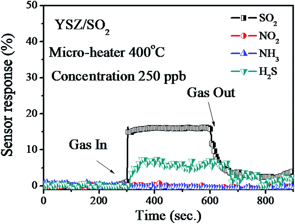 | ||
| Fig. 7 The sensor response for the YSZ/SnO2/MEMS sensor to various gases at 400 °C. | ||
Fig. 8 shows the variation in sensor response variations for a YSZ/SnO2/MEMS SO2 sensor when it is exposed to pumped SO2 gas. These measurements were performed by injecting various amounts of SO2 gas into the sealed chamber, followed by pumping at 400 °C (micro-heater). Using the same definition, the measured response is around 16%, 23%, 27% and 31% when the concentration of injected SO2 gas is 250 ppb, 500 ppb, 750 ppb and 1000 ppb, respectively. In other words, the sensor response increases when the SO2 gas concentration increases. The measured device resistivity also responds rapidly when SO2 is injected gas into the chamber and pumped away. This result shows that the fabricated sensor responds rapidly.
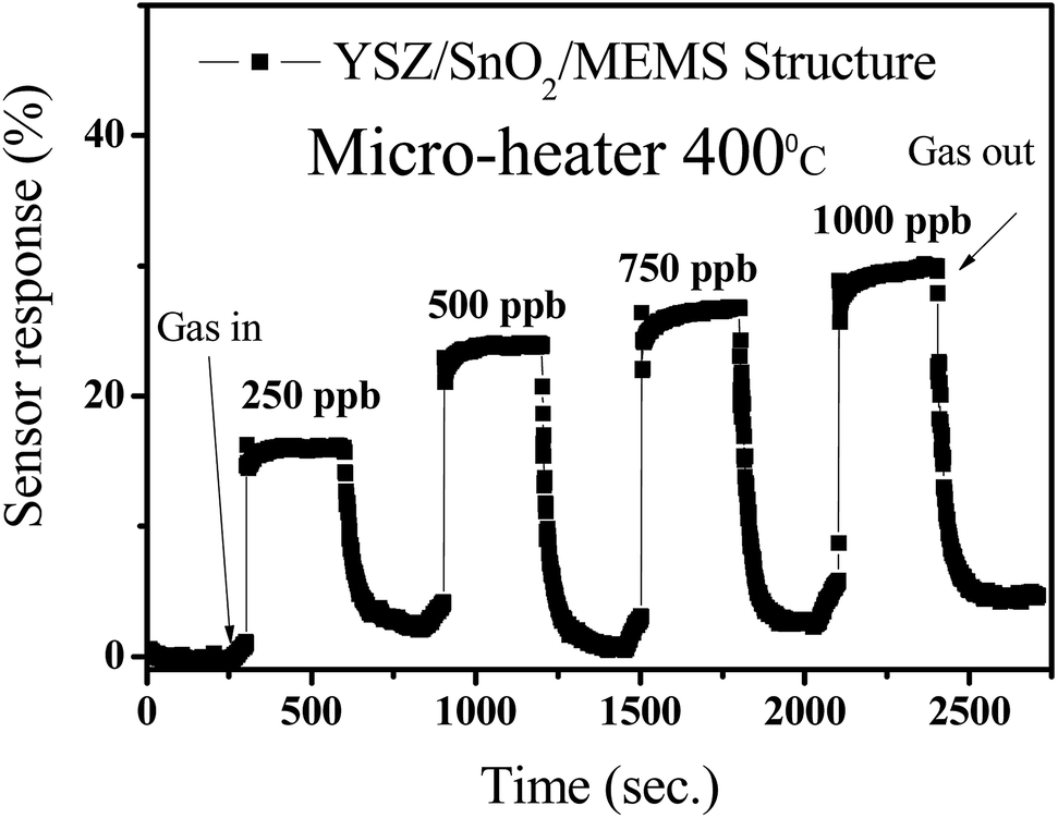 | ||
| Fig. 8 The variation in sensor response for the YSZ/SnO2/MEMS sensor material when SO2 gas is injected and pumped. | ||
Fig. 9(a) shows the sensor response for the YSZ/SnO2 sensor at various temperatures. It should be noted that only 250 ppb SO2 gas was injected into the chamber for these measurements. The measured responses are around 6%, 45%, 20% and 16% when the sensor is operated at 250 °C, 300 °C, 350 °C and 400 °C, respectively. In other words, sensor response increases initially, reaches a maximum at 300 °C and then begins to decrease as the operational temperature is increased from 250 to 400 °C. At low temperatures, the poor sensor response is attributed to the fact that SO2 molecules do not have enough thermal energy to react with the surface-adsorbed oxygen species. However, the reduction in sensor response above 300 °C is attributed to the difficulty of exothermic SO2 gas adsorption.11 This result is similar to that of the study by Duan et al.13 To verify the reproducibility of the YSZ/SnO2/MEMS SO2 sensors, three good samples were randomly produced using the same wafer, as shown in Fig. 9(b). It is seen that the results are reproducible with an inaccuracy of ±5%. These values show that the sensor that is proposed by this study has many applications.
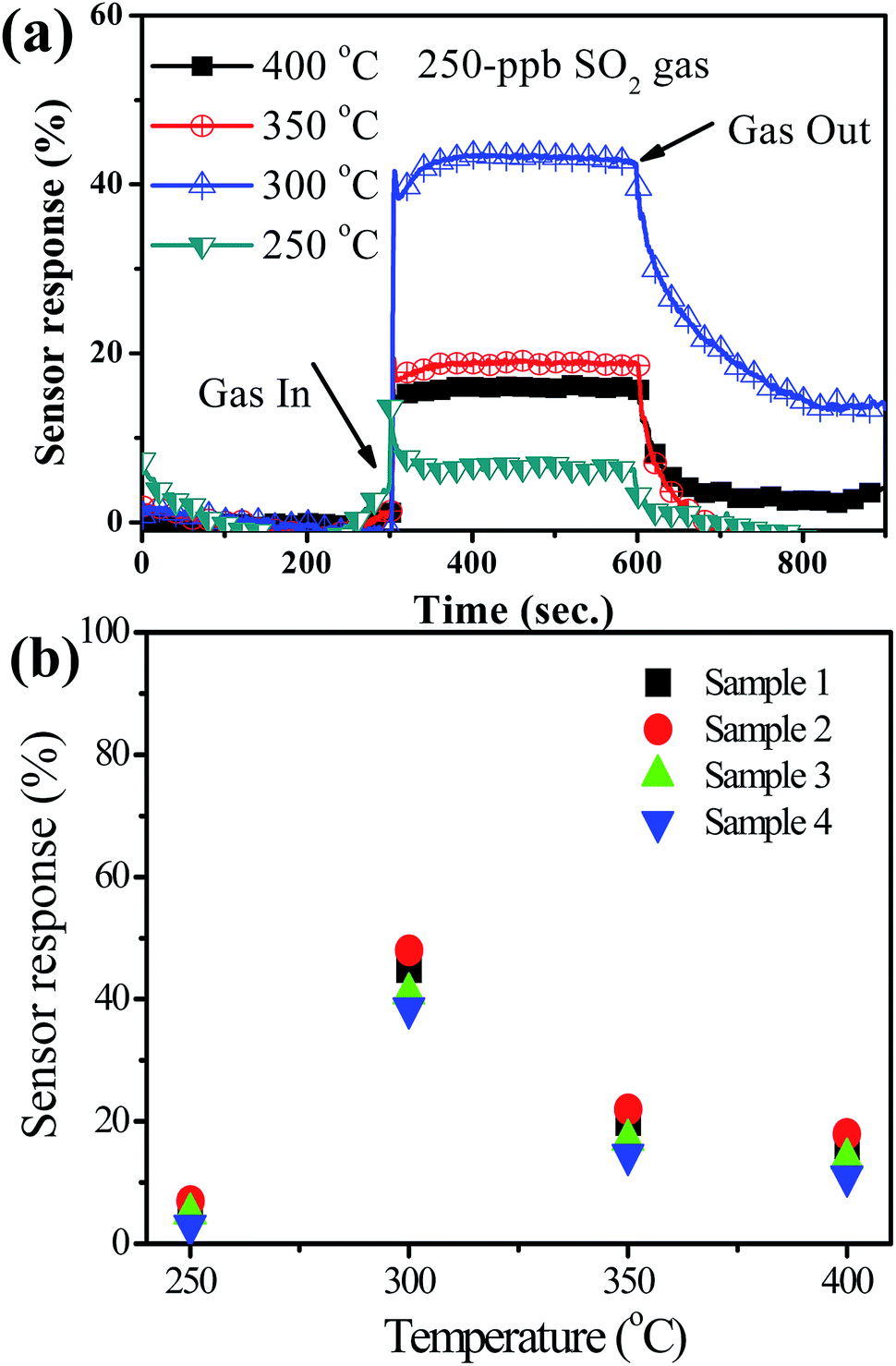 | ||
| Fig. 9 (a) Sensor response for the YSZ/SnO2 sensor at various temperatures and. (b) Five of the same samples at various temperatures (including the sensor of (a)). | ||
Conclusion
In summary, YSZ film is deposited by RF sputtering into a SnO2 MEMS SO2 gas sensor to form a YSZ/SnO2 MEMS SO2 gas sensor. XRD analysis shows the presence of (111), (200), (220), and (311) peaks that denote the crystallization planes of YSZ. Compared with a SnO2 MEMS SO2 gas sensor and a YSZ MEMS SO2 gas sensor, a YSZ/SnO2 MEMS SO2 gas sensor has the best sensor response when the sensors are at 400 °C and in 250 ppb SO2 gas ambience. The measured responses for the YSZ/SnO2 sensor are also around 6%, 45%, 20% and 16% when the sensor is operated at 250 °C, 300 °C, 350 °C and 400 °C, respectively.Conflicts of interest
There are no conflicts to declare.Acknowledgements
The authors would like to thank the Ministry of Science and Technology, Taiwan (NARL-AQI-107-005, 106-2221-E-992-372-MY3, B10708); Center for Intelligent Machines and Smart Materials; Taiwan Semiconductor Research Institute.References
- E. Stokstad, Ammonia pollution from farming may exact hefty health costs, Science, 2014, 343, 238 CrossRef CAS PubMed.
- Y. Zhao, L. Duan, J. Xing, T. Larssen, C. P. Nielsen and J. M. Hao, Soil acidification in China: is controlling SO2 emissions enough, Environ. Sci. Technol., 2009, 43, 8021–8026 CrossRef CAS.
- Y. Liu, X. Xu, Y. Chen, Y. Zhang, X. Gao, P. Xu, X. Li, J. Fang and W. Wen, An integrated micro-chip with Ru/Al2O3/ZnO as sensing material for SO2 detection, Sens. Actuators, B, 2018, 262, 26–342 CrossRef CAS.
- M. L. Yin, Y. Yao, H. B. Fan and S. Z. Liu, WO3-SnO2 nanosheet composites: Hydrothermal synthesis and gas sensing mechanism, J. Alloys Compd., 2018, 736, 322–331 CrossRef CAS.
- C. Schwandta, R. V. Kumara and M. P. Hills, Solid state electrochemical gas sensor for the quantitative determination of carbon dioxide, Sens. Actuators, B, 2018, 265, 27–34 CrossRef.
- F. C. Antunes, C. A. Goulart, M. R. B. Andreeta and D. P. F. de Souza, YSZ/Al2O3 multilayer thick films deposited by spin coating using ceramic suspensions on Al2O3 polycrystalline substrate, Mater. Sci. Eng., B, 2018, 228, 60–66 CrossRef CAS.
- C. L. Lu, S. J. Changa, T. C. Weng and T. J. Hsueh, A Bifacial SnO2 thin film Ethanol Gas Sensor, IEEE Electron Device Lett., 2018, 39, 1223–1225 CAS.
- P. Mitra, A. P. Chatterjee and H. S. Maiti, ZnO thin film sensor, Mater. Lett., 1998, 35, 33–38 CrossRef CAS.
- C. H. Lin, S. J. Chang and T. J. Hsueh, A WO3 Nanoparticles NO Gas Sensor Prepared by Hot-Wire CVD, IEEE Electron Device Lett., 2017, 38, 266–269 CAS.
- C. A. Betty and S. Choudhury, Charge carrier transport in nanocrystalline SnO2 thin film sensor and temperature dependence of toxic gas sensitivity, Sens. Actuators, B, 2016, 237, 787–794 CrossRef CAS.
- S. J. Chang, T. J. Hsueh, I.-C. Chen and B. R. Huang, Highly sensitive ZnO nanowire CO sensors with the adsorption of Au nanoparticles, Nanotechnology, 2008, 19, 175502–175506 CrossRef PubMed.
- A. Cirera, A. Vila, A. Diéguez, A. Cabot, A. Corne and J. R. Morante, Microwave processing for the low cost, mass production of undoped and in situ catalytic doped nanosized SnO2 gas sensor powders, Sens. Actuators, B, 2000, 64, 65–69 CrossRef CAS.
- Z. Duan, Y. Zhang, Y. Tong, H. Zou, J. Peng and X. Zheng, Mixed-Potential-Type Gas Sensors Based on Pt/YSZ Film/LaFeO3 for Detecting NO2, J. Electron. Mater., 2017, 46, 6895–6900 CrossRef CAS.
| This journal is © The Royal Society of Chemistry 2019 |