DOI:
10.1039/C9RA03345A
(Paper)
RSC Adv., 2019,
9, 20424-20431
Facile synthesis of Camellia oleifera shell-derived hard carbon as an anode material for lithium-ion batteries†
Received
5th May 2019
, Accepted 25th June 2019
First published on 1st July 2019
Abstract
A comparatively facile and ecofriendly process has been developed to synthesize porous carbon materials from Camellia oleifera shells. Potassium carbonate solution (K2CO3) impregnation is introduced to modify the functional groups on the surface of Camellia oleifera shells, which may play a role in promoting the development of pore structure during carbonization treatment. Moreover, a small amount of naturally embedded nitrogen and sulfur in the Camellia oleifera shells can also bring about the formation of pores. The Camellia oleifera shell-derived carbon has a large specific surface area of 1479 m2 g−1 with a total pore volume of 0.832 cm3 g−1 after being carbonized at 900 °C for 1 h. Furthermore, when used as an anode for lithium-ion batteries, the sample shows superior electrochemical performance with a specific capacity of 483 mA h g−1 after 100 cycles measured at 200 mA g−1 current density. Surprisingly, the specific capacity is even gradually increased with cycling. In addition, this sample exhibits almost 100% retention capacity after 250 cycles at a current density of 200 mA g−1.
1. Introduction
Accompanied by fossil energy consumption, pollution and the greenhouse effect, energy and environmental problems have become a global concern in modern society.1,2 The current tremendously growing energy demand is forcing the scientific community to focus on developing new technologies that are useful for the exploitation of renewable resources in search of high-performance, cost-effective, safe and environmentally friendly energy conversion and storage systems.3 Electrochemical energy storage devices, such as Li-ion batteries (LIBs) and Na-ion batteries (NIBs), demonstrate great potential and have attracted broad research attention. Currently, LIBs play a dominant role in the battery market and are widely used in portable devices, such as laptop computers and cell phones.4 This type of battery possesses a number of outstanding features, such as high energy density, elevated operating potential, extended cycle life, no memory effect, and environmental friendliness.5,6 However, there are still a number of open challenges that remain to be faced. The availability of global lithium resources is decreasing, and prices are rising. On the other hand, graphite is the most widely used anode for commercial rechargeable LIBs. However, confined by its limited storage capacity (372 mA h g−1) and low rate performance, graphite cannot satisfy the urgent demand for high-performance LIBs.7,8 In consideration of the cost of electrochemical energy storage systems, sodium ion batteries (NIBs), which use sodium as the counter electrode, have attracted great attention. Sodium is cheap, abundant and widely available with respect to its lithium counterpart. However, finding suitable anode materials for sodium ion batteries has plagued many scientists. The ionic radius of Na+ (102 nm) is larger than that of Li+ (76 nm), which leads to poor kinetics in the Na+ (de)insertion reaction, further deteriorating the cycling performance and rate performance of NIBs.9,10 Therefore, in such a scenario, the exploitation of advanced active anode materials with high performance is of particular importance. In addition, ideal electrode materials should be obtained from renewable resources in an efficient manner, taking into account environmental issues and economic value.11,12
In the context of the materials used, biomass-derived hard carbon materials, which are abundant, easily accessible, low cost and renewable,13 have attracted extensive attention in the fabrication of high-performance anodes for LIBs. Moreover, due to the porosity of these biomass carbon materials, they can provide a wide channel for the charge-transfer reaction and facilitate ion transport by shortening diffusion pathways.14 Accordingly, in recent years, porous carbons derived from biomass for LIB anodes have been explored with a wide range of sources, such as olive,15,16 cherry stone,7,15 water hyacinth,17 rice husk,18 coconut oil,19 peanut shell,20 sweet potato,21 cotton,22 litchi,23 ramie fiber and corncob.24 In one study, byproduct rice husk was used as a carbon precursor and applied as an anode for LIBs, presenting a capacity of 403 mA h g−1 after 100 cycles at a current density of 75 mA g−1, higher than that of commercial graphite anodes.18 Similarly, a N-self-doped hierarchically porous carbon from the stem medulla of water hyacinth was synthesized by a facile self-activation approach, exhibiting excellent cycle performance and rate capacity when used as an anode in LIBs.17
Camellia oleifera shells are byproducts of camellia oil and are produced in large amounts in Hunan Province, which is one of the largest cultivation areas of Camellia oleifera in China. Moreover, the Camellia oleifera industry has been established as a “First livelihood project” in Hunan Province to overcome poverty. This means that more Camellia oleifera shells after pressing oil will be produced as waste materials. However, the shells, notably, are not only rich in hemicellulose and cellulose, which are excellent sources of carbon, but also comprise a bit of naturally embedded nitrogen and sulfur. The chemical composition of the raw material is listed in Table 1. To date, studies on the preparation of porous carbon from Camellia oleifera shells have rarely been reported. It has been identified that biomass-derived porous carbons can be activated with activating agents such as KOH,25–28 NaOH29–31 and ZnCl2.32–34 However, the strong basicity and toxic features of such agents make them hazardous for application in practice. Here, we propose a novel synthesis approach for porous carbon from Camellia oleifera shells (COSDHCs) activated by using K2CO3 as an activation agent, which is inexpensive and nontoxic.35 When the as-prepared COSDHCs were used as an anode material for LIBs, they achieved a high specific capacity of 483 mA h g−1 after 100 cycles. Surprisingly, almost 100% retention capacity after 250 cycles at a current density of 200 mA g−1 was measured. The excellent electrochemical performance of the as-prepared COSDHCs can be ascribed to their large specific surface area of 1479 m2 g−1 and high pore volume of 0.832 cm3 g−1 after activation by K2CO3, which benefits the volume expansion of the COSDHCs in the lithiation and delithiation processes during charge and discharge cycling. Furthermore, the porous architecture can promote electrolyte diffusion within a local environment, which can enhance the Li-ion kinetics for reaction with COSDHCs, as verified by CV and impedance measurements.
Table 1 Chemical compositions of the raw material and carbon
| Sample |
Elemental analysis (wt%) |
| C |
N |
S |
H |
| Raw material |
44.32 |
0.35 |
0.19 |
5.62 |
| COSDHC900-1 |
72.59 |
0.45 |
0.17 |
2.26 |
2. Experimental section
2.1. Material synthesis
Camellia oleifera shells obtained from an oil mill in Hunan were first washed with ethanol and then dried at 80 °C overnight, followed by grinding into a fine powder by mechanical milling. Then, 2 g potassium carbonate (K2CO3) was dissolved in 8 mL deionized water to prepare a clear solution. A total of 1.5 g of the Camellia oleifera shell powder was immersed into the solution, stirred overnight and dried at 120 °C for 6 h in an air drying oven. Finally, the obtained samples were milled and prepared by pyrolysis in a tubular furnace at a heating rate of 5 °C min−1 under Ar atmosphere. The samples are denoted as COSDHC-T-H, where T and H represent the pyrolysis temperature and carbonization time, respectively; samples were carbonized at 800 and 900 °C for 1 and/or 2 h to yield COSDHC800-1, COSDHC800-2 and COSDHC900-1. After carbonization, the samples were boiled for 20 min in 20 wt% HCl to remove any residual impurities, sequentially washed with hot water several times until the solution was neutral and dried at 80 °C overnight in a vacuum oven.
2.2. Material characterization
The raw material and as-prepared samples were subjected to various forms of characterization. The distribution of the major elements in the raw material and carbonized product was determined by elemental analysis (VARIO ELIII, Germany) and X-ray photoelectron spectroscopy (XPS, SCALAB 250Xi, Thermo Fisher Scientific, America). Thermogravimetric analysis of the impregnated sample was carried out with a Netzsch STA 409PC thermal analyzer at a heating rate of 5 °C min−1 from room temperature to 1000 °C under N2 atmosphere. The morphology of the synthesized carbon materials was observed using scanning electron microscopy (SEM, Hitachi, S-4800), transmission electron microscopy (TEM, FEI Tecnai G20) operating at 200 kV and high-resolution transmission electron microscopy (HRTEM). X-ray diffraction patterns (XRD, Bruker D8 Advance), Raman spectroscopy (Renishaw Invia-reflex, 532 nm laser) and Fourier transform infrared spectroscopy (FT-IR, IR Affinity) were used to examine the degree of graphitization, crystallinity, and functional groups. The surface area was characterized by nitrogen adsorption at 200 °C with a Quantachrome NOVA1000e apparatus, and the pore size distributions were analyzed via the Barrett–Joyner–Halenda (BJH) method.
2.3. Electrochemical measurements
The electrode slurry was formulated from a mixture of 80 wt% as-prepared powder, 10 wt% super carbon black, and 10 wt% polymer binder (polyvinylidene fluoride (PVDF)) using N-methyl pyrrolidinone (NMP) as the dissolving solvent. Then, the carbon-coated COSDHC electrodes were mechanically pressed and assembled into CR2032 coin cells with lithium foil as the counter and reference electrodes. The LIB electrolyte and separator were 1 M LiPF6 in a mixture of ethylene carbonate and diethyl carbonate at a volume ratio of 1![[thin space (1/6-em)]](https://www.rsc.org/images/entities/char_2009.gif) :1 and a polyethene separator (Celgard 2400), respectively. All test cells were assembled in an Ar-filled glovebox with sub-0.1 ppm water and oxygen contents. The galvanostatic charge/discharge measurements were performed on a Land CT2001A system (Wuhan, China) with a cutoff voltage window of 0.01–3 V (vs. Li/Li+) at 25 °C. The cyclic voltammetry (CV) curves were obtained on an Autolab PGSTAT302N (Metrohm-Autolab BV, Utrecht, The Netherlands) electrochemical workstation with a sweep rate of 0.1 mV s−1. Electrochemical impedance spectroscopy (EIS) was measured in the frequency range from 100 kHz to 0.01 Hz at 5 mV s−1.
:1 and a polyethene separator (Celgard 2400), respectively. All test cells were assembled in an Ar-filled glovebox with sub-0.1 ppm water and oxygen contents. The galvanostatic charge/discharge measurements were performed on a Land CT2001A system (Wuhan, China) with a cutoff voltage window of 0.01–3 V (vs. Li/Li+) at 25 °C. The cyclic voltammetry (CV) curves were obtained on an Autolab PGSTAT302N (Metrohm-Autolab BV, Utrecht, The Netherlands) electrochemical workstation with a sweep rate of 0.1 mV s−1. Electrochemical impedance spectroscopy (EIS) was measured in the frequency range from 100 kHz to 0.01 Hz at 5 mV s−1.
3. Results and discussion
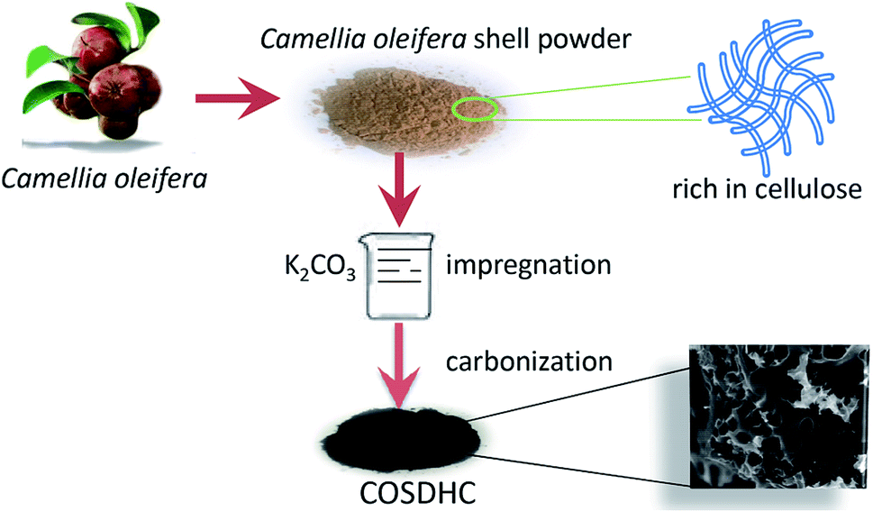
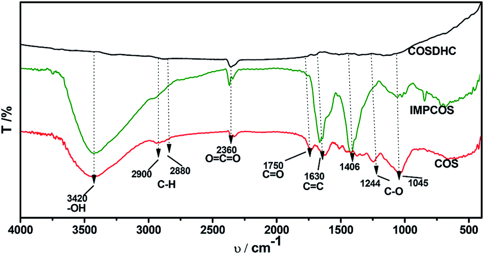
The COSDHCs were prepared by impregnation and carbonization, and the synthetic route of this method is shown in Fig. 1. The pyrolysis process of the precursor (the impregnated Camellia oleifera shell powder) was examined by thermal analyzer. The TG curve is shown in Fig. S1.† A significant weight loss of 29 wt% was caused by the evaporation of residual water and the decomposition of hemicellulose, cellulose and even lignin stored in the Camellia oleifera shell.36 Another 55.2 wt% mass loss may be due to decomposition and reduction reactions of K2CO3.37 Then, infrared spectroscopy was used to determine the changes in functional groups. Fig. 2 displays the spectra of the raw material, the sample impregnated with K2CO3 and its char annealed at 900 °C. The impregnated Camellia oleifera shell powder (IMPCOS) was carbonized under an Ar atmosphere at a rate of 5 °C min−1 from room temperature to 900 °C and held for 1 h (COSDHC900-1).38 When comparing the three spectra, it can be seen that, in addition to the carbon spectrum, the spectra show a strong broad absorption band at ∼3420 cm−1, which is assigned to the stretching vibration of phenolic hydroxyl or alcoholic hydroxyl groups.39 The absorption peaks at 2900 and 2880 cm−1 can be attributed to the C–H stretching vibration of lignin polysaccharides. The C–H stretching vibration is weakened in the high-temperature (900 °C) carbonized materials, which may be due to the decomposition of lignin polysaccharides in the Camellia oleifera shells, such as cellulose and hemicelluloses.40 The peaks at 2360 cm−1 and 1750 cm−1 are ascribed to O![[double bond, length as m-dash]](https://www.rsc.org/images/entities/char_e001.gif) CO vibrations and the CO bond stretching vibration of oxygen-containing functional groups, such as carboxyl groups, carbonyl groups and ester groups.38,41 After infiltrating K2CO3, the peaks corresponding to oxygen-containing functional groups are weakened, because of the effect of K2CO3 during the impregnation process.35 The CO band almost disappeared in the infrared spectrum of the biomass carbon produced at 900 °C, confirming that CO bonds are more likely to be broken, resulting in the formation of CO and CO2. A strong band is observed at approximately 1630 cm−1, which may be generated by the aromatic skeleton region of the Camellia oleifera shell powder or CC stretching vibration, indicating that the biomass carbon gradually forms an aromatic structure.42 When the temperature is higher than 700 °C, carbon in the coke is removed as CO gas by K2CO3 reduction.35,37 The band is greatly attenuated for the carbonized product. The peaks located at 1400–1000 cm−1 are attributed to C–O stretching in alcohols, phenols, ethers and esters. These broad bands are unique to the COS and impregnated samples; nevertheless, the bands almost vanish for COSDHC900-1. This clearly indicates that the C–O bonds in acids, alcohols, phenols, ethers and esters disappear during the carbonization process.43 Overall, the CC and C–O intensities of Camellia oleifera shells dipped in K2CO3 solution are significantly higher than those of the corresponding raw materials and activated carbon samples. This contributes to the degree of aromatization of biomass carbon and tendency to form graphite crystallites. In addition, the amounts of functional groups are greatly reduced, which is also conducive to porosity.
CO vibrations and the CO bond stretching vibration of oxygen-containing functional groups, such as carboxyl groups, carbonyl groups and ester groups.38,41 After infiltrating K2CO3, the peaks corresponding to oxygen-containing functional groups are weakened, because of the effect of K2CO3 during the impregnation process.35 The CO band almost disappeared in the infrared spectrum of the biomass carbon produced at 900 °C, confirming that CO bonds are more likely to be broken, resulting in the formation of CO and CO2. A strong band is observed at approximately 1630 cm−1, which may be generated by the aromatic skeleton region of the Camellia oleifera shell powder or CC stretching vibration, indicating that the biomass carbon gradually forms an aromatic structure.42 When the temperature is higher than 700 °C, carbon in the coke is removed as CO gas by K2CO3 reduction.35,37 The band is greatly attenuated for the carbonized product. The peaks located at 1400–1000 cm−1 are attributed to C–O stretching in alcohols, phenols, ethers and esters. These broad bands are unique to the COS and impregnated samples; nevertheless, the bands almost vanish for COSDHC900-1. This clearly indicates that the C–O bonds in acids, alcohols, phenols, ethers and esters disappear during the carbonization process.43 Overall, the CC and C–O intensities of Camellia oleifera shells dipped in K2CO3 solution are significantly higher than those of the corresponding raw materials and activated carbon samples. This contributes to the degree of aromatization of biomass carbon and tendency to form graphite crystallites. In addition, the amounts of functional groups are greatly reduced, which is also conducive to porosity.
 |
| | Fig. 1 The synthesis of porous hard carbons from Camellia oleifera shell. | |
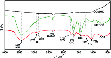 |
| | Fig. 2 FT-IR spectra of the raw material, impregnated sample and carbonized product. | |
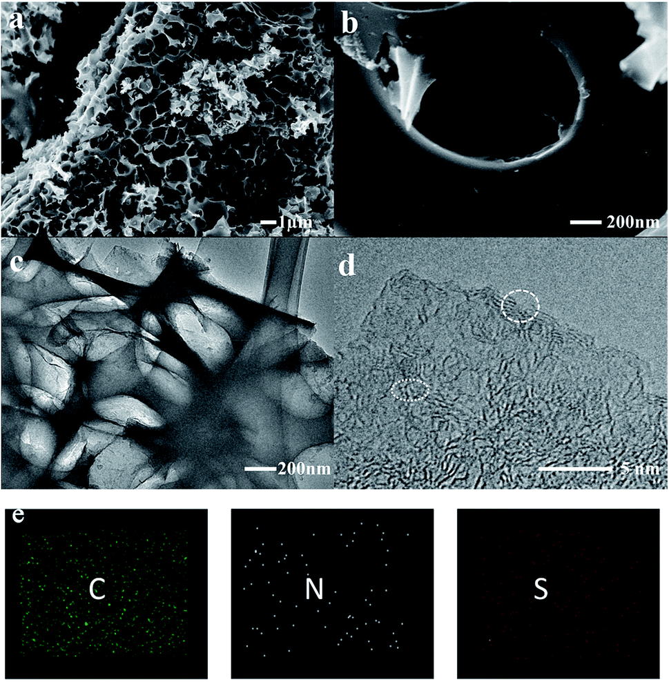
The impregnated samples carbonized at 800 °C for 1 and 2 h and 900 °C for 1 h were characterized and compared. As shown in the scanning electron microscopy (SEM) images, a large amount of cracked macropores and mesopores were generated in the samples carbonized at 800 °C (Fig. S2†). In comparison, the pores of COSDHC900-1 are more evenly distributed, and the surface presents a well-developed cross-linked mesoporous structure with thin walls. These pores can remarkably enhance the active sites for Li-ion storage. Moreover, the interconnected structure formed by the thin walls can act as an ion-buffering reservoir. Furthermore, such a cross-linked mesoporous structure immersed in electrolyte will provide short Li-ion transport and accelerate electrolyte diffusion (Fig. 3a and b).44 These highly developed pores are due to the release of CO during the reduction of K2CO3 in the pyrolysis process.35,41 The typical transmission electron microscopy (TEM) image is shown in Fig. 3c. It is obvious that hierarchical micro- and mesopores are distributed in COSDHC900-1, which can serve as Li-ion containers to increase ion storage.45 In the high-resolution TEM image (Fig. 3d), COSDHC900-1 has an amorphous structure with some small domains of graphite microcrystallites in a short range. The elemental mapping images in Fig. 3e show that Camellia oleifera shells are indeed carbon-rich precursors and contain a small amount of nitrogen and sulfur. X-ray photoelectron spectroscopy (XPS) of the raw material and the sample calcined at 900 °C was further conducted to detect the surface element features (see Fig. S3†). Three peaks, centered at approximately 168 eV, 285 eV and 400 eV, correspond to S 2p, C 1s and N 1s, respectively.46 The N and S contents of COS and COSDHC are quite low with a sparse distribution. Very small amounts of nitrogen and sulfur atoms can also create defects in carbon materials because of their larger radius than C atoms and generate active sites for Li storage.47,48 These results are consistent with those of the element analysis (Table 1).
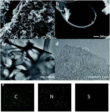 |
| | Fig. 3 Characterization of the COSDHC900-1: (a and b) SEM images, (c) TEM image, (d) high-resolution TEM image, (e) element mapping of C, N, and S. | |
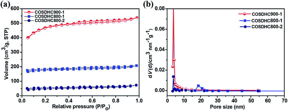
To further investigate the porosity in detail, the three samples were measured by nitrogen adsorption–desorption isotherms (Fig. 4a), and the corresponding pore size distribution curves are shown in Fig. 4b. The isotherms are revealed to be type I, according to IUPAC classification. There exist slight H4 hysteresis loops.49 These loops indicate a series of hierarchical pores, including micropores, mesopores, and a small amount of large pores, in the samples. The surface areas of COSDHC900-1, COSDHC800-1, and COSDHC800-2, calculated by the Brunauer–Emmett–Teller (BET) method, are approximately 1479 m2 g−1, 545 m2 g−1 and 152 m2 g−1, respectively. The detailed results of the Barrett–Joyner–Halenda (BJH) pore size distribution are summarized in Table 2. Among the three as-obtained samples, COSDHC900-1 has the highest specific area and pore volume, benefiting from the combination of micro- and mesopores at the relatively high pyrolysis temperature. Micropores contribute greatly to the surface exposure, while the mesopores mainly contribute to the total pore volume. For COSDHC900-1, the pore volume and average pore diameter are 0.832 cm3 g−1 and 2.25 nm, respectively. These slit-shaped (or cylindrical) and narrow-mouthed pores were primarily produced by CO and K release when the activation temperature reached the melting point of K2CO3 at 891 °C.37 During the carbonization and activation process, K2CO3 is reduced by the non-graphitic carbon50 under inert gas flow, resulting in micropores, and then the existing micropores are enlarged in the carbonization process at that temperature. This leads to the combination of mesopores and micropores within the carbon framework. This unique porous structure with remarkable surface area and large pore volume can provide more adsorption sites for Li ions and electrolyte infiltration to achieve fast ion transport and short diffusion.
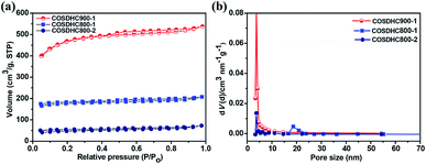 |
| | Fig. 4 (a) Nitrogen-sorption isotherms and (b) pore size distributions obtained for COSDHC900-1, COSDHC800-1 and COSDHC800-2. | |
Table 2 Interlayer distance, specific surface area and pore structure of COSDHC-T-H
| Sample |
2θC002 (o) |
d002 (nm) |
SBET (m2 g−1) |
Vt (cm3 g−1) |
Fraction, % (mesopore) |
| COSDHC800-1 |
20.1 |
0.4414 |
545 |
0.321 |
85.7 |
| COSDHC800-2 |
20.96 |
0.4235 |
152 |
0.113 |
71.7 |
| COSDHC900-1 |
20.14 |
0.4405 |
1479 |
0.832 |
87.3 |
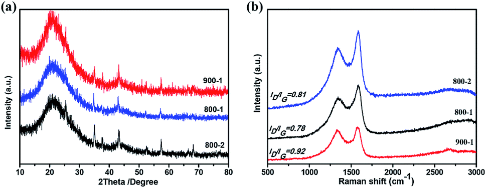
The crystal structure of the samples at different temperatures and carbonization periods was characterized by X-ray diffraction (XRD). As shown in Fig. 5a, two main broad diffraction peaks at 20° and 44° appear in all samples, corresponding to the (002) and (100) lattice planes of amorphous carbon, which is beneficial for Li+ intercalation and deintercalation.17,45 The interlayer spacings of the three samples are summarized in Table 2. Moreover, COSDHC900-1 has sharper peaks than the other samples, suggesting increased crystallinity induced by the high temperature and carbonization period. This is also confirmed by the Raman spectra. Two prominent peaks located at ∼1360 cm−1 and 1590 cm−1 can be seen in Fig. 5b, corresponding to the D and G bands of stacked graphene, respectively. The D band represents the vibrational modes of disordered sp3 carbon caused by edges, defects, and disordered carbon sites, while the G band is related to the E2g vibration of sp2 C atoms in graphene. The intensity ratio of the D band and G band (ID/IG) can be used to reflect the degree of graphitization in carbon materials. The ID/IG ratio of COSDHC900-1 is 0.92, significantly higher than that of COSDHC800-1 (ID/IG = 0.78) and COSDHC800-2 (ID/IG = 0.81), suggesting that more defects are present in the former sample, contributing to the reversible capacity of the anode and improving the Li storage ability.51
 |
| | Fig. 5 (a) XRD patterns and (b) Raman spectra of COSDHC at different temperatures and carbonization periods. | |
The cyclic voltammogram (CV) profiles of COSDHC900-1 recorded in the first three cycles with a scanning rate of 0.1 mV s−1 are shown in Fig. 6a. In the first cycle, the irreversible peak appears at ∼0.5 V, corresponding to the formation of the solid electrolyte interface (SEI) layer on the surface of the electrode,52 which is assigned to the reaction between Li ions and the functional groups on the surface of COSDHC900-1. In subsequent cycles, the CV curves almost keep overlap, which indicates good reversibility with excellent capacity retention and electrochemical stability when Li is intercalated/delaminated.17 Fig. 6b–d show the 1st, 2nd, 50th, and 100th charge/discharge profiles of COSDHC900-1, COSDHC800-1 and COSDHC800-2 electrodes, respectively, for LIBs at a current density of 200 mA g−1 with a voltage range of 3.0–0.01 V. The initial discharge capacities are 629.9, 429.9 and 294 mA h g−1, respectively. A remarkable difference exists in the specific capacity of carbon materials prepared at different temperatures and durations. After 50 cycles, the COSDHC900-1 sample retains a capacity of 473 mA h g−1, but the other electrodes exhibit lower capacities of approximately 250 mA h g−1 and 160 mA h g−1. The specific capacity of COSDHC900-1 shows a gradual increase with increased cycles, indicating that the initially unexposed meso- and micropores become more accessible after long-term repeated cycling.53 Surprisingly, as shown in Fig. 6e, the COSDHC900-1 electrode delivers ultralong cycle stability when cycled at a current density of 0.2 A g−1 and has a higher capacity of 503 mA h g−1, even after 250 cycles, with a coulombic efficiency of almost 100%. Conversely, the other electrodes have lower capacities, mainly because of the low surface area and small number of active sites for the adsorption of Li ions due to low microporosity and mesoporosity. Fig. 6f shows the rate capacity of the COSDHC900-1 sample with 10 cycles at each rate (ranging from 0.1 to 1 A g−1), and the rate capacities of the COSDHC800-1 and COSDHC800-2 samples are shown in Fig. S4.† The reversible capacity of the COSDHC900-1 sample is 581, 415, 281, 211, and 195 mA h g−1 at 0.1, 0.2, 0.4, 0.8, and 1 A g−1, respectively. After the initial 10 cycles, the cell maintains good capacity retention during cycling at different current rates. However, after a high-current-density cycle, the COSDHC900-1 sample returns to a small current of 0.1 A g−1, and the capacity decreases to some extent (424 mA h g−1), which may be caused by the typical characteristics of biomass-derived hard carbon structures.
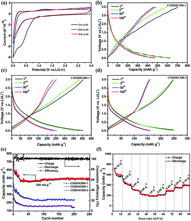 |
| | Fig. 6 (a) CV curves of COSDHC900-1; (b–d) discharge–charge profiles of COSDHC-T-H electrodes; (e) cycling performance of COSDHC-T-H electrodes with a current density of 200 mA g−1 and cycling between 0.01 and 3.0 V vs. Li+/Li; (f) rate performance of COSDHC900-1. | |
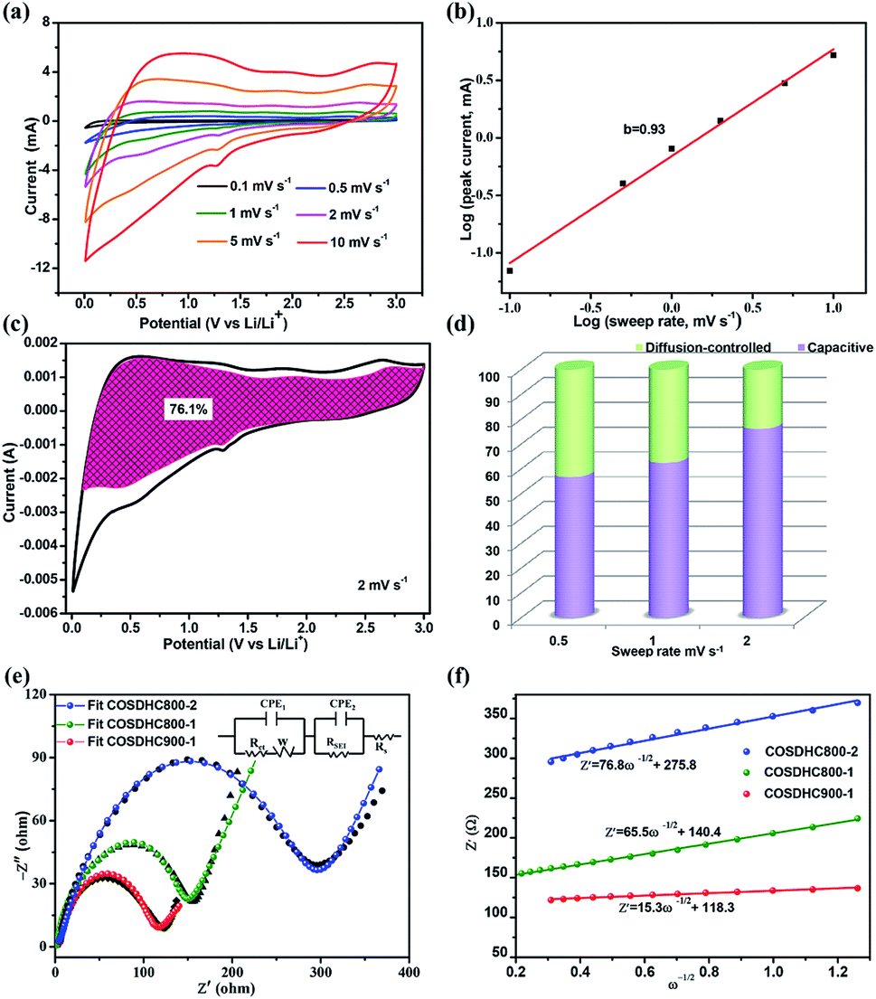
To further investigate the capacitive effect of the as-prepared COSDHC900-1 sample, we examined the electrochemical kinetics of the sample electrode for lithium storage by a series of CV measurements. Fig. 7a shows the stepwise CV curves of the COSDHC900-1 electrode under scan rates ranging from 0.1 to 10 mV s−1. The CV curves retain analogous shapes, and the peaks reflect pseudocapacitive behavior. In general, in CV curves, the peak current (i) against scan rate (ν) is dominated by the equation i = aνb, and the b value can vary from 0.5 to 1 depending on the solvated ion storage mechanism. A b value of 0.5 implies a diffusion-controlled process, while a value of 1.0 indicates that capacitive behavior dominates the charge storage process.10,45,54 In Fig. 7b, the linear relationship between the logarithmic sweep rate and logarithmic peak current is plotted, and the calculated b value for anodic peak is 0.93, suggesting fast kinetics due to a capacitive effect. Furthermore, the quantitative capacitive contribution at the given scan rate can be obtained from another equation: i = k1ν + k2ν1/2, where k1 and k2 represent surface pseudocapacitive-controlled and diffusion-controlled processes, respectively. As a consequence, the capacitive contribution of the COSDHC900-1 anode is approximately 76.1% of the total capacity at 2 mV s−1 (as shown in Fig. 7c). Fig. 7d shows that the pseudocapacitive contribution percentage increases with increasing scan rate. The contributions are 56.7%, 62.4% and 76.1% at scan rates of 0.5 mV s−1, 1 mV s−1 and 2 mV s−1, respectively. Electrochemical impedance spectra (EIS) measurements were conducted to investigate the resistance at the electrode interface, as shown in Fig. 7e. The impedance spectra consist of two main zones: a depressed semicircle at high frequency and a sloping straight line in the low-frequency region. The kinetic parameters were obtained from the equivalent circuit (inset of Fig. 7e), where Rs represents the SEI film resistance, Rct reflects the charge-transfer resistance at the interface, and Zw is ascribed to the Warburg impedance. Moreover, the charge-transfer resistance data are listed in Table 3. The smallest semicircle is observed for the COSDHC900-1 electrode, which suggests that the charge transfer rate at the electrode–electrolyte interface is fast and that the overall process achieves the best reaction kinetics. In the low-frequency region, the relationship between Z′ and ω−0.5 (Fig. 7f) can be used to calculate the Li-ion diffusion coefficient55–57 according to the following equation:
where
A,
n,
F,
C,
R, and
T stand for the electrode area (1.44 cm
2), reactive electron number per chemical formula, Faraday's constant (96
500 C mol
−1), molar concentration of Li ions (1.0 × 10
−3 mol cm
−3), gas constant (8.314 J mol
−1 K
−1), and testing temperature (298 K), respectively.
σw is the Warburg factor. The Warburg factor,
σw, can be derived from the following equation:
| Z′ = Rs + Rf + Rct + σwω−0.5 |
where
ω stands for the angular frequency. The fitted line slopes indicate
σw values of 15.3, 65.5, and 76.8 cm
2 s
−1/2 for COSDHC900-1, COSDHC800-1 and COSDHC800-2, respectively. Thus, the Li-ion diffusion coefficients of COSDHC900-1, COSDHC800-1 and COSDHC800-2 were calculated to be
ca. 0.56 × 10
−12, 0.22 × 10
−13, and 0.3 × 10
−13 cm
2 s
−1, respectively. The lower charge transfer resistance and higher
DLi+ of COSDHC900-1 guarantee excellent performance. It is clear that the structure of COSDHC900-1 enables a short ion-transport pathway with less resistance, leading to a higher rate capacity than that of the other two samples. These results are also consistent with the findings of long-term cycling performance.
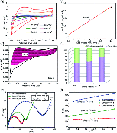 |
| | Fig. 7 (a) CV curves of COSDHC900-1 at different scan rates of 0.1, 0.5, 1, 2, 5 and 10 mV s−1, (b) b-values determined by the plot of log (i) vs. log (ν), (c) capacitive contributions at a scan rate of 2 mV s−1, (d) capacitive contribution ratios at various rates, (e) Nyquist plots and equivalent circuits to simulate EIS results of COSDHC-T-H, (f) the relationship between Z′ and ω−1/2 in the low-frequency region. | |
Table 3 Charge transfer resistances and ion diffusion coefficients from the EIS test
| Sample |
Rct (Ω) |
DLi+ (cm2 s−1) |
| COSDHC800-1 |
136 |
0.22 × 10⁻¹³ |
| COSDHC800-2 |
280 |
0.3 × 10⁻¹³ |
| COSDHC900-1 |
103 |
0.56 × 10⁻¹² |
4. Conclusion
In summary, a porous carbon material has been successfully synthesized from Camellia oleifera shells via K2CO3 impregnation and pyrolysis. After investigating the carbonization temperature and duration, it was found that the carbon sample pyrolyzed at 900 °C for 1 h demonstrates well-developed cross-linked mesoporous structures. This sample exhibits advanced electrochemical performance as an anode for LIBs and a continuous increase in specific capacity (as high as 503 mA h g−1, even after 250 cycles at a current density of 0.2 A g−1). To the best of our knowledge, this is the first report to use such biomass to prepare hard carbon materials as anode materials for Li-ion batteries. Moreover, the demonstrated comparatively facile synthesis process will make these electrodes both inexpensive and environmentally friendly. It is believed that these findings will benefit the electrochemical community from both economic and knowledge perspectives.
Conflicts of interest
There are no conflicts to declare.
Acknowledgements
This research was supported by the China Scholarship Council, Natural Science Foundation of Hunan (No. 2017JJ2040), the Australia Research Council and the University of Technology Sydney (UTS) through the Discovery Early Career Researcher Award (DECRA DE170101009), ARC Discovery Project (DP170100436), UTS Chancellor's Postdoctoral Research Fellowship project (PRO16-1893), and UTS Early Career Researcher Grants ECRGS PRO16-1304.
Notes and references
- Y. Sun, Q. Wu and G. Shi, Energy Environ. Sci., 2011, 4, 1113–1132 RSC.
- F. Zhang, T. Zhang, X. Yang, L. Zhang, K. Leng, Y. Huang and Y. Chen, Energy Environ. Sci., 2013, 6, 1623–1632 RSC.
- F. Bella, A. B. Muñoz-García, F. Colò, G. Meligrana, A. Lamberti, M. Destro, M. Pavone and C. Gerbaldi, ACS Omega, 2018, 3, 8440–8450 CrossRef CAS.
- Y. Tang, Y. Zhang, W. Li, B. Ma and X. Chen, Chem. Soc. Rev., 2015, 44, 5926–5940 RSC.
- M. Falco, L. Castro, J. R. Nair, F. Bella, F. Bardé, G. Meligrana and C. Gerbaldi, ACS Appl. Energy Mater., 2019, 2, 1600–1607 CrossRef CAS.
- L. Lefrançois Perreault, F. Colò, G. Meligrana, K. Kim, S. Fiorilli, F. Bella, J. R. Nair, C. Vitale-Brovarone, J. Florek, F. Kleitz and C. Gerbaldi, Adv. Energy Mater., 2018, 8, 1802438 CrossRef.
- J. C. Arrebola, A. Caballero, L. Hernán, J. Morales, M. Olivares-Marín and V. Gómez-Serrano, J. Electrochem. Soc., 2010, 157, A791–A797 CrossRef CAS.
- W. Wei, Z. Wang, Z. Liu, Y. Liu, L. He, D. Chen, A. Umar, L. Guo and J. Li, J. Power Sources, 2013, 238, 376–387 CrossRef CAS.
- F. Colò, F. Bella, J. R. Nair and C. Gerbaldi, J. Power Sources, 2017, 365, 293–302 CrossRef.
- X. Xu, R. Zhao, W. Ai, B. Chen, H. Du, L. Wu, H. Zhang, W. Huang and T. Yu, Adv. Mater., 2018, 30, 1800658 CrossRef PubMed.
- W. Long, B. Fang, A. Ignaszak, Z. Wu, Y.-J. Wang and D. Wilkinson, Chem. Soc. Rev., 2017, 46, 7176–7190 RSC.
- J. Wang, P. Nie, B. Ding, S. Dong, X. Hao, H. Dou, X. Zhang, J. Wang, P. Nie and B. Ding, J. Mater. Chem. A, 2016, 5, 2411–2428 RSC.
- B. Hu, S.-H. Yu, K. Wang, L. Liu and X.-W. Xu, Dalton Trans., 2008, 40, 5414–5423 RSC.
- B. Hu, K. Wang, L. Wu, S. H. Yu, M. Antonietti and M. M. Titirici, Adv. Mater., 2010, 22, 813–828 CrossRef CAS PubMed.
- A. Caballero, L. Hernan and J. Morales, ChemSusChem, 2011, 4, 658–663 CrossRef CAS PubMed.
- N. Moreno, Á. Caballero, J. Morales and E. Rodríguez-Castellón, J. Power Sources, 2016, 313, 21–29 CrossRef CAS.
- G. Zeng, B. Zhou, L. Yi, H. Li, X. Hu and Y. Li, Sustainable Energy Fuels, 2018, 2, 855–861 RSC.
- L. Wang, Z. Schnepp and M. M. Titirici, J. Mater. Chem. A, 2013, 1, 5269–5273 RSC.
- R. R. Gaddam, D. Yang, R. Narayan, K. Raju, N. A. Kumar and X. S. Zhao, Nano Energy, 2016, 26, 346–352 CrossRef CAS.
- W. Lv, F. Wen, J. Xiang, J. Zhao, L. Li, L. Wang, Z. Liu and Y. Tian, Electrochim. Acta, 2015, 176, 533–541 CrossRef CAS.
- P. Zheng, T. Liu, J. Zhang, L. Zhang, Y. Liu, J. Huang and S. Guo, RSC Adv., 2015, 5, 40737–40741 RSC.
- Y. Liu, Z. Shi, Y. Gao, W. An, Z. Cao and J. Liu, ACS Appl. Mater. Interfaces, 2016, 8, 28283–28290 CrossRef CAS PubMed.
- Q. Feng, H. Li, Z. Tan, Z. Huang, L. Jiang, H. Zhou, H. Pan, Q. Zhou, S. Ma and Y. Kuang, J. Mater. Chem. A, 2018, 6, 19479–19487 RSC.
- Q. Jiang, Z. Zhang, S. Yin, Z. Guo, S. Wang and C. Feng, Appl. Surf. Sci., 2016, 379, 73–82 CrossRef CAS.
- M. Armandi, B. Bonelli, F. Geobaldo and E. Garrone, Microporous Mesoporous Mater., 2010, 132, 414–420 CrossRef CAS.
- J. L. Goldfarb, G. Dou, M. Salari and M. W. Grinstaff, ACS Sustainable Chem. Eng., 2017, 5, 3046–3054 CrossRef CAS.
- Y. Li, C. Li, H. Qi, K. Yu and C. Liang, Chem. Phys., 2018, 506, 10–16 CrossRef CAS.
- K. Wang, N. Zhao, S. Lei, R. Yan, X. Tian, J. Wang, Y. Song, D. Xu, Q. Guo and L. Liu, Electrochim. Acta, 2015, 166, 1–11 CrossRef CAS.
- R. Satish, A. Vanchiappan, C. L. Wong, K. W. Ng and M. Srinivasan, Electrochim. Acta, 2015, 182, 474–481 CrossRef CAS.
- K. Yu, J. Li, H. Qi and C. Liang, Diamond Relat. Mater., 2018, 86, 139–145 CrossRef CAS.
- H. Wang, Z. Liu, Q. Liang, H. Zhong, G.-C. Han, S. Zhang and Z. Chen, J. Cleaner Prod., 2018, 197, 332–338 CrossRef CAS.
- Y. Ma, Waste Biomass Valorization, 2016, 8, 549–559 CrossRef.
- A. A. Arie, H. Kristianto, I. Suharto, M. Halim and J. K. Lee, Adv. Mater. Res., 2014, 896, 95–99 Search PubMed.
- S. Jayaraman, A. Jain, M. Ulaganathan, E. Edison, M. P. Srinivasan, R. Balasubramanian, V. Aravindan and S. Madhavi, Chem. Eng. J., 2017, 316, 506–513 CrossRef CAS.
- J. i. Hayashi, T. Horikawa, I. Takeda, K. Muroyama and F. N. Ani, Carbon, 2002, 40, 2381–2386 CrossRef CAS.
- H. Yang, R. Yan, H. Chen, D. H. Lee and C. Zheng, Fuel, 2007, 86, 1781–1788 CrossRef CAS.
- I. I. Gurten, M. Ozmak, E. Yagmur and Z. Aktas, Biomass Bioenergy, 2012, 37, 73–81 CrossRef CAS.
- A. M. Puziy, O. I. Poddubnaya, A. Martínez-Alonso, F. Suárez-García and J. M. D. Tascón, Carbon, 2005, 43, 2857–2868 CrossRef CAS.
- H. D. Nguyen, T. T. Thuy Mai, N. B. Nguyen, T. D. Dang, M. L. Phung Le, T. T. Dang and V. M. Tran, Adv. Nat. Sci.: Nanosci. Nanotechnol., 2013, 4, 015016 Search PubMed.
- Y. Chen, B. Huang, M. Huang and B. Cai, J. Taiwan Inst. Chem. Eng., 2011, 42, 837–842 CrossRef CAS.
- Q. Shi, J. Zhang, C. Zhang, C. Li, B. Zhang, W. Hu, J. Xu and R. Zhao, J. Environ. Sci., 2010, 22, 91–97 CrossRef CAS.
- E. Köseoğlu and C. Akmil-Başar, Adv. Powder Technol., 2015, 26, 811–818 CrossRef.
- Y. Li, Z. Li and P. K. Shen, Adv. Mater., 2013, 25, 2474–2480 CrossRef CAS PubMed.
- D. Luo, P. Han, L. Shi, J. Huang, J. Yu, Y. Lin, J. Du, B. Yang, C. Li, C. Zhu and J. Xu, Appl. Surf. Sci., 2018, 462, 713–719 CrossRef CAS.
- Y. Mao, D. Hui, B. Xu, Z. Lin, Y. Hu, C. Zhao, Z. Wang, L. Chen and Y. Yang, Energy Environ. Sci., 2012, 5, 7950–7955 RSC.
- L. Chen, Y. Zhang, C. Lin, W. Yang, Y. Meng, Y. Guo, M. Li and D. Xiao, J. Mater. Chem. A, 2014, 2, 9684–9690 RSC.
- Z. Li, Z. Xu, X. Tan, H. Wang, C. M. B. Holt, T. Stephenson, B. C. Olsen and D. Mitlin, Energy Environ. Sci., 2013, 6, 871–878 RSC.
- M. Thommes, K. Kaneko, A. V. Neimark, J. P. Olivier, F. Rodriguez-Reinoso, J. Rouquerol and K. S. Sing, Pure Appl. Chem., 2015, 87, 1051–1069 CAS.
- D. W. McKee, Fuel, 1983, 62, 170–175 CrossRef CAS.
- R. K. Shilpa and A. Sharma, J. Appl. Electrochem., 2017, 48, 1–13 CrossRef.
- N. Phattharasupakun, J. Wutthiprom, N. Ma, N. Chanlek and M. Sawangphruk, Electrochim. Acta, 2018, 286, 55–64 CrossRef CAS.
- K. Tang, L. Fu, R. J. White, L. Yu, M.-M. Titirici, M. Antonietti and J. Maier, Adv. Energy Mater., 2012, 2, 873–877 CrossRef CAS.
- B. Campbell, R. Ionescu, Z. Favors, C. S. Ozkan and M. Ozkan, Sci. Rep., 2015, 5, 14575 CrossRef CAS PubMed.
- Y. Guo, Y. Zhang, Y. Wang, D. Zhang, Y. Lu, R. Luo, Y. Wang, X. Liu, J.-K. Kim and Y. Luo, Electrochim. Acta, 2019, 296, 989–998 CrossRef CAS.
- X. Hu, Y. Li, G. Zeng, J. Jia, H. Zhan and Z. Wen, ACS Nano, 2018, 12, 1592–1602 CrossRef CAS PubMed.
- P. Hu, T. Zhu, X. Wang, X. Wei, M. Yan, J. Li, W. Luo, W. Yang, W. Zhang, L. Zhou, Z. Zhou and L. Mai, Nano Lett., 2018, 18, 1758–1763 CrossRef CAS PubMed.
- C. Wang, A. J. Appleby and F. E. Little, Electrochim. Acta, 2001, 46, 1793–1813 CrossRef CAS.
Footnote |
| † Electronic supplementary information (ESI) available. See DOI: 10.1039/c9ra03345a |
|
| This journal is © The Royal Society of Chemistry 2019 |
Click here to see how this site uses Cookies. View our privacy policy here. 
 Open Access Article
 This Open Access Article is licensed under a Creative Commons Attribution-Non Commercial 3.0 Unported Licence
 *b,
Guoxiu Wang
*b,
Guoxiu Wang