DOI:
10.1039/C9RA03337H
(Paper)
RSC Adv., 2019,
9, 18688-18696
PEGylated polyvinylidene fluoride membranes via grafting from a graphene oxide additive for improving permeability and antifouling properties
Received
5th May 2019
, Accepted 30th May 2019
First published on 13th June 2019
Abstract
Polyvinylidene fluoride (PVDF) porous membranes with enhanced hydrophilicity and antifouling performance were developed via surface PEGylation (PEG, polyethylene glycol) via a reactive graphene oxide (GO) additive. PVDF/GO blended membranes were first fabricated via a non-solvent-induced phase separation process. Then the carboxyl groups of GO sheets immobilized on the membrane surface acted as initiating sites for grafting amine-functionalized PEG (PEG-NH2) chains via an amination reaction. Analysis of the X-ray photoelectron spectroscopy and Fourier transform infrared spectroscopy-attenuated total reflectance results confirmed the successful grafting of hydrophilic PEG molecular chains on PVDF membrane surfaces. The water contact angle of the PEGylated PVDF membrane decreased to 59.9°, indicating improved hydrophilicity. As a result, the antifouling performance was enhanced significantly. After surface PEGylation, the flux recovery rate is reached 90.2%, the total fouling ratio was as low as 20.7%, and reversible fouling plays a dominant role during the membrane fouling process. This work provides a valuable strategy to fabricate PEGylated membranes via the introduction of a reactive GO additive.
Introduction
On Earth, water is an important natural resource. Seventy-two percent of the Earth's surface is covered by water, but fresh water resources account for only 0.5% of the total.1 With the development of the world economy, the population continues to grow, cities continue to increase and expand, and the increase in water consumption leads to depletion of the Earth's resources, lack of water resources and serious damage to water resources. Fresh water shortages in ecological environments are mainly caused by domestic sewage and industrial wastewater.2,3 Therefore, how to obtain fresh water is a huge challenge for us. At present, membrane separation is one of the best technologies for water purification owing to its ease of operation, low energy consumption and low cost.4–6 Porous membranes, such as microfiltration membranes, ion–water separation membranes, reverse osmosis membranes, ultrafiltration membranes and gas membranes, allow the passage of one or more substances, but at the same time are impermeable to other materials, such as contaminants, in order to achieve separation and purification.7–10
Polyvinylidene fluoride (PVDF) is a promising polymer material owing to its excellent properties, such as high mechanical strength, unique antioxidant activity, excellent chemical resistance, good thermal stability and good membrane-forming ability.11–15 However, the strong hydrophobicity and low surface energy of PVDF membrane make it easily contaminated by proteins and bacteria when treating wastewater, resulting in a decrease in water flux and a short lifespan.13,16–18 Therefore, it is necessary to improve the antifouling performance of PVDF membrane. At present, many methods have been proposed: PVDF membrane can be optimized by copolymerization, grafting, coating, ion treatment, mixing and other methods.19–22 As a high-performing and promising additive, polyethylene glycol (PEG) or PEG-containing material was added to membranes, improving their hydrophilicity and antifouling performance.23,24 PEG is a non-ionic water-soluble polymer, chemically stable in air and solution, unsuitable for microbial growth, and not easy to spoil. Its highly hydrophilic group can form an aqueous layer on the membrane surface to enhance the hydrophilic performance and antifouling performance of the membranes.25–27
Currently, two-dimensional nanomaterials (graphene oxide (GO), boron nitride (BN), molybdenum disulfide (MoS2), etc.) also have been applied to improve the antifouling of the membranes.28–31 GO, an important derivative of graphene, includes various oxygen-containing functional groups (for example, hydroxyl group, epoxy group, carbonyl group, etc.).32,33 It has been widely used to modify PVDF membranes. GO sheets have been added directly into the casting solution to prepare blended membranes with high flux due to the laminated structure of GO sheets. Conductive PVDF-GO-Ni membrane was also obtained that achieved highly efficient performance.34 In addition, GO sheets were coated on membrane surfaces to improve their hydrophilicity and antifouling performance.27,35,36
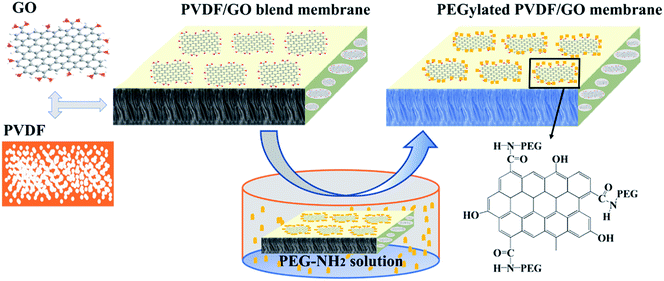
In this study, PVDF/GO blended membranes were first fabricated by non-solvent-induced phase separation (NIPS). Then PEG molecular chains were grafted onto the reactive GO sheets via amination. The surface chemical composition, hydrophilicity, permeability and antifouling performance of the PEGylated PVDF/GO membranes were explored. The results in this work proved that the GO sheets additive can be employed to provide active sites to further modify the porous membranes, and this will be of great significance for subsequent studies.
Experimental
Materials
PVDF (FR-1015) was obtained from Solvay (Shanghai Agency, P. R. China). Graphene oxide was purchased from Yuhuang Technology Co., Ltd. Bovine serum albumin (BSA, Mw = 66.4 × 10³ g mol−1) was obtain from Aladdin Reagent Co., China. Methoxypolyethylene glycols (MPEG, Mw = 750 Da, 99%), 2-(tert-butoxycarbonylamino)-1-ethanol, dioxane (99%), hydrochloric acid (99%), ethyl acetate (99%), trifluoroacetic acid, sodium carbonate (99%), toluene-2,4-diisocyanate (TDI, 99%) and N,N-dimethylacetamide (DMAc, 99%) were purchased from Sinopharm Chemical Reagent. All chemicals were reagent grade.
Synthesis of PEG-NH2
Di-tert-butyloxycarbonate ((BOC)2O, 100 mmol) was dissolved in a suitable amount of 1,4-dioxane as solvent and the solution was added slowly into 100 mmol mono-2-(tert-butoxycarbonylamino)-1-ethanol. The mixture was stirred for one day, then extracted with ethyl acetate and evaporated to provide amino-protected 2-(tert-butoxycarbonylamino)-1-ethanol under ice bath conditions. MPEG (25 mmol) was vacuum dried at 80 °C for 6 h and added into toluene-2,4-diisocyanate (TDI, 25 mmol) at 25 °C. The mixture was kept at 55 °C with stirring for 3 h, and 25 mmol of amino-protected 2-(tert-butoxycarbonylamino)-1-ethanol was added under stirring for 3 h. Trifluoroacetic acid (TFA, 50 mmol) was added to remove the amino-protecting group in order to obtain PEG-NH2 by mechanical stirring for 6 h and evaporating to remove excess solvent. Anhydrous sodium carbonate (K2CO3) and ethyl acetate were added dropwise into the solution until the pH was over 7. A clear yellow thick liquid (PEG-NH2, 24.3 g, Mw = 985.23 Da) was obtained after drying in vacuum.37,38
Fabrication of membranes
PEGylated PVDF/GO membranes were fabricated via a surface grafting method as shown in Scheme 1. PVDF/GO blended membranes were prepared by non-solvent induced phase separation (NIPS).39 PVDF powder was dried in a vacuum oven at 80 °C for 6 h to remove the absorbed water. GO was dispersed in DMAc by sonication for 120 min to prepare a homogeneous solution. Then, 15 wt% PVDF was added to the solution under stirring at 60 °C for 10 h to obtain a casting solution. The solution was evacuated for 5 h and left at room temperature for one day to remove air bubbles. The solution was cast on a glass plate using a 250 μm casting knife, and immediately immersed in a water coagulation bath at room temperature. The fabricated PVDF/GO blended membranes were respectively named M0, M0.5, M1 and M2 according to the weight concentrations of GO in the PVDF powder. PEGylated PVDF/GO membranes were fabricated by the surface grafting technique. In a typical process, M1 was soaked in PEG-NH2 solution (2 g L−1) at 90 °C for 24 h. Then, washed with deionized water, the obtained membrane was dried and named M1-g-PEG.
 |
| | Scheme 1 A schematic illustration of the fabrication of the PEGylated PVDF/GO membranes. | |
Characterization
Raman spectroscopy of GO was conducted using a confocal Raman spectrometer (inVia Reflex, Renishaw, UK) at a wavelength of 532.8 nm. X-ray photoelectron spectroscopy (XPS; Kratos Analytical, UK) was used to study the surface chemical compositions of the membranes. UV-vis spectra were recorded using a Lambda 950 UV-vis spectrometer (PerkinElmer, USA). The functional groups and chemical structures of the membranes were characterized by Fourier transform infrared spectroscopy-attenuated total reflectance (FTIR-ATR; Cary 660 + 620, USA) at room temperature. The surface and cross-sectional morphologies of the membranes were examined by thermal field emission scanning electron microscopy (TFESEM; Verios G4 UC, Thermo Scientific, USA). To prepare the SEM samples, the membranes were cut into small pieces and immersed in liquid nitrogen for 60–90 s. The frozen membranes were snapped with a pair of tweezers. After drying at room temperature, the samples were adhered to the TFSEM sample holder with conductive tape and a thin Pt layer was sputtered on. The roughness of each membrane surface was observed by atomic force microscopy (AFM; Dimension 3100, Vecco, USA) with an area of 3 μm × 3 μm.
Water contact angle (WCA) measurements
WCA was measured using a contact angle measuring device (OCA 20, Dataphysics, Germany) based on the sessile drop method. The sample was dried at room temperature for 6 h. Deionized water (2 μL) was dripped onto the surface of the flat membrane using a micro syringe. The initial water contact angle on the surface was measured. The contact angles were measured at least 7 times at random positions on each membrane to obtain a reliable average value.
Water flux and antifouling performance
The antifouling experiment was divided into three parts. The membrane was cut into a circle of suitable size and then fixed on the sample holder of a dead-end stirred filtration cell (Millipore Corporation, XFUF04701, USA) with an effective area of 14.2 cm2. At room temperature, the membrane was first compacted at a pressure of 2 bar for 1 h to obtain a stable flow. The pressure was reduced to 1 bar, and the deionized water flow rate was recorded every minute. The corresponding water flux was calculated according to eqn (1) and named J1. Then, 0.8 g L−1 BSA solution in physiological saline was permeated through the membrane sample at a stirring rate of 500 rpm to minimize concentration polarization. After filtering for 30 min at 1 bar, BSA flux (J2) was calculated. After BSA solution filtration, the membrane was washed with physiological saline under shaking for 24 h. Finally, the deionized water was again pushed through the cleaned membrane, and water flux was measured again and recorded as J3.| |
 | (1) |
where J (L m−2 h−1) is the flux, V (L) is the volume of the collected liquid, S (14.2 cm2) is the effective area, and t is the running time of the liquid.
The protein rejection (R) was calculated using the equation:
| |
 | (2) |
where
C1 and
C2 are the BSA concentrations of permeate and feed solutions, respectively. They were measured with a UV-vis spectrophotometer (Lambda 950, PerkinElmer, USA) at 280 nm.
The antifouling performance of the membrane was evaluated by flux recovery rate (FRR), total fouling ratio (Rt), reversible fouling rate (Rr) and irreversible fouling rate (Rir).
| |
 | (3) |
| |
 | (4) |
| |
 | (5) |
| |
 | (6) |
Results and discussion
Surface compositions of the membranes
XPS measurement was used to identify the chemical compositions of the membrane surfaces, and typical results and spectra are presented in Table 1 and Fig. 1, respectively. It can be observed that the wide scan of M1 contains the elements C, N, O and F. After introducing GO, the content of the element F declines from 51.5% (M0) to 31.5% (M1), while the O percentage rises from 0.2% (M0) to 9.1% (M1). This is caused by the high percentage of C and O in GO. It should be noticed that N of M1 (1.8%) may originate from the original GO material. For M1-g-PEG, the O concentration increases to 14.8%. To provide more information concerning the chemical changes of the membrane surfaces, the C1s core-level spectrum of M0 was resolved into peaks including C–H, CH2–CF2 and CF2 (Fig. 1B). In Fig. 1C, the C1s core-level spectrum of M1 was resolved into five peaks, derived from C–H, CH2–CF2 plus C–C, C–O, C![[double bond, length as m-dash]](https://www.rsc.org/images/entities/char_e001.gif) O and CF2. The peaks for CH2–CF2 and C–C coincide, and the C–O and CO peaks belong to the GO sheets. For M1-g-PEG, a new C–N peak at 285.7 eV appears (Fig. 1D). All results indicate that PEGylated PVDF membranes have been successfully fabricated with the aid of the reactive GO sheets additive.
O and CF2. The peaks for CH2–CF2 and C–C coincide, and the C–O and CO peaks belong to the GO sheets. For M1-g-PEG, a new C–N peak at 285.7 eV appears (Fig. 1D). All results indicate that PEGylated PVDF membranes have been successfully fabricated with the aid of the reactive GO sheets additive.
Table 1 Surface compositions of M0, M1 and M1-g-PEG
| Sample |
C1s (mol%) |
F1s (mol%) |
O1s (mol%) |
N1s (mol%) |
| M0 |
48.3 |
51.5 |
0.2 |
— |
| M1 |
57.6 |
31.5 |
9.1 |
1.8 |
| M1-g-PEG |
51.5 |
30.6 |
14.8 |
3.1 |
 |
| | Fig. 1 XPS wide scans (A) and C1s core-level spectra of M0 (B), M1 (C), and M1-g-PEG (D). | |
Raman spectroscopy is an effective method for characterizing the structure of carbon materials. As shown in Fig. 2A, M0 has no apparent Raman signal in the range of 800–2000 cm−1. In contrast, GO exhibits a D band at 1347 cm−1 and a G band at 1558 cm−1. The broad D band suggests that some carbon atoms of GO have been converted into sp3 hybrid structure. The D band variation may be a structural defect caused by epoxides and hydroxyl groups on the carbon-based surface, and the G band is caused by the in-plane displacement of carbon atoms in the hexagonal carbon sheet. In the Raman spectra of M1 and M1-g-PEG, D and G bands are observed. Generally, the intensity ratio of the D band to the G band (ID/IG) is used to evaluate the degree of defects in the carbon materials. The ratio of ID/IG increases from 0.90 (M0) to 0.93 (M1) and 0.99 (M1-g-PEG), indicating that the functional groups of GO on the surfaces of the membrane were reacted or eliminated. So, this indicates that the epoxy group and carboxyl group of GO may react with PEG-NH2. Raman map-scanning test images of the membranes at 50 × 50 μm under the G peak range of GO are shown in Fig. 2B–F. In contrast to M0, the PVDF/GO blended membranes produce colored images, indicating GO sheets have been immobilized on the membranes. And the color changes from blue (M0.5) to green (M1) and red (M2), indicating high GO concentration on the surfaces. In addition, the color of the images remains consistent over a large area, indicating that GO is distributed homogeneously on the surfaces. In Fig. 2F, the surface sweeping color of M1-g-PEG is lighter than that of M1 (Fig. 2D), indicating less GO on the membrane surface after grafting the PEG-NH2 molecular chains.
 |
| | Fig. 2 Raman spot-scanning (A) and map-scanning images of M0 (B), M0.5 (C), M1 (D), M2 (E) and M1-g-PEG (F). | |
FTIR-ATR spectra of MPEG and PEG-NH2 are shown in Fig. 3A. In the spectrum of MPEG, O–H at 3400 cm−1 and the skeleton peak C–H at 2854 cm−1 are observed. For PEG-NH2, new peaks due to N–H at 3400 cm−1, C–H at 2854 cm−1, CO at 1715 cm−1 and aromatic CC at 1623 cm−1 are present. This indicates that MPEG was aminated successfully. In addition, FTIR-ATR spectra of the fabricated membranes (M0, M1 and M1-g-PEG) are shown in Fig. 3B. In contrast to M0, M1 exhibits the absorption peak of the graphene skeleton at 1620 cm−1. For M1-g-PEG, the characteristic peaks at 3400 and 2854 cm−1 derived from PEG are detected, and new peaks at 1645 and 1542 cm−1 are attributed to the amide bonds. The results indicate that PEG chains have been grafted onto the surface of PVDF/GO blended membranes.
 |
| | Fig. 3 FTIR-ATR spectra of MPEG and PEG-NH2 (A) and the membranes of M0, M1 and M1-g-PEG (B). | |
Membrane morphologies
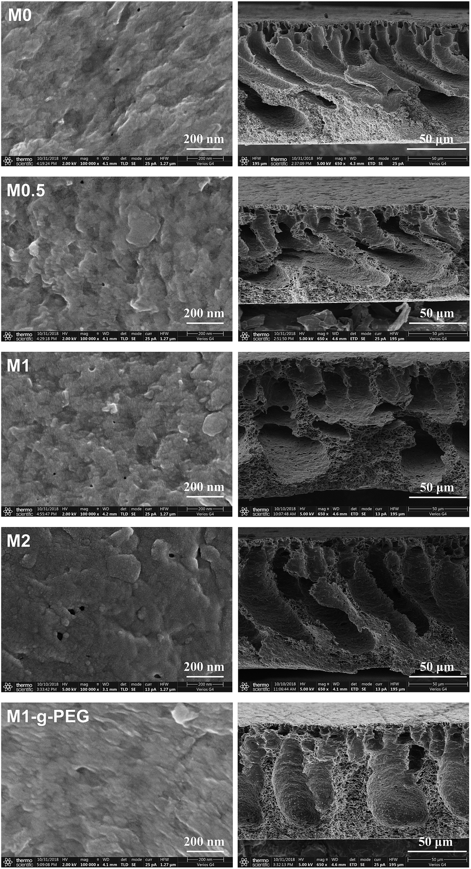
Fig. 4 displays the surface and cross-section SEM images of M0, M0.5, M1, M2 and M1-g-PEG. From the surface images, with the increase of GO content, the pores of the fabricated PVDF/GO blended membranes enlarge. After grafting PEG molecular chains on the surface of M1, the membrane becomes dense. From the cross-sectional images, a typical asymmetric porous structure is divided into two parts, “finger” holes extending from the surface and a dense “sponge” substrate. The asymmetric structure is due to the polymer concentration gradient of the liquid film in a water bath. When the casting solution is immersed, the outer surface of the membranes is immediately solidified, resulting in the formation of dense skin. The solvent present in the casting solution also rapidly diffuses outward, and the diffusion of water causes the membranes to coagulate to create long “finger” holes extending from the surface. As the phase inversion continues, this delamination process between the solvent and water gradually slows down owing to the solidification of the liquid film. As a result, the phase inversion process is inhibited, leading to dense “sponge” pores.40
 |
| | Fig. 4 Open side surface and cross-section SEM images of the membranes. | |
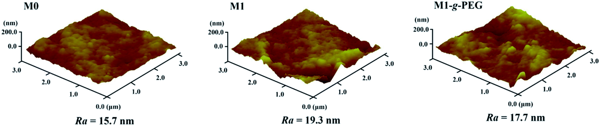
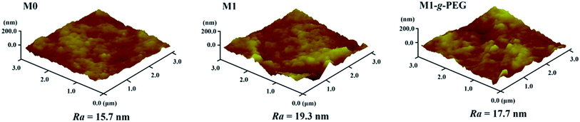
Fig. 5 shows the three-dimensional AFM images of M0, M1 and M1-g-PEG. The roughness parameter Ra of the membranes was calculated based on the AFM scan area of 3 μm × 3 μm. Compared with M0, more “peaks” are observed on M1 (Ra = 19.3 nm), indicating a rougher surface. In contrast, the roughness of M1-g-PEG is reduced to 17.7 nm owing to the PEG chains grafted on the membrane surface. After grafting onto the surface of M1, PEG-NH2 molecular segments covered or lapped on the surface, resulting in the reduction of the roughness of the membrane.
 |
| | Fig. 5 AFM images of M0, M1 and M1-g-PEG. | |
Hydrophilicity of membranes
Water contact angle is used to characterize the hydrophilicity of the membranes. Hydrophilicity is one of the most important properties of membranes because it affects their flux and antifouling performance. As shown in Fig. 6, the contact angle of M1 was as high as 90°, indicating poor hydrophilicity. The hydrophilicity increased after the hydrophilic GO sheets were added, and the water content angle of M1-g-PEG achieved 59.9°. A hydrophilic layer will be formed between the hydrophilic membrane surface and water for further promoting liquid permeability and antifouling performance.
 |
| | Fig. 6 The water contact angles of M0, M0.5, M1, M2 and M1-g-PEG. | |
Water flux and antifouling performance of the membranes
Pure water flux (J1) and BSA rejection (R) of the fabricated membranes were characterized by using a dead-end stirred filter at 1 bar pressure, and the results are shown in Fig. 7A and B. As seen, the water flux of PVDF/GO blended membranes is higher than that of M0.41 J1 increases from 17.7 to 32.5 L m−2 h−1 when the GO sheets content increases from 0 to 2 wt%. J1 of M1-g-PEG is lower than that of other membranes, while R is as high as 93.4%, owing to its dense surface (Fig. 4). Moreover, BSA was used as the model foulant to characterize the antifouling performances of the membranes before and after surface modification.27,42,43 As shown in Fig. 7C, for the fabricated PVDF/GO membranes, FRR increases from 56.6 to 86.0% and Rt decreases from 51.1 to 26.7% when the content of GO rises from 0 to 1 wt%. After surface PEGylation, FRR of M1-g-PEG achieves 90.2%, while Rt is as low as 20.7%. The smaller Rt indicates less protein adsorbs to or deposits on the membrane surfaces. In addition, the ratio of reversible fouling rate to the total fouling rate (Rr/Rt) of M1-g-PEG is higher than that of other membranes (Fig. 7D). M1-g-PEG has not only lower Rt but also lower Rir during BSA filtration, and the reversible fouling is the dominant factor responsible for the flux loss, the smaller Rt and Rir values, and the better antifouling performance of the membranes. The improvement in the antifouling performance of PVDF membranes is mainly attributed to the enhanced hydrophilicity. Hydrophilic groups of PEG and the remaining hydroxyl/carboxyl groups of GO may interact with water molecules through van der Waals forces and hydrogen bonds forming a water molecular layer on M1-g-PEG surface to prevent or reduce BSA adhesion/deposition, resulting in high antifouling performance.27,44 Compared with the membrane data in some literature (Table 2), the antifouling performance and hydrophilicity of M1-g-PEG are better. And the reversible fouling plays a dominant role during the membrane fouling process.
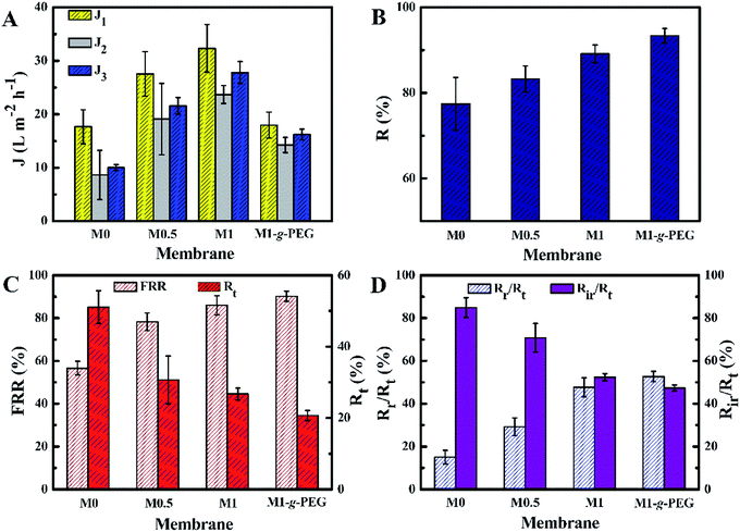 |
| | Fig. 7 (A) Pure water flux (J1), BSA solution flux (J2) and recovered pure water flux (J3); (B) water flux recovery rate (FRR) and total fouling rate (Rt); (C) protein rejection (R); and (D) the ratio of the reversible fouling rate (Rr) and irreversible fouling rate (Rir) to the total fouling rate (Rr/Rt and Rir/Rt). | |
Table 2 Comparative results of water flux recovery, total fouling rate and water contact angle of the membranes
| Sample |
FRR (%) |
Rt (%) |
Water contact angle (°) |
Reference |
| PVDF/GO |
85.1 |
— |
66.5 |
27 |
| PVDF/Al2O3 |
70.0 |
— |
70.2 |
45 |
| PVDF/GO |
88.56 |
— |
60.5 |
46 |
| PVDF/GO |
75.4 |
24.0 |
— |
47 |
| M1-g-PEG |
90.2 |
20.7 |
60.1 |
This work |
Conclusions
In this work, a PVDF/GO blended membrane and its PEGylated membrane formed by grafting PEG onto the graphene oxide additive were prepared via NIPS with the aim of improving the permeability and antifouling performance. The addition of GO sheets significantly promoted the water flux and hydrophilicity of PVDF membranes, and improved the antifouling performance. Furthermore, the functional groups of GO sheets can act as reactive sites for the immobilization of hydrophilic PEG chains. After surface PEGylation, the hydrophilicity of M1-g-PEG was further enhanced; the water contact angle was reduced to 59.9°. Moreover, FRR of M1-g-PEG increased to 90.2%, while Rt decreased to 20.7% compared with non-modified PVDF membrane. The results indicated that the fabricated PEGylated PVDF/GO membranes exhibited enhanced hydrophilicity and antifouling performance. This work provides a valuable strategy to fabricate PEGylated membranes via the introduction of a reactive GO additive into the membrane matrix.
Conflicts of interest
The authors declare no potential conflicts of interest with respect to the research, authorship, and/or publication of this article.
Acknowledgements
This study was supported by the National Science Foundation of China (No. 51603214), the National Science and Technology Bureau (No. 2018A610110), and the “One hundred Talented People” of Chinese Academy of Sciences (No. Y60707WR04).
References
- A. M. Omer, Water resources and freshwater ecosystems in Sudan, Renewable Sustainable Energy Rev., 2008, 12, 2066–2091 CrossRef.
- M. Floerke and E. Kynast, et al., Domestic and industrial water uses of the past 60 years as a mirror of;socio-economic development: A global simulation study, NATO ASI Ser., Ser. I, 2013, 23, 144–156 Search PubMed.
- B. Tang and Z. Zhang, Essence of disposing the excess sludge and optimizing the operation of wastewater treatment: rheological behavior and microbial ecosystem, Chemosphere, 2014, 105, 1–13 CrossRef CAS.
- G. Asman and O. Şanlı, Characteristics of Permeation and Separation for Acetic Acid–Water Mixtures Through Poly(Vinyl Alcohol) Membranes Modified with Poly(Acrylic Acid), Sep. Sci. Technol., 2003, 38, 1963–1980 CrossRef CAS.
- S. Simone, A. Figoli and S. Santoro, et al., Preparation and characterization of ECTFE solvent resistant membranes and their application in pervaporation of toluene/water mixtures, Sep. Sci. Technol., 2012, 90, 147–161 CAS.
- Q. H. She, L. N. Chi and W. L. Zhou, et al., Overview of forward osmosis membrane separation technology: research and its application to water treatment, Environ. Sci. Technol., 2010, 33, 117–122 CAS.
- R. Kiełczyński and M. Bryjak, Molecularly imprinted membranes for cinchona alkaloids separation, Sep. Sci. Technol., 2005, 41, 231–235 Search PubMed.
- J. Zhao, K. Zhang and D. Gao, et al., Optimization of BaxSr1-xCo0.9Nb0.1O3-delta perovskite as oxygen semi-permeable membranes by compositional tailoring, Sep. Sci. Technol., 2010, 71, 152–159 CAS.
- Y. N. Wang and C. Y. Tang, Protein fouling of nanofiltration, reverse osmosis, and ultrafiltration membranes—The role of hydrodynamic conditions, solution chemistry, and membrane properties, J. Membr. Sci., 2011, 376, 275–282 CrossRef CAS.
- S. Ramakrishna, Z. Ma, and T. Matsuura, Membrane and Membrane Separation Process, 2014 Search PubMed.
- T. Yuan, J. Meng and T. Hao, et al., A scalable method toward superhydrophilic and underwater superoleophobic PVDF membranes for effective oil/water emulsion separation, ACS Appl. Mater. Interfaces, 2015, 7, 14896–14904 CrossRef CAS.
- Y. Zhang, W. Yu and R. Li, et al., Novel conductive membranes breaking through the selectivity-permeability trade-off for Congo red removal, Sep. Purif. Technol., 2019, 211, 368–376 CrossRef CAS.
- A. C. Hinckley, C. Wang and R. Pfattner, et al., Investigation of a Solution-Processable, Nonspecific Surface Modifier for Low Cost, High Work Function Electrodes, ACS Appl. Mater. Interfaces, 2016, 8, 19658–19664 CrossRef CAS.
- Y. Chen, J. Teng and L. Shen, et al., Novel insights into membrane fouling caused by gel layer in a membrane bioreactor: Effects of hydrogen bonding, Bioresour. Technol., 2019, 276, 219–225 CrossRef CAS PubMed.
- J. Teng, M. Zhang and K. T. Leung, et al., A unified thermodynamic mechanism underlying fouling behaviors of soluble microbial products (SMPs) in a membrane bioreactor, Water Res., 2019, 149, 477–487 CrossRef CAS.
- M. Mondal and S. De, Preparation and characterization of PDMS-PVDF hydrophobic microporous membrane for membrane distillation, Desalination, 2015, 370, 63–71 CrossRef.
- W. Yu, Y. Liu and Y. Xu, et al., A conductive PVDF-Ni membrane with superior rejection, permeance and antifouling ability via electric assisted in situ aeration for dye separation, J. Membr. Sci., 2019, 581, 401–412 CrossRef CAS.
- J. Li, J. Miao, X. Shao and Y. Xu, et al., Surface modification of PVDF porous membranes, Chin. J. Polym. Sci., 2013, 31, 994–1001 CrossRef CAS.
- X. Huang, W. Wang and Y. Liu, et al., Treatment of oily waste water by PVP grafted PVDF ultrafiltration membranes, Chem. Eng. J., 2015, 273, 421–429 CrossRef CAS.
- S. Gong, H. Jeon and H. Lee, et al., Effects of an Integrated Separator/Electrode Assembly on Enhanced Thermal Stability and Rate Capability of Lithium-Ion Batteries, ACS Appl. Mater. Interfaces, 2017, 9, 17814–17821 CrossRef CAS PubMed.
- L. Shen, Y. Zhang and W. Yu, et al., Fabrication of hydrophilic and antibacterial poly(vinylidene fluoride) based separation membranes by a
novel strategy combining radiation grafting of poly(acrylic acid) (PAA) and electroless nickel plating, J. Colloid Interface Sci., 2019, 543, 64–75 CrossRef CAS PubMed.
- Y. Zhao, W. Yu and R. Li, et al., Electric field endowing the conductive polyvinylidene fluoride (PVDF)-graphene oxide (GO)-nickel (Ni) membrane with high-efficient performance for dye wastewater treatment, Appl. Surf. Sci., 2019, 483, 1006–1016 CrossRef CAS.
- S. Wongchitphimon, R. Wang and R. Jiraratananon, et al., Effect of polyethylene glycol (PEG) as an additive on the fabrication of polyvinylidene fluoride-co-hexafluropropylene (PVDF-HFP) asymmetric microporous hollow fiber membranes, J. Membr. Sci., 2011, 369, 329–338 CrossRef CAS.
- D. Pozzi, V. Colapicchioni and G. Caracciolo, et al., Effect of polyethyleneglycol (PEG) chain length on the bio-nano-interactions between PEGylated lipid nanoparticles and biological fluids: from nanostructure to uptake in cancer cells, Nanoscale, 2014, 6, 2782–2792 RSC.
- N. S. Kacem, F. Delporte and Y. Muhovski, et al., In vitro screening of durum wheat against water-stress mediated through polyethylene glycol, Genet. Eng. Biotechnol. J., 2017, 15, 237–247 Search PubMed.
- K. Thuresson, F. E. Antunes and M. G. Miguel, et al., The association between a non-ionic microemulsion and hydrophobically modified PEG. A rheological investigation, Prog. Colloid Polym. Sci., 2004, 123, 40–43 CAS.
- J. Zhang, Z. Xu and W. Mai, et al., Improved hydrophilicity, permeability, antifouling and mechanical performance of PVDF composite ultrafiltration membranes tailored by oxidized low-dimensional carbon nanomaterials, J. Mater. Chem. A, 2013, 1, 3101–3111 RSC.
- M. Yang, L. Wang and T. Hou, et al., Controlling of the electronic properties of WS2 and graphene oxide heterostructures from first-principles calculations, J. Mater. Chem. C, 2016, 5, 201–207 RSC.
- A. Falin, Q. Cai and S. Ejg, et al., Mechanical properties of atomically thin boron nitride and the role of interlayer interactions, Nat. Commun., 2017, 8, 15815–15823 CrossRef CAS PubMed.
- Z. Wang and B. Mi, Environmental Applications of 2D Molybdenum Disulfide (MoS2) Nanosheets, Environ. Sci. Technol., 2017, 51, 8229–8244 CrossRef CAS PubMed.
- X. Song, J. Hu and H. Zeng, Two-dimensional semiconductors: recent progress and future perspectives, J. Mater. Chem. C, 2013, 1, 2952–2969 RSC.
- J. Zhu, J. Wang and J. Hou, et al., Graphene-based antimicrobial polymeric membranes: a review, J. Mater. Chem. A, 2017, 5, 6676–6793 Search PubMed.
- Y. He, R. Hu and Y. Zhong, et al., Graphene oxide as a water transporter promoting germination of plants in soil, Nano Res., 2018, 11, 1928–1937 CrossRef CAS.
- W. Yu, Y. Liu, Y. Xu, R. Li, J. Chen, B.-Q. Liao, L. Shen and H. Lin, J. Membr. Sci., 2019, 581, 401–412 CrossRef CAS.
- Z. Wang, H. Yu and J. Xia, et al., Novel GO-blended PVDF ultrafiltration membranes, Desalination, 2012, 299, 50–54 CrossRef CAS.
- Z. J. Jiang, Z. Jiang and X. Tian, et al., Sulfonated Holey Graphene Oxide (SHGO) Filled Sulfonated Poly(ether ether ketone) Membrane: The Role of Holes in the SHGO in Improving Its Performance as Proton Exchange Membrane for Direct Methanol Fuel Cells, ACS Appl. Mater. Interfaces, 2017, 9, 20046–20056 CrossRef CAS PubMed.
- Y. Hu, Y. Wang and Z. Zeng, et al., PEGlated Graphene as Nanoadditive for Enhancing the Tribological Properties of Water-based Lubricant, Carbon, 2018, 137, 41–48 CrossRef CAS.
- S. Zalipsky, Functionalized poly(ethylene glycol) for preparation of biologically relevant conjugates, ChemInform, 1995, 26, 150–165 Search PubMed.
- D. Y. Zuo, B. K. Zhu and J. H. Cao, et al., Influence of Alcohol-Based Nonsolvents on the Formation and Morphology of PVDF Membranes in Phase Inversion Process, Chin. J. Polym. Sci., 2006, 24, 281–289 CrossRef CAS.
- N. Meng, R. C. E. Priestley and Y. Zhang, et al., The effect of reduction degree of GO nanosheets on microstructure and performance of PVDF/GO hybrid membranes, J. Membr. Sci., 2016, 501, 169–178 CrossRef CAS.
- M. Na, R. C. E. Priestley and Y. Zhang, et al., The effect of reduction degree of GO nanosheets on microstructure and performance of PVDF/GO hybrid membranes, J. Membr. Sci., 2016, 501, 169–178 CrossRef.
- V. Vatanpour, S. S. Madaeni and L. Rajabi, Boehmite nanoparticles as a new nanofiller for preparation of antifouling mixed matrix membranes, J. Membr. Sci., 2012, 401–402, 132–143 CrossRef CAS.
- L. Zhu, F. Liu and X. Yu, et al., Poly(Lactic Acid) Hemodialysis Membranes with Poly(Lactic Acid)-block-Poly(2-Hydroxyethyl Methacrylate) Copolymer As Additive: Preparation, Characterization, and Performance, ACS Appl. Mater. Interfaces, 2015, 7, 17748–17755 CrossRef CAS PubMed.
- Z. Xu, J. Zhang and M. Shan, et al., Organosilane-functionalized graphene oxide for enhanced antifouling and mechanical properties of polyvinylidene fluoride ultrafiltration membranes, J. Membr. Sci., 2014, 458, 1–13 CrossRef CAS.
- L. Yan, Y. S. Li and C. B. Xiang, et al., Effect of nano-sized Al2O3 -particle addition on PVDF ultrafiltration membrane performance, J. Membr. Sci., 2006, 276, 162–167 CrossRef CAS.
- C. Zhao, X. Xu and C. Jie, et al., Effect of graphene oxide concentration on the morphologies and antifouling properties of PVDF ultrafiltration membranes, J. Environ. Chem. Eng., 2013, 1, 349–354 CrossRef CAS.
- S. Ayyaru and Y. H. Ahn, Application of sulfonic acid group functionalized graphene oxide to improve hydrophilicity, permeability, and antifouling of PVDF nanocomposite ultrafiltration membranes, J. Membr. Sci., 2017, 525, 210–219 CrossRef CAS.
|
| This journal is © The Royal Society of Chemistry 2019 |
Click here to see how this site uses Cookies. View our privacy policy here. 
 Open Access Article
 This Open Access Article is licensed under a Creative Commons Attribution-Non Commercial 3.0 Unported Licence
 *b and
Haichao Zhao
*b and
Haichao Zhao