
 Open Access Article
 This Open Access Article is licensed under a Creative Commons Attribution-Non Commercial 3.0 Unported Licence
Plasma treated TiO2/C nanofibers as high performance anode materials for sodium-ion batteries†
Rui Wang *,
Shuimei Chen*,
Daming Ren,
Songting Liu,
Beibei He,
Yansheng Gong and
Huanwen Wang
*,
Shuimei Chen*,
Daming Ren,
Songting Liu,
Beibei He,
Yansheng Gong and
Huanwen Wang
Faculty of Materials Science and Chemistry, China University of Geosciences, Wuhan 430074, China. E-mail: wangrui@cug.edu.cn; chensm920420@cug.edu.cn
First published on 11th June 2019
Abstract
TiO2 has been a promising anode material for sodium-ion batteries because it is low-cost and environment-friendly. However, its electrochemical performance at high rates is still not acceptable. Herein, we synthesized a TiO2/C nanofiber material by the electrospinning method, and introduced air plasma treatments to modify the obtained material. Characterization results indicate that after the plasma treatments, the C fibers may have reacted with the plasma, and the surface areas of the nanofibers are increased. Electrochemical tests show this plasma treatment may be beneficial to the rate performance. The TiO2/C nanofiber with plasma treatment could deliver a high redox capacity of 191 mA h g−1 after 500 cycles at a very high rate of 10C (3300 mA g−1). The superior effects of the plasma treatment on the rate performance may provide new insights for developing better materials for practical sodium-ion batteries.
1. Introduction
With the rapid development of consumer electronics and electrical vehicles, lithium-ion batteries (LIBs) have been widely researched and are in frequent use nowadays.1–7 However, the potential limit and high cost of lithium resources are still big concerns, which may hinder the applications of LIBs in large-scale energy storage systems. Recently, with the advantage of low-cost and widespread availability of sodium resources, sodium-ion batteries (SIBs) have become an important and competitive option for electrical storage applications.8–14 However, in SIBs, since the radius of the Na ion is 43% larger than that of the Li ion, it is more difficult to find suitable electrode materials to accommodate sodium ions and achieve rapid and reversible ion insertion/extraction. Recently, many efforts have been made to find suitable anode materials for SIBs.15–17 As to the carbon based materials, most of them have irreversible reactions with sodium.18 Only a few hard carbons were reported to have attractive sodium storage performance, but their low potential and large polarization are still big concerns for battery applications.19,20 The alloying anodes such as Sb, Sn, and P, are other types of anode candidates and have shown high reversible capacities.21–23 However, the large volume change during cycles is a big obstacle, which leads to electrode pulverization, capacity loss and poor cycling performance.24 Therefore, searching for low cost, reasonable performance anodes is still a great challenge in SIBs.TiO2 is a low-cost, abundant, and environment-friendly material, which has shown large reversible capacity and good cyclability in LIBs. Recently, it is also proposed to be used as anode materials in SIBs, but the insulating nature of TiO2 is still a big problem, which may result in a poor electrochemical performance, especially the rate performance.25 TiO2 has many structures, and the sodium storage capabilities of polymorphs such as amorphous,26 anatase,27 and rutile28,29 have been studied. Though their performances exhibit a large diversity, most of them deliver capacities lower than 200 mA h g−1, only a few of them can deliver a capacity higher than 250 mA h g−1 (about 0.76C). In order to improve the rate performance, previous reports have suggested to make one-dimensional nanosized materials. Xiong et al. developed an electrospinning technique to prepare TiO2/C nanofibers, and the material can deliver a capacity of 164.9 mA h g−1 at a current density of 2000 mA g−1.30 Ge et al. prepared TiO2@CNF composites at different temperatures, and their results indicated the material prepared at 550 °C presented higher capacity retention, while the material prepared at 650 °C possessed better rate capability.31 Wu and coworkers introduced nitrogen doping to the electrospun TiO2/C nanofibers, and improved the capacity from 87 to 108 mA h g−1 at the rate of 10C.32 These results suggest that electrospinning is an effective method to make one dimensional TiO2/C fibers with improved performances.
Recently, the plasma-based technique has been applied to modify the surface of various materials. It has several advantages such as effective, pollution-free, uniform, and reproducible.33,34 In particular, if carbon-based material is treated and oxygen is involved as a working gas, the surface will be etched and become rougher.35 Liu et al. reported that in addition to etching the surface of the material, the biggest feature of plasma process is the generation of new structures, including edge-dangling bonds, defects and oxygen-containing functional groups, which may contribute to the conductivity of carbon materials.36 Lu et al. mentioned that oxygen-containing functional groups, such as C![[double bond, length as m-dash]](https://www.rsc.org/images/entities/char_e001.gif) O and C–O, played an important role in catalytic activity.37 In this case, it is interesting to modify materials with this plasma technique and observe their electrochemical performances. In this work, we used the electrospinning method to prepare TiO2/C nanofibers. Then the air plasma treatment was employed to modify the fibers and its effect on the electrochemical properties was investigated in details.
O and C–O, played an important role in catalytic activity.37 In this case, it is interesting to modify materials with this plasma technique and observe their electrochemical performances. In this work, we used the electrospinning method to prepare TiO2/C nanofibers. Then the air plasma treatment was employed to modify the fibers and its effect on the electrochemical properties was investigated in details.
2. Experimental
2.1 Preparation of materials
TiO2/C nanofibers were prepared by the electrospinning technique with different precursor solutions. For TiO2/C nanofibers, 0.75 g polyvinylpyrrolidone (PVP, Mw = 1![[thin space (1/6-em)]](https://www.rsc.org/images/entities/char_2009.gif) 300000) was dissolved in 10 mL ethanol (≥99.9%) at vigorous stirring for 6 h, then a mixture of 2 mL tetrabutyltitanate (Ti(OC4H9)4) and 2 mL acetic acid was dripped in. After stirring for 3 h, the obtained solution was used as the precursor solution.
300000) was dissolved in 10 mL ethanol (≥99.9%) at vigorous stirring for 6 h, then a mixture of 2 mL tetrabutyltitanate (Ti(OC4H9)4) and 2 mL acetic acid was dripped in. After stirring for 3 h, the obtained solution was used as the precursor solution.
In the electrospinning experiment, the precursor solution was loaded into a 10 mL syringe and the flow rate of solution was set to 9 mL h−1 by a syringe pump. A high-voltage power supply was connected to the needle in order to apply a positive voltage of 12 kV and negative voltage of 2.5 kV between the needle and the collector for the formation of nanofibers. As prepared nanofibers were first heated in a muffle furnace at 200 °C in air for 2 h at a heating rate of 0.5 °C min−1, and then calcined in a tube furnace at 550 °C in Ar atmosphere for 3 h. Finally, a film composed of nanofibers was obtained, and is marked as TC.
The plasma treatment was carried on in a plasma equipment (PDC-MG, Mingheng, China). In a typical treating process, the obtained film was fixed on a glass plate in the chamber. The chamber was degassed to 100 Pa and then dry air was led into the reactor. The experimental power input from RF generator was 130 W and the treatment time is 3 min for each side of the film, and the obtained sample is marked as P-TC.
2.2 Materials characterization
X-ray diffraction (XRD) data were collected on a Bruker D8 X-ray diffractor using Cu Kα radiation (λ = 1.5406 Å). The morphologies of the prepared nanofibers were characterized by scanning electron microscopy (SEM, SU8010, Hitachi, Japan) and transmission electron microscopy (TEM, JEM-2100F, Japan). X-ray photoelectron spectroscopy (XPS) was employed on a Multilab 2000 to investigate the valence states of the surface atoms. Nitrogen adsorption–desorption isotherms (BET) were obtained on a Micromeritics ASAP 2460 instrument. Thermo-gravimetric measurement (TGA) was conducted on a STA 449 F3 Jupiter thermogravimetric analyzer (Netzsch, German).2.3 Electrochemical characterization
For electrochemical measurements, the TC or P-TC nanofibers were milled into powders and made into electrodes. The electrodes were composed of nanofibers, super P and PVDF at a weight ratio of 8:1:1. Cu foil was used as current collector, and the diameter of each electrode is 12 mm. The average mass loading is ∼1 mg cm−2. CR2032 coin cells were assembled in a glovebox filled with high purity argon atmosphere (O2 and H2O < 0.05 ppm). A sodium foil was used as both counter and reference electrode, and glass fiber (Whatman) was used as the separator. The electrolyte was 1 M NaClO4 in propylene carbonate (PC) and ethylene carbonate (EC) with a volume ratio of 1:1. All the cells were cycled using a Land automatic battery tester. Electrochemical impedance spectroscopy (EIS) were measured on a Gamry Reference 3000 electrochemical workstation at the open circuit potential in the frequency range from 1 MHz to 0.01 Hz.
3. Results and discussion
The XRD patterns of TiO2/C (TC) and Plasma-TiO2/C (P-TC) nanofibers are shown in Fig. 1. The main XRD peaks of each sample can be indexed to the (101), (200), (105), (211), and (204) planes, corresponding to anatase TiO2 (JCPDS no. 021-1272). Besides, a bump at around 22° can also be observed, and it is related to the carbon fibers.38 The TGA results of the TC and P-TC sample are shown in Fig. S1.† It can be seen that the carbon contents in all two samples are about 18.0% and 18.6%, respectively.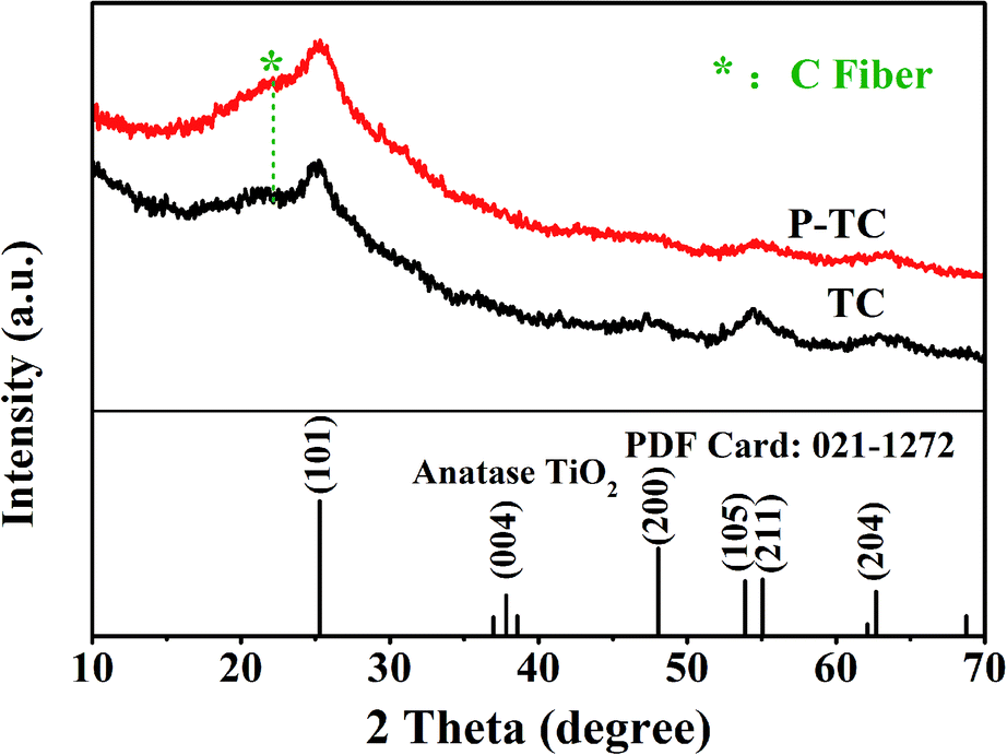 | ||
| Fig. 1 XRD patterns of the TiO2/C (TC) and Plasma-TiO2/C (P-TC) samples. | ||
The morphology and microstructure of the two samples are demonstrated via SEM. SEM images in Fig. 2a and b show that TC and P-TC nanofibers all display a connected network-like structure, with a uniform diameter distribution of about 400 nm. However, the slight changes can be observed from their morphologies at a high magnification in Fig. 2c and d. After plasma treatment, surfaces of the fibers became rougher, and this may be the result of the plasma etching.
 | ||
| Fig. 2 SEM images of the TC and P-TC samples at low magnification (a and b) and high magnification (c and d). | ||
The results of Brunauer–Emmett–Teller (BET) surface area and pore size distribution measured by N2 adsorption–desorption isotherms are shown in Fig. 3. As shown in Fig. 3a, the surface area of TC is determined to be 89 m2 g−1. After the plasma treatment, the surface area changes to 118 m2 g−1 in Fig. 3b. This means the surface of fibers have been corroded by the plasma and the area was increased by 33%. It can be seen from Fig. 3c–d that the pore size distribution of the two are similar, with the pore size mainly between 10 and 40 nm. But the content of pores with the size around 10 nm increases slightly after the plasma treatment.
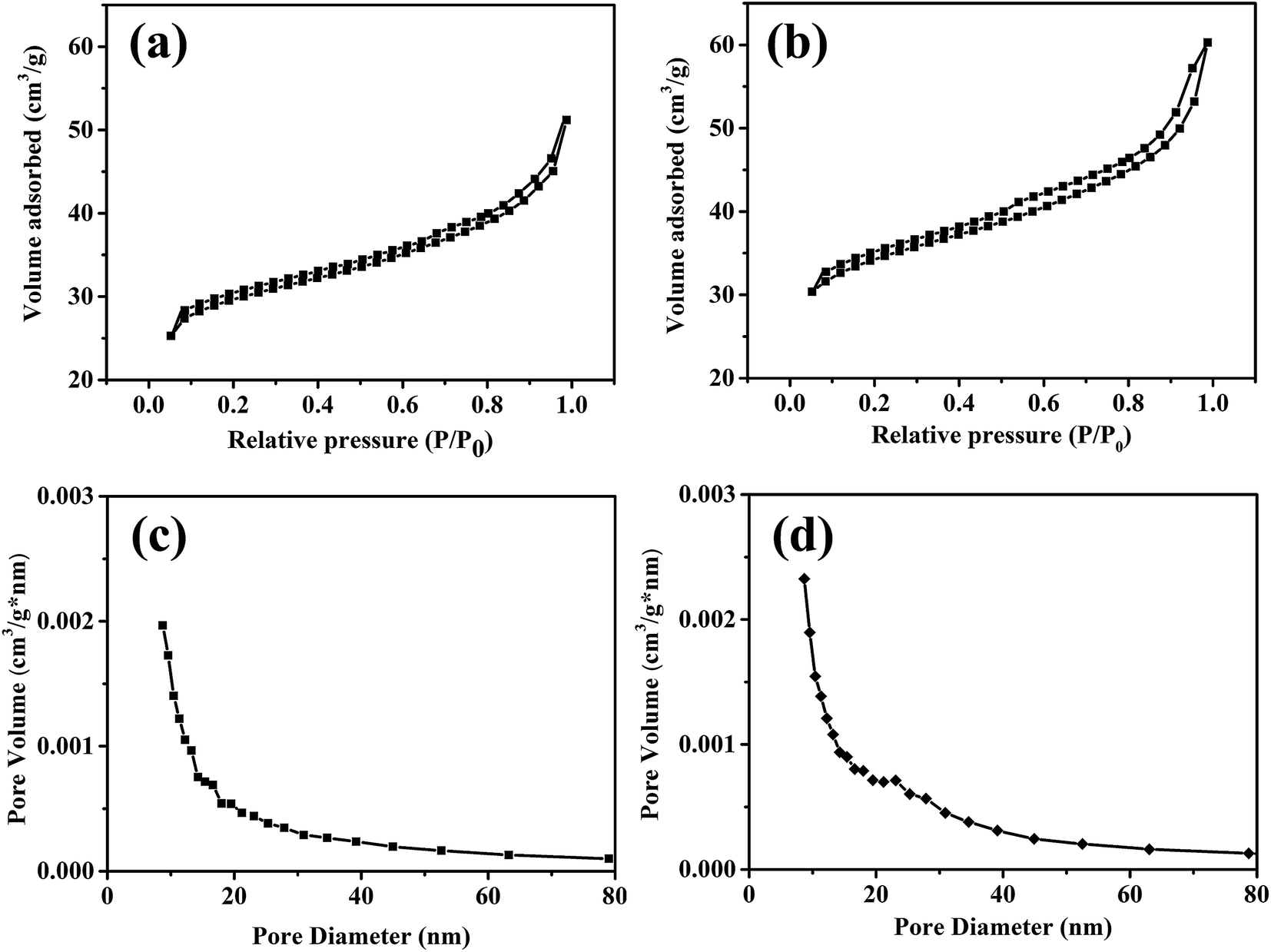 | ||
| Fig. 3 N2 adsorption–desorption isotherms of TC (a) and P-TC (b); the corresponding BJH pore size distribution curves of TC (c) and P-TC (d). | ||
Considering that the plasma may react with the carbon fibers, XPS is employed to investigate the surface compositions and chemical states of TC and P-TC nanofibers. Fig. 4a shows the XPS spectra of Ti 2p. In both samples, two peaks located at around 458.2 and 463.9 eV can be observed, and these two peaks both correspond to Ti4+ in TiO2. No obvious differences are observed in these two spectra, which means that the air plasma treatments do not change the chemical states of Ti. For other three elements, there have been some changes in the spectra, and the details are presented below. The C 1s spectra are shown in Fig. 4b. In the spectra of TC, only one peak appears at 284.8 eV, and it is related to the C–C bonds. However, two extra peaks at around 286 and 288.5 eV appear after the air plasma treatments, which may be corresponding to the C–O–C and O–CO bonds.39 These results imply that during the plasma treatments, the oxygen in the air may have reacted with the carbon fibers, resulting in the generation of new oxygen-containing functional groups, such as C–O and CO. The reaction mechanism was explained by Liu's work that the bombardment of the plasma caused the breaking of some C–C bonds and then generated edge-dangling bonds. Meanwhile, the edge-dangling bonds reacted with oxygen to form oxygen-containing functional groups.36 Wang et al. reported that O-doped architecture of graphite domain can promote the electrical conductivity.40 Similar stories may happen here, the C–O and CO bonds introduced by the plasma treatments may also increase the electrical conductivity. Consistent results can be obtained based on the O 1s spectra shown in Fig. 4c. Before the plasma treatment, a peak at 529.8 eV and a shoulder at 531.4 eV can be observed. The previous peak is related to the Ti–O bond, and it may be assigned to the lattice oxygen. The latter shoulder is ascribed to the formation of oxygen vacancies.41,42 This shoulder may be ascribed to that the crystal sizes of the TiO2 we obtain are too small, and there are many vacancies on the surfaces.32 After the plasma treatments, a peak at 533.1 eV appears in the spectra, and it corresponds to the CO bond. This result also implies that oxygen in the air may have reacted with the carbon during the plasma treatments. The electronegativity of oxygen is very high, and oxygen-containing functional groups attract electrons from the surrounding carbon atoms, resulting in the rearrangement of the surrounding charges. Carbon atoms with positive charge are active sites, thereby enhancing the electrochemical properties of carbon materials. The N 1s spectra for the TC and P-TC samples are shown in Fig. 4d. For TC, a small peak appears at 398.4 eV, which may be related to the pyridine-like N atoms (N-6) from raw material.43 The P-TC spectrum has two peaks at about 399.8 and 401.1 eV. These two peaks are related to the pyrrolic N (N-5) and graphitic N (N-Q).44 All these results indicate that after the plasma treatment, the TiO2 kept unchanged, but new functional groups, edge-dangling bonds and even defects on carbon fibers were introduced, which made the carbon fibers have a better electrical conductivity.
 | ||
| Fig. 4 High-resolution XPS spectra of Ti 2p (a), C 1s (b), O 1s (c) and N 1s (d) of the TC sample and P-TC samples. | ||
In order to understand the microstructures of the nanofibers after plasma treatment, both samples were observed via transmission electron microscopy (TEM). The results of TEM images, high-resolution TEM (HRTEM) images and selected area electron diffraction (SAED) patterns of the two samples are shown in Fig. 5. It can be seen that the surface of P-TC sample (Fig. 5a and b) was obviously rougher than the TC sample (Fig. 5e and f), which infer the surface may have been corroded by the plasma. In both samples, TiO2 nanoparticles piled along the fiber orientation and the diameters of these particles are several nanometers. The lattice fringes in the high-resolution TEM (HRTEM) image (Fig. 5c) has a spacing of 0.35 nm, corresponding to the (101) planes of anatase TiO2. All d-spacings derived from the SAED pattern (Fig. 5d) can be assigned to TiO2. As to the P-TC sample, similar information is obtained (Fig. 5g and h). These results confirmed again that after the plasma treatments, TiO2 in the fibers kept unchanged.
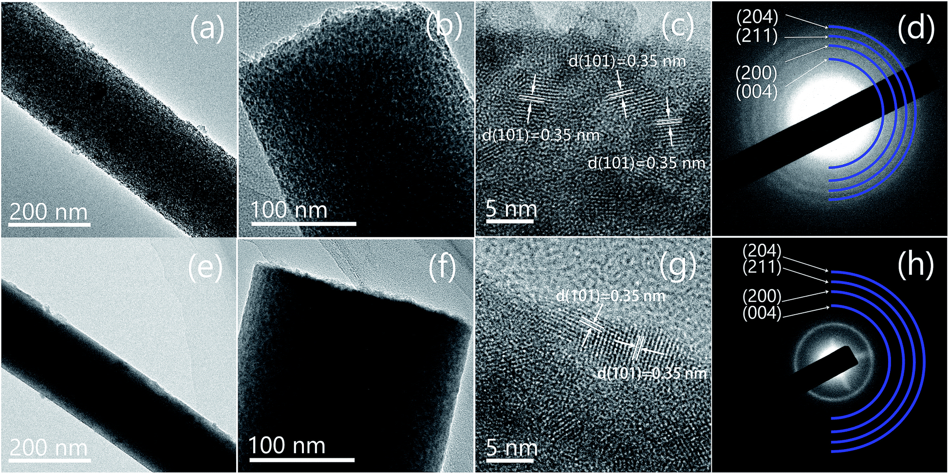 | ||
| Fig. 5 TEM (a and b), HRTEM (c), and SAED result (d) of the P-TC sample; TEM (e and f), HRTEM (g), and SAED result (h) of the TC sample. | ||
The electrochemical performances of two samples were evaluated in sodium half cells. The galvanostatic charge–discharge profiles at 0.2C are shown in Fig. 6. For two samples, the irreversible capacities in the initial cycles result from the formation of solid electrolyte interphase (SEI) and the decomposition of electrolyte. After the first cycle, all the electrodes display sloped charge–discharge profiles without distinct plateaus, suggesting the Na insertion into the TiO2 lattice is homogeneous. The voltage profiles in the second and third cycles overlap for both of electrodes, which demonstrates the insertion and extraction processes are reversible. During 100 cycles, the capacities of TC and P-TC samples are both about 250 mA g−1. According to the TGA results, the TiO2 contents in both samples are larger than 80%, which infers the main capacities of the two samples came from TiO2. Since TiO2 kept unchanged during the plasma treatments, the overall capacities before and after plasma treatments at a low rate of 0.2C kept nearly unchanged. To provide further evidence for the structural stability of the plasma treated TiO2/C nanofibers, SEM images of the P-TC nanofibers were taken from the cycled electrode (shown in Fig. S2†). It can be seen from Fig. S2† that the fibrous morphology of the plasma treated TiO2/C nanofibers remains intact after 3 and 60 cycles. Moreover, there seems to be a thick film in the latter sample, which may be the grown SEI films after 60 cycles. This result indicates a strong tolerance of the material to the volumetric changes during Na+-insertion/extraction cycles.
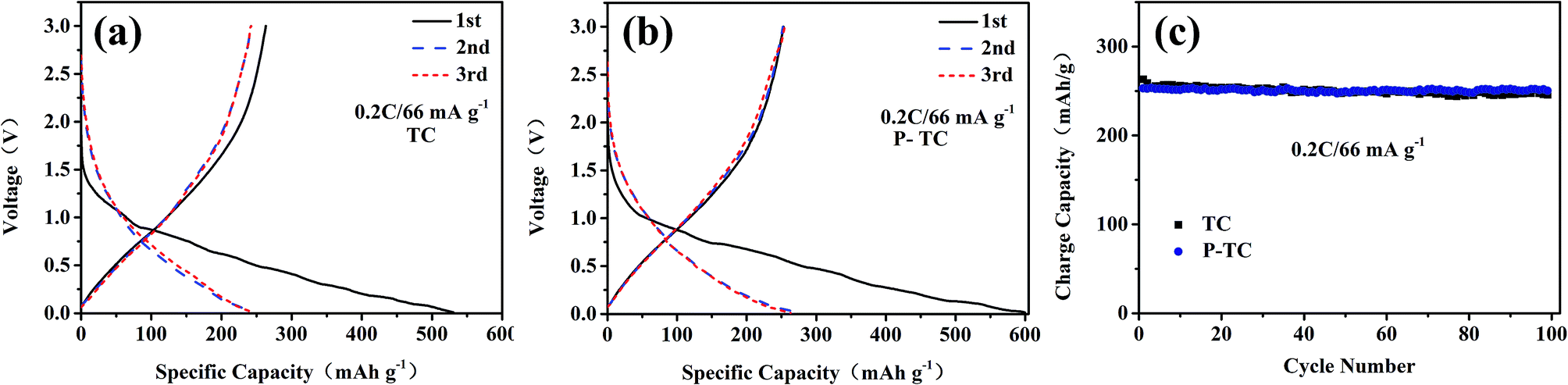 | ||
| Fig. 6 Charge/discharge curves measured at a current of 66 mA g−1 (0.2C) of TC (a) and P-TC (b); cycling performances of the two samples (c). | ||
However, at high current densities, the two samples show distinguished performances. It should be mentioned that all batteries in our work are cycled at 0.5C for 3 cycles before high-rate tests. As displayed in Fig. 7, when the current density is 5C (1650 mA g−1), the capacities for TC and P-TC after 500 cycles are 93 and 204 mA h g−1, respectively. The corresponding capacity retention ratios are 79.9% and 92.8%. In Fig. 7b, when the electrodes are cycled at 10C (3300 mA g−1), the two samples could maintain capacities of 81 and 191 mA h g−1, respectively. The capacity retention ratios after 500 cycles are 85% and 94%. These results show that the plasma treatment greatly improved the rate capability and cycling performance at high rates. The rate performances are demonstrated in Fig. 7c. It can be seen that the P-TC electrode can deliver much larger capacities at high rates. Even at 10C, the reversible capacity of 200 mA h g−1 could be obtained. When the current density goes back to 0.2C, the charge capacity could be maintained at around 260 mA h g−1, which exhibit a superior cycling performance.
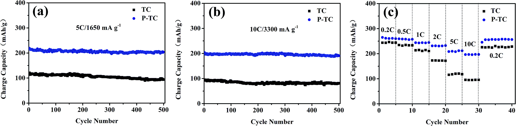 | ||
| Fig. 7 Cycling performances of the two samples at a rate of 5C (a), 10C (b); rate capability at different rates from 0.2C to 10C (c). | ||
In order to understand why the two samples show different rate performances, electrochemical impedance spectroscopy experiments were carried out to study their resistances. For each sample, the data was taken from the same battery cycled after 1st and 50th cycle at a rate of 0.5C. The equivalent circuit for fitting Nyquist plots is shown in the inset picture of Fig. 8a. It can be seen that after the first cycle, the charge transfer resistance of the P-TC sample (169 Ω) is significantly smaller than the TC sample (586 Ω), which means plasma treatment may have increased the electrical conductivity. As discussed above, the surface area of P-TC sample is only 33% larger than TC sample, thus it is inferred that the conductivity of the fibers after plasma treatment is greatly improved. After 50 cycles, the resistance of TC sample increases to 632 Ω. However, the resistance of P-TC becomes smaller, which is 153 Ω. After cycled for 100 cycles, the resistance of P-TC sample is still smaller than the TC sample. These results indicate that the P-TC sample keeps stable during the electrochemical cycles. As discussed above, during the plasma treatments, TiO2 kept unchanged while the C fibers have reacted with the plasma. And the changes of carbon fibers might increase the total electrical conductivity and then decrease the charge transfer resistance of the overall material. However, the detailed mechanism still needs further investigation.
 | ||
| Fig. 8 EIS results of TC (a) and P-TC (b); the inset shows the equivalent circuit used for simulating. | ||
4. Conclusions
In this work, TiO2/C nanofibers are prepared by an electrospinning method, and the air plasma treatments are employed to modify the fibers. Electrochemical results show the rate performances of the samples are greatly improved upon the plasma treatments. Detailed studies indicate that the plasma have reacted with the C fibers and the surface areas are increased. These effects make the samples have a higher electronic conductivity and cyclability during continuous discharge/charge cycles. Our results suggest plasma treatments may be an effective method to modify the carbon based electrode materials and make them present better electrochemical performances.Conflicts of interest
There are no conflicts to declare.Acknowledgements
The project was supported by the National Natural Science Foundation of China (Grant No. 51702294 and 51702295).References
- J. B. Goodenough, Evolution of Strategies for Modern Rechargeable Batteries, Acc. Chem. Res., 2013, 46, 1053–1061 CrossRef CAS PubMed.
- C. X. Zu and H. Li, Thermodynamic analysis on energy densities of batteries, Energy Environ. Sci., 2011, 4, 2614–2624 RSC.
- J. B. Goodenough and K. S. Park, The Li-ion rechargeable battery: a perspective, J. Am. Chem. Soc., 2013, 135, 1167–1176 CrossRef CAS PubMed.
- D. Larcher and J. M. Tarascon, Towards greener and more sustainable batteries for electrical energy storage, Nat. Chem., 2015, 7, 19–29 CrossRef CAS PubMed.
- B. J. Huang, R. Wang, Y. S. Gong, B. B. He and H. W. Wang, Enhanced Cycling Stability of Cation Disordered Rock-Salt Li1.2Ti0.4Mn0.4O2 Material by Surface Modification With Al2O3, Front. Chem., 2019, 7, 107 CrossRef PubMed.
- Y. R. Zhu, Z. D. Huang, Z. L. Hu, L. J. Xi, X. B. Ji and Y. Liu, 3D interconnected ultrathin cobalt selenide nanosheets as cathode materials for hybrid supercapacitors, Electrochim. Acta, 2018, 269, 30–37 CrossRef CAS.
- R. Wang, X. Li, J. Lee, D.-H. Seo, S.-H. Bo, A. Urban and G. Ceder, A disordered rock-salt Li-excess cathode material with high capacity and substantial oxygen redox activity: Li1.25Nb0.25Mn0.5O2, Electrochem. Commun., 2015, 60, 70–73 CrossRef CAS.
- H. Pan, Y. S. Hu and L. Chen, Room-temperature stationary sodium-ion batteries for large-scale electric energy storage, Energy Environ. Sci., 2013, 6, 2338–2360 RSC.
- N. Yabuuchi, K. Kubota, M. Dahbi and S. Komaba, Research Development on Sodium-Ion Batteries, Chem. Rev., 2014, 114, 11636–11682 CrossRef CAS PubMed.
- P. Ge, S. J. Li, K. Y. Zou, X. Gao, X. Y. Cao, G. Q. Zou, H. S. Hou and X. B. Ji, Hierarchical Hollow-Microsphere Metal-Selenide@Carbon Composites with Rational Surface Engineering for Advanced Sodium Storage, Adv. Energy Mater., 2019, 9, 1803035 CrossRef.
- M. X. Deng, S. J. Li, W. W. Hong, Y. L. Jiang, W. Xu, H. L. Shuai, G. Q. Zou, Y. C. Hu, H. S. Hou, W. L. Wang and X. B. Ji, Octahedral Sb2O3 as high-performance anode for lithium and sodium storage, Mater. Chem. Phys., 2019, 223, 46–52 CrossRef CAS.
- H. S. Hou, C. E. Banks, M. J. Jing, Y. Zhang and X. B. Ji, Carbon Quantum Dots and Their Derivative 3D Porous Carbon Frameworks for Sodium-ion Batteries with Ultralong Cycle Life, Adv. Mater., 2015, 27, 7861–7866 CrossRef CAS PubMed.
- J. D. Zhu, C. Chen, Y. Lu, Y. Q. Ge, H. Jiang, K. Fu and X. W. Zhang, Nitrogen-doped carbon nanofibers derived from polyacrylonitrile for use as anode material in sodium-ion batteries, Carbon, 2015, 94, 189–195 CrossRef CAS.
- C. Chen, Y. Lu, Y. Q. Ge, J. D. Zhu, H. Jiang, Y. Q. Li, Y. Hu and X. W. Zhang, Synthesis of nitrogen-doped electrospun carbon nanofibers as anode material for high-performance sodium-ion batteries, Energy Technol., 2016, 4, 1–11 CrossRef.
- Q. Zhao, Y. Huang and X. Hu, A Si/C nanocomposite anode by ball milling for highly reversible sodium storage, Electrochem. Commun., 2016, 70, 8–12 CrossRef CAS.
- D. Wu, Y. Huang and X. Hu, A sulfurization-based oligomeric sodium salt as a high-performance organic anode for sodium ion batteries, Chem. Commun., 2016, 52, 11207–11210 RSC.
- Y. Mei, Y. Huang and X. Hu, Nanostructured Ti-based anode materials for Na-ion batteries, J. Mater. Chem. A, 2016, 4, 12001–12013 RSC.
- S. Wenzel, T. Hara, J. Janek and P. Adelhelm, Room-temperature sodium-ion batteries: improving the rate capability of carbon anode materials by templating strategies, Energy Environ. Sci., 2011, 4, 3342–3345 RSC.
- L. Xiao, Y. Cao, W. A. Henderson, M. L. Sushko, Y. Shao and J. Xiao, et al., Hard carbon nanoparticles as high-capacity, high-stability anodic materials for Na-ion batteries, Nano Energy, 2016, 19, 279–288 CrossRef CAS.
- S. Komaba, W. Murata, T. Ishikawa, N. Yabuuchi, T. Ozeki and T. Nakayama, et al., Electrochemical Na insertion and solid electrolyte interphase for hard-carbon electrodes and application to Na-ion batteries, Adv. Funct. Mater., 2011, 21, 3859–3867 CrossRef CAS.
- L. Wu, X. Hu, J. Qian, F. Pei, F. Wu and R. Mao, et al., Sb–C nanofibers with long cycle life as an anode material for high-performance sodium-ion batteries, Energy Environ. Sci., 2014, 7, 323–328 RSC.
- J. Qian, X. Wu, Y. Cao, X. Ai and H. Yang, High capacity and rate capability of amorphous phosphorus for sodium ion batteries, Angew. Chem., Int. Ed., 2013, 52, 4633–4636 CrossRef CAS PubMed.
- R. Wang, H. X. Mo, S. Li, Y. S. Gong, B. B. He and H. W. Wang, Influence of conductive additives on the stability of red phosphorus-carbon anodes for sodium-ion batteries, Sci. Rep., 2019, 9, 946 CrossRef PubMed.
- X. Zhou, Z. Dai, S. Liu, J. Bao and Y. G. Guo, Ultra-uniform SnOx/carbon nanohybrids toward advanced lithium-ion battery anodes, Adv. Mater., 2014, 26, 3943–3949 CrossRef CAS PubMed.
- Y. Q. Ge, H. Jiang, J. D. Zhu, Y. Lu, C. Chen, Y. Hu, Y. P. Qiu and X. W. Zhang, High cyclability of carbon-coated TiO2 nanoparticles as anode for sodium-ion batteries, Electrochim. Acta, 2015, 157, 142–148 CrossRef CAS.
- Z. Bi, M. P. Paranthaman, P. A. Menchhofer, R. R. Dehoff, C. A. Bridges and M. Chi, et al., Self-organized amorphous TiO2 nanotube arrays on porous Ti foam for rechargeable lithium and sodium ion batteries, J. Power Sources, 2013, 222, 461–466 CrossRef CAS.
- X. Yang, C. Wang, Y. Yang, Y. Zhang, X. Jia and J. Chen, et al., Anatase TiO2 nanocubes for fast and durable sodium ion battery anodes, J. Mater. Chem. A, 2015, 3, 8800–8807 RSC.
- Y. Zhang, X. Pu, Y. Yang, Y. Zhu, H. Hou and M. Jing, et al., An electrochemical investigation of rutile TiO2 microspheres anchored by nanoneedle clusters for sodium storage, Phys. Chem. Chem. Phys., 2015, 17, 15764–15770 RSC.
- Z. Hong, K. Zhou, J. Zhang, Z. Huang and M. Wei, Facile synthesis of rutile TiO2 mesocrystals with enhanced sodium storage properties, J. Mater. Chem. A, 2015, 3, 17412–17416 RSC.
- Y. Xiong, J. Qian, Y. Cao, X. Ai and H. Yang, Electrospun TiO2/C Nanofibers As a High-Capacity and Cycle-Stable Anode for Sodium-Ion Batteries, ACS Appl. Mater. Interfaces, 2016, 8, 16684–16689 CrossRef CAS PubMed.
- Y. Q. Ge, J. D. Zhu, Y. Lu, C. Chen, Y. Hu, Y. P. Qiu and X. W. Zhang, The study on structure and electrochemical sodiation of one-dimensional nanocrystalline TiO2@C nanofiber composites, Electrochim. Acta, 2015, 176, 989–996 CrossRef CAS.
- Y. Wu, X. Liu, Z. Yang, L. Gu and Y. Yu, Nitrogen-Doped Ordered Mesoporous Anatase TiO2 Nanofibers as Anode Materials for High Performance Sodium-Ion Batteries, Small, 2016, 12, 3522–3529 CrossRef CAS PubMed.
- A. Khataee, S. Sajjadi, S. R. Pouran, A. Hasanzadeh and S. W. Joo, A comparative study on electrogeneration of hydrogen peroxide through oxygen reduction over various plasma-treated graphite electrodes, Electrochim. Acta, 2017, 244, 38–46 CrossRef CAS.
- S. M. Chen, D. M. Ren, M. Zhang, H. W. Wang, B. B. He, Y. S. Gong and R. Wang, Improved sodium storage performances of plasma treated self-supported carbon fibers, Solid State Ionics, 2018, 327, 52–58 CrossRef CAS.
- S. Y. Jin, J. Manuel, X. Zhao, W. H. Park and J. H. Ahn, Surface-modified polyethylene separator via oxygen plasma treatment for lithium ion battery, J. Ind. Eng. Chem., 2017, 45, 15–21 CrossRef CAS.
- Z. Liu, Z. Zhao, Y. Wang, S. Dou, D. Yan and D. Liu, et al., In Situ Exfoliated, Edge-Rich, Oxygen-Functionalized Graphene from Carbon Fibers for Oxygen Electrocatalysis, Adv. Mater., 2017, 29, 1606207 CrossRef PubMed.
- X. Lu, W.-L. Yim, B. H. R. Suryanto and C. Zhao, Electrocatalytic Oxygen Evolution at Surface-Oxidized Multiwall Carbon Nanotubes, J. Am. Chem. Soc., 2015, 137, 2901–2907 CrossRef CAS PubMed.
- W. N. W. Salleh and A. F. Ismail, Effect of Stabilization Condition on PEI/PVP-Based Carbon Hollow Fiber Membranes Properties, Sep. Sci. Technol., 2013, 48, 1030–1039 CrossRef CAS.
- B. Parekh, T. Debies, C. M. Evans, B. J. Landi, R. P. Raffaelle and G. A. Takacs, Photo-oxidation of Single-walled Carbon Nanotubes, MRS Proc., 2005, 887, 25–28 Search PubMed.
- T. Wang, S. Shi, Y. Li, M. Zhao, X. Chang and D. Wu, et al., Study of Microstructure Change of Carbon Nanofibers as Binder-Free Anode for High-Performance Lithium-Ion Batteries, ACS Appl. Mater. Interfaces, 2016, 8, 33091–33101 CrossRef CAS PubMed.
- A. Sinhamahapatra, J. P. Jeon and J. S. Yu, A new approach to prepare highly active and stable black titania for visible light-assisted hydrogen production, Energy Environ. Sci., 2015, 8, 3539–3544 RSC.
- W. Fang, Y. Zhou, C. Dong, M. Xing and J. Zhang, Enhanced photocatalytic activities of vacuum activated TiO2 catalysts with Ti3+ and N co-doped, Catal. Today, 2016, 266, 188–196 CrossRef CAS.
- Y. Li, Y. Zhao, H. Cheng, Y. Hu, G. Shi and L. Dai, et al., Nitrogen-Doped Graphene Quantum Dots with Oxygen-Rich Functional Groups, J. Am. Chem. Soc., 2012, 134, 15–18 CrossRef CAS PubMed.
- H. Wang, Y. Zhang, W. Sun, H. T. Tan, J. B. Franklin and Y. Guo, et al., Conversion of uniform graphene oxide/polypyrrole composites into functionalized 3D carbon nanosheet frameworks with superior supercapacitive and sodium-ion storage properties, J. Power Sources, 2016, 307, 17–24 CrossRef CAS.
Footnote |
| † Electronic supplementary information (ESI) available. See DOI: 10.1039/c9ra03224j |
| This journal is © The Royal Society of Chemistry 2019 |