
 Open Access Article
 This Open Access Article is licensed under a Creative Commons Attribution-Non Commercial 3.0 Unported Licence
Preparation of chrome-tanned leather shaving-based hierarchical porous carbon and its capacitance properties
Fei Ma *a,
Shaolan Dinga,
Huijun Renb and
Piaolin Penga
*a,
Shaolan Dinga,
Huijun Renb and
Piaolin Penga
aCollege of Bioresources Chemical and Materials Engineering, Shaanxi University of Science & Technology, Xi'an 710021, China. E-mail: mf3060303201@yeah.net
bSchool of Arts and Sciences of Shaanxi University of Science & Technology, Xi'an 710021, China
First published on 11th June 2019
Abstract
Based on the complexes formed by the original Cr(III) in chrome-tanned leather shavings and the carboxyl groups in collagen as raw materials, a chromium oxide-carbon composite material was formed by the high-temperature carbonization of chromium-tanned leather shavings, followed by the leaching of chrome oxide and activation by KOH. By this method, the hierarchical porous carbon with a high surface area doped with oxygen and nitrogen was prepared. The forming process of the hierarchical porous structure is discussed in detail. Through adjusting the mass ratio of KOH to carbon during the activation process, with a mass ratio of 2, the chromium-tanned leather shavings-based hierarchical porous carbon (called CTSHPC-2) was prepared with an optimal specific surface area (3211 m2 g−1) and a large volume ratio of mesopores to macropores (61.9%) as well as abundant oxygen (13.92 at%) and nitrogen (3.58 at%) functional groups. The results showed that CTSHPC-2 obtained a high specific capacitance of 335.5 F g−1 at a current density of 0.5 A g−1. In addition, it had higher rate performance, low resistance, and better cycle stability. Even when the current density is 10 A g−1 over 5000 cycles, the specific capacity retention rate is 93.5%. Therefore, CTSHPC-2 is a promising electrode material for supercapacitors.
1 Introduction
As alternative energy storage systems, supercapacitors have attracted much attention due to their high power density, fast charging capability and long cycle life. Their performance in experiments depends mainly on their electrode materials.1,2 Therefore, the development of high-performance electrode materials has particular significance.3–5 At present, porous carbon materials are regarded as the most promising electrode materials for supercapacitors on account of their excellent physicochemical stability, high surface area, high porosity and relatively high conductivity.6–8 However, conventional porous carbon usually contains a single type of pore, which makes it is very difficult to exhibit high capacitance and good rate performance simultaneously.6Recently, adopting hierarchical porous carbon (HPC for short) with 3D structures consisting of macropores, mesopores and micropores to fabricate advanced supercapacitors has become an active research topic. This hierarchical porous carbon possesses the advantages of macropores, mesopores and micropores at the same time and shows synergistic effects; thus, it can provide higher capacitance and better rate performance.9–12 However, a template with a special structure is usually used to prepare the hierarchical porous carbon. The preparation of the template is relatively complicated, expensive and time-consuming. This defect limits the commercial application of HPC on a large scale.
In order to simplify the preparation of the templates or to avoid using such templates, scholars have proposed some novel methods for synthesizing hierarchical porous carbon (e.g. co-assembly and self-template methods).13,14 Among these, the self-template method for preparing hierarchical porous carbon has been widely studied using natural biomass materials, such as banana peel, watermelon, hemp, human hair, rice husk, and sakura.15–19 These natural biomass materials exhibit their own porous structures without any artificial synthesis, and the structures of the natural biomass can be chemically converted into hierarchical porous structures.20–24 Furthermore, using the renewable biomass to produce HPC is critical to sustainable development and environmental protection. Although many researchers have prepared HPC from a variety of biomasses, the shortage of raw materials is one of the biggest obstacles to its application. For the extensive application of supercapacitors, developing HPC with low cost and abundant biomass is potentially very beneficial and competitive.25
Leather manufacturing is a traditional process. It is estimated that about 6.5 million tons of leather are globally processed every year.26 During this processing, a large amount of solid waste is generated. Because Cr(III) and collagen fibers form stable complexes during the tanning process, the tanning industry produces large amounts of Cr(III)-containing waste leather shavings. The traditional treatments of these produced Cr(III) leather shavings are mainly landfills and incineration, which waste a great deal of resources and bring out a potential damage to the environment.27 Oliveira prepared chromium oxide-carbon composites with chromium-tanned leather shavings under anaerobic conditions. These composites were used to adsorb and oxidize methylene blue dyes and showed high removal rates.28 However, there are few reports on the preparation of hierarchical porous carbon for supercapacitors using chrome-tanned leather shavings.
The principal component of leather solid waste is collagen, which is rich in C, O and N elements, and Cr(III); due to these characteristics, it is highly advantageous to prepare porous carbon with a high specific surface area doped with oxygen and nitrogen using chrome-tanned leather shavings as a precursor. In this study, using chrome-tanned leather shavings as raw materials, high-temperature carbonization of the chrome-containing leather shavings, dissolution of the chromium oxide template and KOH chemical activation were used to prepare high-surface-area hierarchical porous carbon doped with oxygen and nitrogen. The formation process of the hierarchical porous structure is discussed in detail. The electrochemical properties of the chrome-tanned leather shaving-based hierarchical porous carbon were tested using cyclic voltammetry (CV), galvanostatic charge/discharge (GCD) and electrochemical impedance spectroscopy (EIS) studies. In a three-electrode system with a current of 0.5 A g−1, the highest specific capacitance of the chrome-tanned leather shaving-based porous carbon was 335.5 F g−1, which exhibited better cycle stability simultaneously. Due to these properties, chrome-tanned leather shaving-based hierarchical porous carbon may become a new biomass source of carbonaceous material for high-performance supercapacitors.
2 Experimental
2.1 Materials and reagents
Hydrochloric acid (37 wt%, HCl), potassium hydroxide (KOH), potassium bromate and absolute ethyl alcohol were purchased from Sinopharm Group Chemical Reagent Co., Ltd. (Shanghai, China). Acetylene black, polyvinylidene fluoride (PVDF) and nickel foam were all purchased from Jinghong New Energy Technology Co., Ltd. (Zhengzhou, China). The chrome-tanned leather shavings were donated by a leather company in Jinjiang City, Fujian Province. All chemicals used in the experiments were of analytical grade and were used without any further purification.2.2 Preparation of chrome-tanned leather shaving-based hierarchical porous carbon
In the laboratory, using dry chrome-tanned leather shavings (CTS) as the precursor material, chrome-tanned leather shaving hierarchical porous carbon (CTSHPC) was prepared by pre-carbonization, dissolution of the chromium oxide template and chemical activation. In the process of pre-carbonization, 4 g CTS was heated to 500 °C in a nitrogen-protected tube furnace at a heating rate of 5 °C min−1 and was maintained at 500 °C for 3 h. Then, it was cooled to room temperature to obtain the chromium oxide-carbon composite. The template carbon was obtained by condensing and refluxing for 24 h in 100 ml solution with a mass ratio of 1![[thin space (1/6-em)]](https://www.rsc.org/images/entities/char_2009.gif) :4 of potassium bromate to the chromium oxide-carbon composite. The chromium-containing solution was filtered and recovered to prevent environmental pollution. The template carbon after dissolving in chromium oxide was dried for 12 h at 80 °C. The template carbon and potassium hydroxide were mixed and impregnated in the mass ratios of 1:1, 1:2 and 1:3 for 24 hours, and dried in an oven at 80 °C. Each sample was placed into a corundum ark, placed in a tube furnace, and heated to 800 °C for 1 h to activate it. The heating rate was 5 °C min−1 and the product was naturally cooled to room temperature. Then, it was washed with 2 M hydrochloric acid, deionized water and absolute ethyl alcohol, respectively, dried in an oven at 80 °C, and then ground into powder to complete the preparation of the samples of chrome-tanned leather shaving-based hierarchical porous carbon. The obtained samples were named CTSHPC-x (x represents the impregnation ratio of KOH, where x = 1, 2 or 3). For comparison, the chromium oxide-carbon composite without removing the chromium oxide template after carbonization was impregnated in a KOH mass ratio of 2 for 24 h, then dried and maintained at 800 °C for 1 h. The obtained sample was named chromium-tanned leather shaving-based porous carbon, which was abbreviated as CTSPC-2.
:4 of potassium bromate to the chromium oxide-carbon composite. The chromium-containing solution was filtered and recovered to prevent environmental pollution. The template carbon after dissolving in chromium oxide was dried for 12 h at 80 °C. The template carbon and potassium hydroxide were mixed and impregnated in the mass ratios of 1:1, 1:2 and 1:3 for 24 hours, and dried in an oven at 80 °C. Each sample was placed into a corundum ark, placed in a tube furnace, and heated to 800 °C for 1 h to activate it. The heating rate was 5 °C min−1 and the product was naturally cooled to room temperature. Then, it was washed with 2 M hydrochloric acid, deionized water and absolute ethyl alcohol, respectively, dried in an oven at 80 °C, and then ground into powder to complete the preparation of the samples of chrome-tanned leather shaving-based hierarchical porous carbon. The obtained samples were named CTSHPC-x (x represents the impregnation ratio of KOH, where x = 1, 2 or 3). For comparison, the chromium oxide-carbon composite without removing the chromium oxide template after carbonization was impregnated in a KOH mass ratio of 2 for 24 h, then dried and maintained at 800 °C for 1 h. The obtained sample was named chromium-tanned leather shaving-based porous carbon, which was abbreviated as CTSPC-2.
2.3 Characterization of materials
The microscopic morphologies of the chromium-tanned leather shaving-based porous carbon materials were observed using a scanning electron microscope (SEM, Sirion 200 FEI Netherlands) and a transmission electron microscope (TEM, JEM 2100, JEOL, Japan). The chemical properties of the surfaces of the carbon materials were determined using X-ray photoelectron spectroscopy (XPS, Escalab 250, USA). The crystal structures of the carbon materials were analyzed by X-ray diffraction (XRD, Bruker D8 Advance diffraction) and Raman spectroscopy (LabRAM HR800, Horiba). The porosity of the as-prepared carbon was determined by nitrogen adsorption/desorption measurements (Micromeritics ASAP 2020 system, USA) at about 196 °C. The Brunauer–Emmett–Teller (BET) and Langmuir surface area (SBET) were calculated from the N2 adsorption isotherm data in a relative pressure range of 0.05–0.30. The total pore volume (VTotal) was obtained at p/p0 = 0.995. The microporous (<2 nm) volume (Vmicro), the mesoporous (2 to 50 nm) volume (Vmeso) and the pore size distribution (PSD) were determined using a non-local density functional theory (NLDFT) model by applying slit pores to the N2 adsorption isotherms.2.4 Electrochemical tests
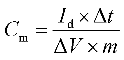
The capacitance properties of the obtained activated carbon materials were evaluated with a three-electrode system. The working electrode was prepared as a uniform mixture with a mass ratio of 80% active material, 10% polyvinylidene fluoride and 10% acetylene black in an agate mortar with dropwise addition of ethanol with stirring. The mixture was pressed on nickel foam (1 cm × 1 cm). The assembled electrodes were finally dried in air at 80 °C for 16 h, and each electrode contained about 2 to 3 mg carbon material.The cyclic voltammetry (CV), electrochemical impedance spectroscopy (EIS) and galvanostatic charge/discharge (GCD) measurements were performed using a CHI 660E electrochemical workstation. A platinum plate (1.5 cm × 1.5 cm) and a saturated calomel electrode were used as the counter electrode and reference electrode, respectively, and KOH aqueous solution (6 M) was used as the electrolyte. The CV measurements were performed in a potential window of −1 V to 0 V with a scan rate range of 10 mV s−1 to 500 mV s−1. At an open circuit voltage, the EIS was measured at a frequency range of 10 kHz to 10 mHz, and the alternating current amplitude was 5 mV. GCD measurements were performed at different current densities from 0.5 A g−1 to 50 A g−1, and the voltage window was 0 to 1 V. The corresponding specific capacitance was calculated as follows:
 | (1) |
3 Results and discussion
3.1 Formation mechanism of the hierarchical porous structure in CTSHPC-x
As shown in Fig. 1, the leather shaving-based 3D porous carbon material was prepared by the direct carbonization of chrome-containing leather shavings, dissolution of the chromium oxide template and chemical activation by KOH.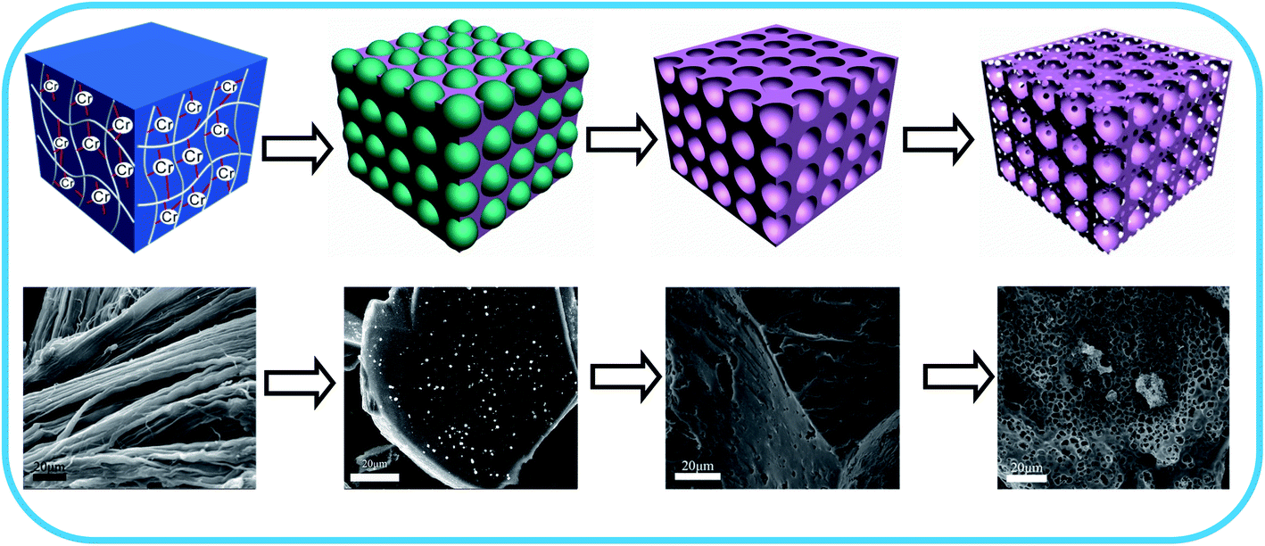 | ||
| Fig. 1 Schematic of the preparation of chromium-tanned leather shaving-based hierarchical porous carbon. | ||
First, because the trivalent chromium ions in the chrome-containing leather shavings are complexed with carboxyl groups on the collagen fibers,29 strong coordinate bonds are formed, and the coordination bond formed by Cr(III) and collagen is shown in Fig. 2.
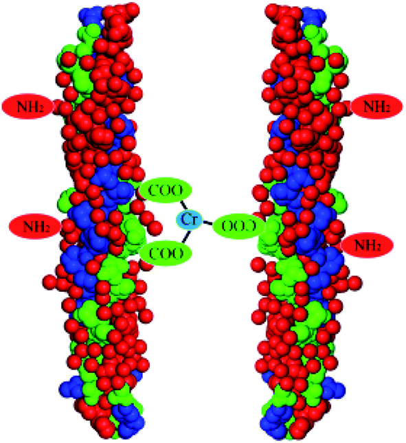 | ||
| Fig. 2 Schematic of the combination of Cr(III) and collagen fibers. | ||
Therefore, in the carbonization process, as the temperature is increased, the volatile substances gradually evaporate to form a chromium oxide-carbon composite, which is consistent with previously reported literature,28 and the size of the chrome oxide ranges from 102 to 824 nm, with an average size of 235 nm. It is believed that the appearance of hierarchical porous structures is related to the removal of chromium oxide. To verify this finding, the template structure of chromium oxide in leather shaving-based carbon was dissolved from the chromium oxide-carbon composite using potassium bromate. The three-dimensional structure of the dissolved chromium oxide is retained in the carbon matrix. Thus, template carbon with 3D structures on its surface is obtained. During the KOH activation, the unique structure of the template carbon is gradually transformed into a hierarchical porous structure (the detailed process is shown in Fig. 1). At the onset of the KOH activation, the active metal potassium is aggregated by interactions on the carbon surface of the chromium-tanned leather shaving base and in the 3D pores after removal of the template. As the activation progresses, the 3D pores in the removed template are enlarged to form macropores, and a large quantity of interconnected micropores and mesopores are formed in these macropores.30,31 When the activation is increased to some extent, the disconnected pores are connected to each other to obtain a hierarchical porous structure. This process can significantly increase the specific surface area and provide efficient electroactive sites for charge regulation, which can greatly increase the charge storage in supercapacitors. The activation mechanism of KOH is reported as follows:32,33
| 6KOH + 2C → 2K + 3H2 + 2K2CO3 | (2) |
| K2CO3 → K2O + CO2 | (3) |
| CO2 + C → 2CO | (4) |
| K2CO3 + 2C → 2K + 3CO | (5) |
| C + K2O → 2K + CO | (6) |
3.2 Morphology and microstructural characterization
The morphologies and structures of the as-prepared hierarchical porous carbon CTSHPC-x materials were observed using scanning electron microscopy (SEM). Fig. 3(a–c) shows SEM images of three CTSHPC-x samples after activation with different KOH masses. It can be clearly seen that all the samples showed porous structures on the surface of the carbon materials due to the presence of the activator; this is because KOH reacts with the carbon matrix to produce numerous pores during the activation process, so the as-prepared activated carbon has a higher specific surface area. However, when the mass ratio of KOH to the template carbon is 2, the carbon material sample has abundant, interconnected and complete mesopores and macropores. When the KOH mass ratio is 3, some of the pore structure of the carbon material is destroyed, as the figure shows. It can be seen that the amount of KOH plays a crucial role in etching the porosity of the carbon material; that is, excess activator may have a negative effect on the pore structure. For contrast, chromium-tanned leather shaving-based porous carbon treated by the conventional KOH activation process is shown in Fig. 3d. From Fig. 3d, it can be seen that the pore structure exhibited by the KOH activation is much less uniform, and the pores are not connected to each other. The template structure of chromium oxide in the chromium oxide-carbon composite material is not sufficient to develop the hierarchical porous structure. | ||
| Fig. 3 SEM images of CTSHPC-1 (a), CTSHPC-2 (b), CTSHPC-3 (c) and CTSPC-2 (d) at the same magnification. | ||
The morphologies and microstructures of the samples were observed by transmission electron microscopy (TEM) at different magnifications. Fig. 4a shows that the sample has a cellular porous network structure. The high resolution TEM micrograph of CTSHPC-2 shows that the predominantly non-uniform mesopores in Fig. 4b enable the preparation of electrodes that are capable of storing large amounts of electrons.34 Fig. 4c also shows that there is a small fraction of the ordered carbon structure in the sample because of the partial graphitization of the carbon-based material due to the KOH etching.35–37 However, the graphitized structure shows good electrical conductivity in the course of rapid charge and discharge and can also enhance ion transport, which is very beneficial for improving the performance of supercapacitors.38
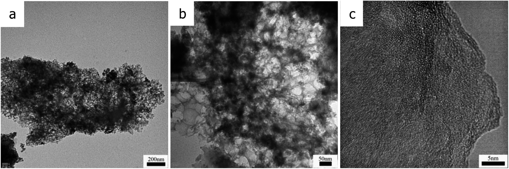 | ||
| Fig. 4 TEM images of CTSHPC-2 (a–c) at different magnifications. | ||
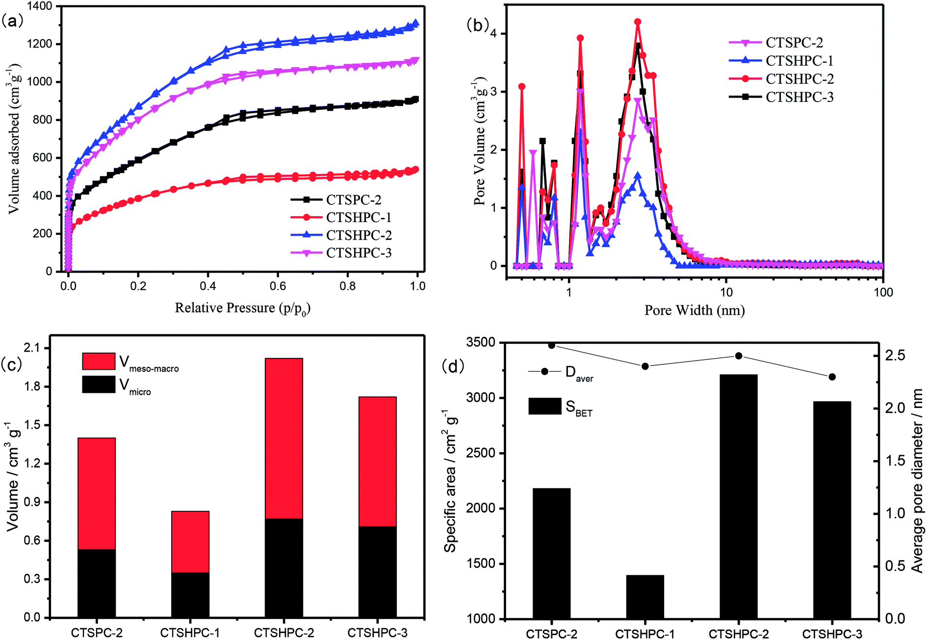
To further determine the pore structures and the specific surface areas of CTSHPC-x, Fig. 5a shows the adsorption/desorption isotherms of the samples in nitrogen (77 K). The 3D porous carbon prepared by the carbonization of chromium-tanned leather shavings and KOH activation in different proportions shows isotherms that are a combination of type I and type IV.39,40 In the area of the relative pressure (p/p0 < 0.05), a sharp increase in the amount of adsorption observed in all the samples indicates that numerous micropores are present. The hysteresis loops with p/p0 = 0.1 to 0.5 and p/p0 = 0.5 to 0.9 indicate the presence of numerous mesopores and some micropores. In the high relative pressure area (p/p0 > 0.9), the observed increases for all the samples indicate that there exists a portion of the macropores. The nitrogen adsorption capacity of CTSHPC-x (x = 1, 2, 3) shows a trend of initial increase, followed by decrease as the KOH proportion is increased; this indicates that excess KOH content may cause collapse of the pore structure during the activation process, resulting in a decrease in the amount of nitrogen adsorption. It can be seen that when the impregnation ratio of KOH is 2, the maximal nitrogen adsorption capacity is obtained. In the comparison between CTSPC-2 and CTSHPC-2, it was found that the nitrogen adsorption capacity of CTSPC-2 containing chromium oxide after carbonization without dissolving the chromium-tanned leather shavings was obviously lower than that of CTSHPC-2 after removing chromium oxide. The reason for this may be that the undissolved chromium oxide occupies the activation sites of KOH.
 | ||
| Fig. 5 (a) N2 adsorption isotherms, (b) pore size distributions, (c) volume ratios of micropores, mesopores and macropores, and (d) average pore sizes and specific surface areas of CTSPC-2 and CTSHPC-x. | ||
The porosities and specific surface area parameters of CTSHPC-x are shown in Fig. 5b–d. The porous characteristics of the samples are listed in Table 1. Obviously, as the mass of KOH is increased, the pore volume and the specific surface area first increase and then decrease. The maximal specific surface area of CTSHPC-2 is 3211 m2 g−1, and the maximal total pore volume is as high as 2.02 cm3 g−1. However, the proportions of the micropore volumes do not apparently change, which are 42.2%, 38.1% and 41.2%, respectively. Interestingly, the proportions of the micropore volumes in the unremoved chromium oxide template CTSPC-2 and the removed chromium oxide template CTSHPC-2 are almost the same, namely 37.8% and 38.1%, respectively. However, there are significant differences between the specific surface areas and the pore volumes. The specific surface area increased from 2182 m2 g−1 to 3211 m2 g−1, and the pore volume increased from 1.40 cm3 g−1 to 2.02 cm3 g−1. This can be attributed to the fact that chromium oxide occupies the activation sites of KOH in CTSPC-2, resulting in a decrease in the specific surface area and the pore volume, while the pore structure and the average pore size are not significantly changed. In summary, the analyses of the pore sizes and structures of the samples confirm that the samples contain pore structures that combine micropores, mesopores and macropores. This structural feature favors the excellent performance of supercapacitors, in which the micropores provide sufficient vacancies for charge accumulation and the mesopores serve as a pathway for shortening the ion diffusion distance, while the macropores can provide memory for buffering the electrolyte ions.
| Sample | SBET (m2 g−1) | SLangmuir (m2 g−1) | Vpore (cm3 g−1) | Vmicro (cm3 g−1) | Vmeso–macro (cm3 g−1) | Daver (nm) |
|---|---|---|---|---|---|---|
| CTSPC-2 | 2182 | 3025 | 1.40 | 0.53 | 0.87 | 2.58 |
| CTSHPC-1 | 1397 | 1959 | 0.83 | 0.35 | 0.48 | 2.38 |
| CTSHPC-2 | 3211 | 4477 | 2.02 | 0.77 | 1.25 | 2.51 |
| CTSHPC-3 | 2968 | 4299 | 1.72 | 0.71 | 1.01 | 2.32 |
Fig. 6a shows the XRD patterns of the chromium-tanned leather shaving-based hierarchical porous carbon samples prepared with different mass ratios of alkali and carbon. From Fig. 6a, it can be seen that the as-prepared activated carbon exhibits a broad (002) crystal plane diffraction peak at 2θ = 15 to 30° and a (100) crystal plane diffraction peak centered at 43°, which indicates that the as-prepared leather shaving-based activated carbon has an amorphous structure.41 The BWLPC-2 peaks at 36° and 64° indicate the presence of a certain proportion of chromium oxide, which is similar to results reported in the literature.28 Moreover, it was found that as the amount of KOH increased, the (002) crystal plane diffraction peak in the leather shaving-based activated carbon gradually weakened until it completely disappeared. This is due to the fact that as the amount of the activator KOH is increased, the etching effect of the activator on the lamellar crystal structure becomes increasingly strong. The K generated in the process of activation is inserted into the graphite crystallites, causing damage to the structure.42
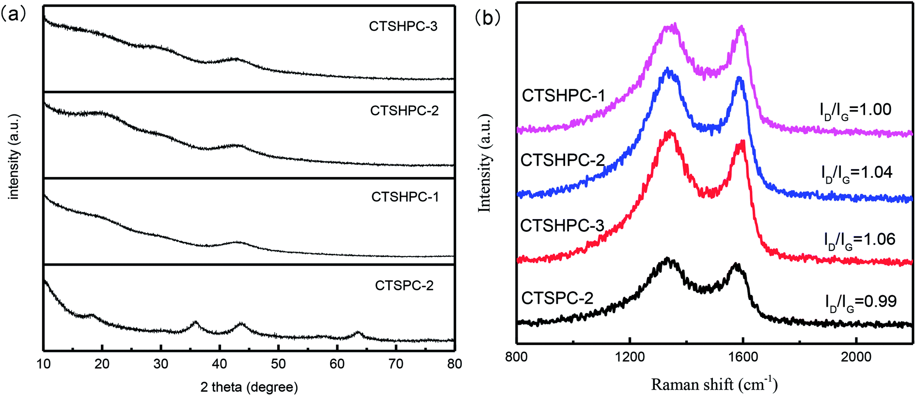 | ||
| Fig. 6 (a) XRD patterns of CTSPC-2 and CTSHPC-x, (b) Raman spectra of CTSPC-2 and CTSHPC-x. | ||
The graphitization structures of the samples were further investigated by Raman spectroscopy. It can be seen from Fig. 6b that there are two characteristic peaks of carbon: (1) the D peak at around 1330 cm−1 represents amorphous carbon with a small grain size; (2) the G peak at around 1590 cm−1 represents crystalline graphite. Moreover, the relative intensity ratio (ID/IG) of the two bands is in direct proportion to the amount of defect sites in the graphite carbon.43,44 The lower the ratio, the higher the graphitization. As the KOH ratio increases from 1 to 3, the ID/IG value increases from 1 of CTSHPC-1 to 1.06 of CTSHPC-3, demonstrating amorphous properties and a low degree of graphitization. In contrast, the ID/IG value of CTSPC-2 is 0.99, which is lower than that of the chromium-free activated sample. This is because the presence of chromium oxide prevents K from destroying the graphitized structure.
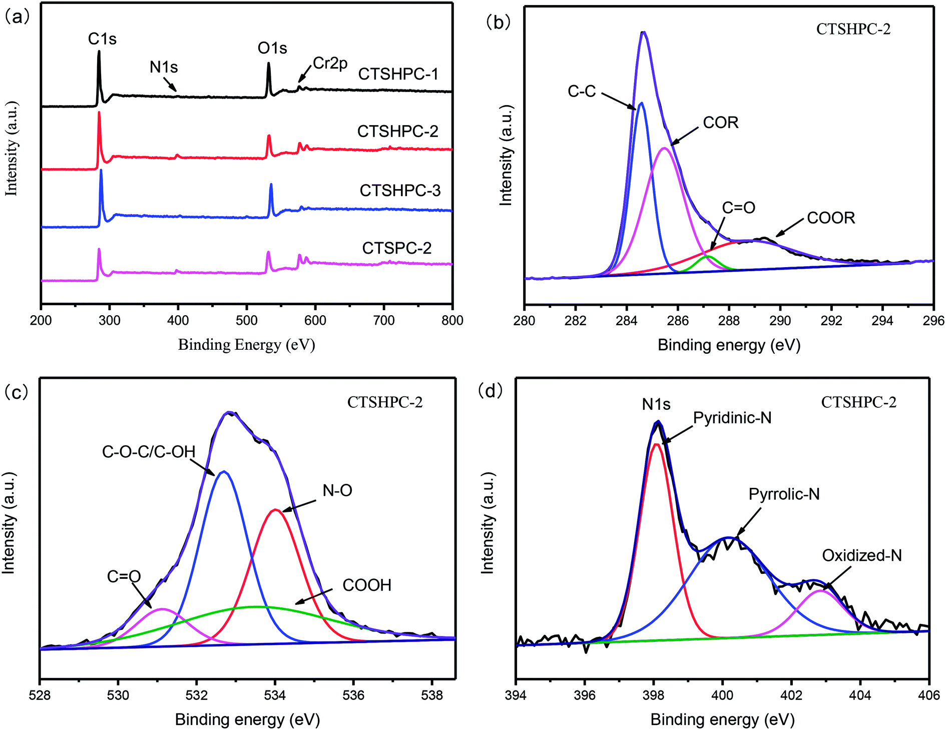
The chemical properties of the carbon surfaces were determined by XPS studies. The XPS spectra of CTSHPC-x are shown in Fig. 7a, which indicates that there are four elements of C, O, N and Cr on the surface of CTSHPC-x. The content ratio of each element is listed in Table 2. Because the main component of leather shavings is protein, it is reasonable that the leather shaving-based porous carbon contains O and N elements. The nitrogen content decreases significantly with increasing amount of KOH. When the mass ratio is 2:1, the nitrogen content of CTSHPC-2 (3.58 at%) is the highest, and the nitrogen content is decreased. The reason for this is that KOH activation may result in the loss of doped nitrogen content, which is similar to the reported literature.45–49 In order to further determine the surface chemical composition of CTSHPC-2 carbon material, the C1s, O1s, and N1s spectra of the samples were carefully analyzed by the peak fitting method, as shown in Fig. 7b–d. The C1s of CTSHPC-2 was fitted into four peaks (Fig. 7b), which correspond to the aliphatic carbon at 284.4 eV (C–C), the hydroxyl and phenolic groups at 285.9 eV (COR), the ketone and quinone groups at 287.6 eV (C![[double bond, length as m-dash]](https://www.rsc.org/images/entities/char_e001.gif) O), and carboxyl groups at 289.1 eV (COOR).50
O), and carboxyl groups at 289.1 eV (COOR).50
 | ||
| Fig. 7 (a) XPS spectra of CTSPC-2 and CTSHPC-x, (b) C1s peak fitting of the XPS spectrum of CTSPC-2, (c) O1s peak fitting of the XPS spectrum of CTSHPC-2, (d) N1s peak fitting of the XPS spectrum of CTSHPC-2. | ||
| Sample | O/at% | C/at% | N/at% | Cr/at% |
|---|---|---|---|---|
| CTSPC-2 | 19.28 | 71.38 | 4.42 | 4.92 |
| CTSHPC-1 | 17.90 | 80.48 | 1.11 | 0.52 |
| CTSHPC-2 | 13.92 | 81.67 | 3.58 | 0.83 |
| CTSHPC-3 | 16.69 | 81.85 | 1.10 | 0.36 |
The four characteristic peaks of O1s (Fig. 6c) are concentrated at 531.5 eV, 532.4 eV, 533.3 eV and 534.2 eV, respectively.51,52 These peaks are attributed to the CO group (the 1st), the carbonyl oxygen atom in the ester, the amide in the hydroxyl or ether, the anhydride and the carbonyl oxygen atom (the 2nd), the ether oxygen atom in the ester and anhydride (the 3rd) and the atoms in the oxygen carboxyl group (the 4th).46,47
Similarly, the co-existence of pyridine nitrogen (398.3 eV), pyrrole/pyridone-N (400.2 eV) and pyridine-N-oxygen (402.7 eV) in CTSHPC-2 is demonstrated in the N1s spectrum (Fig. 7d).48 It has been reported that both pyridine nitrogen and pyrrole/pyridone-N have high chemical activity and can reversibly bind with electrolyte ions to increase charge storage. The pyridine-N-oxygen (402.7 eV) may play an important role in enhancing the electron transfer.53,54
3.3 Electrochemical characterization
In order to verify the electrochemical performance of the leather shaving-based porous carbon as a supercapacitor electrode material, CV, GCD and EIS were measured using a three-electrode system in 6 mol KOH aqueous solution. Fig. 8a shows the CV curves of all the samples at different scan rates in a potential window of −1 to 0 V. It can be observed that all the curves show approximately rectangular shapes, which indicates double-layer capacitance behavior. A voltage hump occurs from −0.4 V to 0 V, which can be attributed to a redox reaction of an oxygen- or nitrogen-containing functional group on the surface of the porous carbon.55–57 In addition, the CV curve area of CTSHPC-(1–3) tends to increase first and then decrease; the CV curve area of CTSHPC-2 is the largest, which indicates that it has the highest capacitance. The increased specific capacitance may arise from the increased contents of nitrogen and oxygen functional groups and the increased specific surface area of the porous carbon material. It is reported that changes in the specific surface area and amounts of nitrogen and oxygen functional groups are determined by the quality of the KOH activator, which indicates that selecting an appropriate amount of KOH activator is very beneficial to improve the capacitance. In contrast, the CV curve of CTSHPC-2 is greater than that of CTSPC-2. | ||
| Fig. 8 Electrochemical performance of CTSPC-2 and CTSHPC-x in a three-electrode system: (a) CV curves of CTSPC-2 and CTSHPC-x at 100 mV s−1; (b) GCD curves of CTSPC-2 and CTSHPC-x at 1 A g−1; (c) CV curves of CTSHPC-2 at various scan rates; (d) GCD curves of CTSHPC-2 at various current densities; (e) Nyquist diagrams of CTSPC-2 and CTSHPC-x; (f) specific capacitances of CTSPC-2 and CTSHPC-x at 0.2 to 20 A g−1; (g) cycle stability test of CTSHPC-2 at 10 A g−1. | ||
Fig. 8b shows the GCD curves of CTSHPC-x at the current density of 1 A g−1. The specific capacitance of each electrode material was calculated according to the discharge curves of the supercapacitor using eqn (2). The specific capacitances of CTSPC-2 and CTSHPC-x (x = 1 to 3) are 193.4, 180.2, 318.4, and 249.1 F g−1, respectively. It is worth noting that CTSHPC-2 obviously shows a longer discharge time than the other samples, which is consistent with the CV results in Fig. 8a; this arises primarily because CTSHPC-2 contains oxygen and nitrogen groups and unique 3D hierarchical network structures, which can create larger accessible areas and suitable ion/electron transport paths.
Fig. 8c further shows the CV curves of CTSHPC-2 at scan rates of 5 mV s−1 to 500 mV s−1. As shown in Fig. 8c, all the CV curves of CTSHPC-2 are similar rectangles without any apparent distortion, even at the high scan rate of 500 mV s−1. This can be attributed to the porous hierarchical carbon structure and good wettability derived from CTSHPC-2, which facilitate electrolyte migration through the electrodes. Furthermore, these changes are basically due to insufficient storage time for the migration and accumulation of ions in the porous material at higher scanning rates; the decrease of the surface area of the electrolyte ions in contact with the carbon material leads to the formation of poor electric double-layer capacitance.
The GCD curves of CTSHPC-2 electrodes at different current densities are shown in Fig. 8d. The approximately symmetric GCD curves confirm that the reversible charge–discharge process is consistent with the abovementioned CV results, which is characteristic of an ideal capacitor. As shown in Fig. 8d, the capacitance of CTSHPC-2 was calculated to be as high as 335.5 F g−1 at 0.5 A g−1. This capacitance is evidently higher than those of previously reported porous carbons, including three-dimensional interconnected nitrogen-doped mesoporous carbon (178.5 F g−1 at 0.5 A g−1)58 and biomass-derived nitrogen-doped carbon (243.2 F g−1 at 0.5 A g−1).59 Moreover, at a current density of 50 A g−1, CTSHPC-2 still exhibits a relatively high specific capacitance of 213 F g−1. It can be seen that the specific capacitance decreased as the current density increased, because the large current density limits the diffusion of ions, according to reports.
The specific capacitances of the samples at current densities of 0.5 to 50 A g−1 were analyzed by galvanostatic charge–discharge studies. Fig. 8e shows the relationship between the specific capacitance of the electrode and the current density. As the current density increases, the retention rates of the samples are 72%, 67%, 70%, and 68%, respectively; the CTSPC-2 sample has the highest capacitance retention. This phenomenon can be explained by the ratios of the mesopores to the macropores in CTSPC-2 (62.2%), CTSHPC-1 (57.8%), CTSHPC-2 (61.9%) and CTSHPC-3 (58.8%). Among them, the ratio of the mesopores to the macropores of CTSHPC-2 is the largest, which makes it possible rapidly help electrolyte ions enter the active layer in the electrode matrix at higher current densities.
To further investigate the capacitive behavior of CTSPC-2 and CTSHPC-x, EIS was used to evaluate the charge transport and ion diffusion properties. The electrochemical impedance spectra of the electrode materials are shown in Fig. 8f, all of which are similar and contain three areas: a semicircle in the high frequency region, a straight line with a slope of 45° in the low frequency region and a straight line with a slope greater than 45° in the very low frequency region. The intercept on the X-axis refers to the solution resistance (Rs), which includes the basic resistance of the material, the electrical resistance of the electrolyte solution, and the contact resistance at the interface between the active porous material and the current collector. The charge transfer resistance (Rct) is expressed by the diameter of the semicircle on the X-axis in the low frequency region.60,61 As can be seen from the Nyquist diagram, the intercepts of the Z0 axis are in the following order: CTSPC-2 (0.128) > CTSHPC-3 (0.114) > CTSHPC-1 (0.098) > CTSHPC-2 (0.083). Meanwhile, the diameter of the semicircle of CTSHPC-2 is much smaller than that of the other semicircles, which indicates that the charge transfer resistance is smaller but the specific capacitance is higher. This is consistent with the results of the CV and GCD analyses.
For practical applications of electrochemical supercapacitors, cycle stability is a key factor. The cycle performance of the CTSHPC-2 electrode was evaluated at 10 A g−1, as shown in Fig. 8g. About 93.5% of the capacitance retention was retained after 5000 charge–discharge cycles, indicating that the CTSHPC-2 electrode possesses excellent cycle stability and good rate capability. The insets in Fig. 8g show the first three cycles and the last three cycles of the durability test curves. Obviously, the shapes of the last three cycles changed little; only the voltage drop slightly increased. According to the previous reports, this may be due to aging of the adhesive in the electrode. All the electrochemical results indicate that CTSHPC-2 is a potential candidate for supercapacitor electrode materials due to its high specific capacitance, good rate performance and cycle stability.
4 Conclusion
In this study, oxygen–nitrogen-doped hierarchical porous carbon prepared from chromium-tanned leather shavings was developed by carbonization, leaching of the chromium oxide templates by potassium bromate and KOH activation. The chromium oxide-carbon composite material was prepared by high-temperature carbonization of chromium-tanned leather shavings, and the template carbon with a 3D structure was obtained by removing the chromium oxide. During the KOH activation, the unique structure of the template carbon gradually transformed into a hierarchical porous structure with micropores, mesopores and macropores. In addition, some oxygen and nitrogen impurity functional groups were retained on the surface of CTSHPC-2. Due to its unique combination of hierarchical pores and oxygen–nitrogen-doping, CTSHPC-2 possesses high specific capacitance, good rate performance, low resistance and excellent cycle stability. Especially, CTSHPC-2 obtains a high specific capacitance of 335.5 F g−1 at 0.5 A g−1. Even at a current density of 10 A g−1, the specific capacitance remains at 247 F g−1 after 5000 cycles, and the retention rate is 93.5%. These optimal results further prove that CTSHPC-2 can be regarded as a potential electrode material for high-performance supercapacitors.Conflicts of interest
There are no conflicts to declare.References
- J. Wang, P. Nie, B. Ding, S. Dong, X. Hao, H. Dou and X. Zhang, J. Mater. Chem. A, 2017, 5, 2411–2428 RSC.
- A. Borenstein, O. Hanna, R. Attias, S. Luski, T. Brousse and D. Aurbach, J. Mater. Chem. A, 2017, 5, 12653–12672 RSC.
- V. Augustyn, P. Simon and B. Dunn, Energy Environ. Sci., 2014, 7, 1597 RSC.
- N. Nitta, F. Wu, J. T. Lee and G. Yushin, Mater. Today, 2015, 18, 252–264 CrossRef CAS.
- H.-J. Peng, J.-Q. Huang, X.-B. Cheng and Q. Zhang, Adv. Energy Mater., 2017, 7, 1700260 CrossRef.
- L. L. Zhang and X. S. Zhao, Chem. Soc. Rev., 2009, 38, 2520–2531 RSC.
- C. Liu, Z. Yu, D. Neff, A. Zhamu and B. Z. Jang, Nano Lett., 2010, 10, 4863–4868 CrossRef CAS PubMed.
- E. Frackowiak, Phys. Chem. Chem. Phys., 2007, 9, 1774–1785 RSC.
- D. S. Su and R. Schlogl, ChemSusChem, 2010, 3, 136–168 CrossRef CAS PubMed.
- G. Hong, S. Diao, A. L. Antaris and H. Dai, Chem. Rev., 2015, 115, 10816–10906 CrossRef CAS PubMed.
- W. Yang, W. Yang, L. Kong, A. Song, X. Qin and G. Shao, Carbon, 2018, 127, 557–567 CrossRef CAS.
- Y. Shao, M. F. El-Kady, C. W. Lin, G. Zhu, K. L. Marsh, J. Y. Hwang, Q. Zhang, Y. Li, H. Wang and R. B. Kaner, Adv. Mater., 2016, 28, 6719–6726 CrossRef CAS PubMed.
- P. K. Tripathi, M. Liu, Y. Zhao, X. Ma, L. Gan, O. Noonan and C. Yu, J. Mater. Chem. A, 2014, 2, 8534 RSC.
- M. Li, C. Liu, H. Cao, H. Zhao, Y. Zhang and Z. Fan, J. Mater. Chem. A, 2014, 2, 14844 RSC.
- Y. Lv, L. Gan, M. Liu, W. Xiong, Z. Xu, D. Zhu and D. S. Wright, J. Power Sources, 2012, 209, 152–157 CrossRef CAS.
- L.-F. Chen, Z.-H. Huang, H.-W. Liang, W.-T. Yao, Z.-Y. Yu and S.-H. Yu, Energy Environ. Sci., 2013, 6, 3331 RSC.
- W. Chen, H. Zhang, Y. Huang and W. Wang, J. Mater. Chem., 2010, 20, 4773 RSC.
- W. Qian, F. Sun, Y. Xu, L. Qiu, C. Liu, S. Wang and F. Yan, Energy Environ. Sci., 2014, 7, 379–386 RSC.
- F. Ma, S. Ding, H. Ren and Y. Liu, RSC Adv., 2019, 9, 2474–2483 RSC.
- H. Jiang, P. S. Lee and C. Li, Energy Environ. Sci., 2013, 6, 41–53 RSC.
- C. Zhang, X. Zhu, M. Cao, M. Li, N. Li, L. Lai, J. Zhu and D. Wei, ChemSusChem, 2016, 9, 932–937 CrossRef CAS PubMed.
- R. Thangavel, K. Kaliyappan, H. V. Ramasamy, X. Sun and Y. S. Lee, ChemSusChem, 2017, 10, 2805–2815 CrossRef CAS PubMed.
- J. Niu, R. Shao, J. Liang, M. Dou, Z. Li, Y. Huang and F. Wang, Nano Energy, 2017, 36, 322–330 CrossRef CAS.
- C. Chen, Y. Zhang, Y. Li, J. Dai, J. Song, Y. Yao, Y. Gong, I. Kierzewski, J. Xie and L. Hu, Energy Environ. Sci., 2017, 10, 538–545 RSC.
- D. Liu, W. Zhang, H. Lin, Y. Li, H. Lu and Y. Wang, RSC Adv., 2015, 5, 19294–19300 RSC.
- J. Kanagaraj, T. Senthilvelan, R. C. Panda and S. Kavitha, J. Cleaner Prod., 2015, 89, 1–17 CrossRef CAS.
- I. C. Kantarli and J. Yanik, J. Hazard. Mater., 2010, 179, 348–356 CrossRef CAS PubMed.
- L. C. Oliveira, C. V. Coura, I. R. Guimaraes and M. Goncalves, J. Hazard. Mater., 2011, 192, 1094–1099 CrossRef CAS PubMed.
- G. Liu, G. Haiqi, K. Li, J. Xiang, T. Lan and Z. Zhang, J. Colloid Interface Sci., 2018, 514, 338–348 CrossRef CAS PubMed.
- Z. Zheng, Q. Gao and J. Jiang, Carbon, 2010, 48, 2968–2973 CrossRef CAS.
- Q. Zhao, X. Wang, H. Xia, J. Liu, H. Wang, J. Gao, Y. Zhang, J. Liu, H. Zhou, X. Li, S. Zhang and X. Wang, Electrochim. Acta, 2015, 173, 566–574 CrossRef CAS.
- J. Zhou, Z. Li, W. Xing, H. Shen, X. Bi, T. Zhu, Z. Qiu and S. Zhuo, Adv. Funct. Mater., 2016, 26, 7945 CrossRef CAS.
- R. Satish, A. Vanchiappan, C. L. Wong, K. W. Ng and M. Srinivasan, Electrochim. Acta, 2015, 182, 474–481 CrossRef CAS.
- K. Qin, E. Liu, J. Li, J. Kang, C. Shi, C. He, F. He and N. Zhao, Adv. Energy Mater., 2016, 6, 1600755 CrossRef.
- Y. Zhou, J. Ren, L. Xia, H. Wu, F. Xie, Q. Zheng, C. Xu and D. Lin, ChemElectroChem, 2017, 4, 3181–3187 CrossRef CAS.
- X. Wu, L. Jiang, C. Long and Z. Fan, Nano Energy, 2015, 13, 527–536 CrossRef CAS.
- J. Zhao, Y. Li, G. Wang, T. Wei, Z. Liu, K. Cheng, K. Ye, K. Zhu, D. Cao and Z. Fan, J. Mater. Chem. A, 2017, 5, 23085–23093 RSC.
- X. Tian, H. Ma, Z. Li, S. Yan, L. Ma, F. Yu, G. Wang, X. Guo, Y. Ma and C. Wong, J. Power Sources, 2017, 359, 88–96 CrossRef CAS.
- H. Wu, Y. Deng, J. Mou, Q. Zheng, F. Xie, E. Long, C. Xu and D. Lin, Electrochim. Acta, 2017, 242, 146–158 CrossRef CAS.
- S. Chen, J. Duan, M. Jaroniec and S. Z. Qiao, J. Mater. Chem. A, 2013, 1, 9409 RSC.
- J. Hou, K. Jiang, R. Wei, M. Tahir, X. Wu, M. Shen, X. Wang and C. Cao, ACS Appl. Mater. Interfaces, 2017, 9, 30626–30634 CrossRef CAS PubMed.
- K. Wang, N. Zhao, S. Lei, R. Yan, X. Tian, J. Wang, Y. Song, D. Xu, Q. Guo and L. Liu, Electrochim. Acta, 2015, 166, 1–11 CrossRef CAS.
- M. Liu, L. Gan, W. Xiong, Z. Xu, D. Zhu and L. Chen, J. Mater. Chem. A, 2014, 2, 2555–2562 RSC.
- M. Liu, L. Gan, W. Xiong, F. Zhao, X. Fan, D. Zhu, Z. Xu, Z. Hao and L. Chen, Energy Fuels, 2013, 27, 1168–1173 CrossRef CAS.
- R. Xing, T. Zhou, Y. Zhou, R. Ma, Q. Liu, J. Luo and J. Wang, Nano-Micro Lett., 2018, 10, 3 CrossRef PubMed.
- D. Gu, Y. Zhou, R. Ma, F. Wang, Q. Liu and J. Wang, Nano-Micro Lett., 2018, 10, 29 CrossRef PubMed.
- D. Guo, S. Han, R. Ma, Y. Zhou, Q. Liu, J. Wang and Y. Zhu, Microporous Mesoporous Mater., 2018, 270, 1–9 CrossRef CAS.
- T. Zhou, R. Ma, Y. Zhou, R. Xing, Q. Liu, Y. Zhu and J. Wang, Microporous Mesoporous Mater., 2018, 261, 88–97 CrossRef CAS.
- T. Zhou, Y. Zhou, R. Ma, Z. Zhou, G. Liu, Q. Liu, Y. Zhu and J. Wang, Carbon, 2017, 114, 177–186 CrossRef CAS.
- Y. Shu, J. Maruyama, S. Iwasaki, S. Maruyama, Y. Shen and H. Uyama, J. Power Sources, 2017, 364, 374–382 CrossRef CAS.
- H. Zhu, J. Yin, X. Wang, H. Wang and X. Yang, Adv. Funct. Mater., 2013, 23, 1305–1312 CrossRef CAS.
- D. Hulicova-Jurcakova, M. Seredych, G. Q. Lu and T. J. Bandosz, Adv. Funct. Mater., 2009, 19, 438–447 CrossRef CAS.
- Y. Deng, Y. Xie, K. Zou and X. Ji, J. Mater. Chem. A, 2016, 4, 1144–1173 RSC.
- J. Ding, Z. Li, K. Cui, S. Boyer, D. Karpuzov and D. Mitlin, Nano Energy, 2016, 23, 129–137 CrossRef CAS.
- V. Datsyuk, M. Kalyva, K. Papagelis, J. Parthenios, D. Tasis, A. Siokou, I. Kallitsis and C. Galiotis, Carbon, 2008, 46, 833–840 CrossRef CAS.
- X. Wei, S. Wan and S. Gao, Nano Energy, 2016, 28, 206–215 CrossRef CAS.
- P. Ramakrishnan and S. Shanmugam, Electrochim. Acta, 2014, 125, 232–240 CrossRef CAS.
- G. Lin, R. Ma, Y. Zhou, C. Hu, M. Yang, Q. Liu, S. Kaskel and J. Wang, J. Colloid Interface Sci., 2018, 527, 230–240 CrossRef CAS PubMed.
- G. Lin, R. Ma, Y. Zhou, Q. Liu, X. Dong and J. Wang, Electrochim. Acta, 2018, 261, 49–57 CrossRef CAS.
- P. Cheng, S. Gao, P. Zang, X. Yang, Y. Bai, H. Xu, Z. Liu and Z. Lei, Carbon, 2015, 93, 315–324 CrossRef CAS.
- L. Zhi, T. Li, H. Yu, S. Chen, L. Dang, H. Xu, F. Shi, Z. Liu and Z. Lei, Carbon, 2017, 113, 100–107 CrossRef CAS.
| This journal is © The Royal Society of Chemistry 2019 |