 Open Access Article
Fabrication of plasmonic dye-sensitized solar cells using ion-implanted photoanodes†
Navdeep Kaura,
Aman Mahajan *a,
Viplove Bhullara,
Davinder Paul Singha,
Vibha Saxenab,
A. K. Debnathb,
D. K. Aswalc,
Devarani Devid,
Fouran Singhd and
Sundeep Choprad
aDepartment of Physics, Guru Nanak Dev University, Amritsar – 143 005, India. E-mail: aman.phy@gndu.ac.in
bThin Film Devices Section, Technical Physics Division, Bhabha Atomic Research Centre, Mumbai – 400 085, India
cNational Physical Laboratory, New Delhi – 110012, India
dInter University Accelerator Centre, New Delhi – 110 0067, India
First published on 1st July 2019
Abstract
Plasmonic dye-sensitized solar cells containing metal nanoparticles suffer from stability issues due to their miscibility with liquid iodine-based electrolytes. To resolve the stability issue, herein, an ion implantation technique was explored to implant metal nanoparticles inside TiO2, which protected these nanoparticles with a thin coverage of TiO2 melt and maintained the localized surface plasmon resonance oscillations of the metal nanoparticles to efficiently enhance their light absorption and make them corrosion resistant. Herein, Au nanoparticles were implanted into the TiO2 matrix up to the penetration depth of 22 nm, and their influence on the structural and optical properties of TiO2 was studied. Moreover, plasmonic dye-sensitized solar cells were fabricated using N719 dye-loaded Au-implanted TiO2 photoanodes, and their power conversion efficiency was found to be 44.7% higher than that of the unimplanted TiO2-based dye-sensitized solar cells due to the enhanced light absorption of the dye molecules in the vicinity of the localized surface plasmon resonance of Au as well as the efficient electron charge transport at the TiO2@Au@N719/electrolyte interface.
1. Introduction
Localized surface plasmon resonance (LSPR), a unique characteristic of metal nanoparticles (Mnps) that arises due to the collective oscillations of free electrons in metals and their surrounding dielectric medium, has been extensively investigated in various applications such as in photocatalysis,1,2 electrochemistry,3,4 photovoltaics,5,6 water-splitting,7,8 light-emitting diodes,9,10 sensing,11,12 and plasmofluidics.13,14 In photovoltaic devices, the plasmonic Mnps induce a stronger near-field coupling at the Mnps and semiconductor interface upon interaction with the incident light. This leads to a Mie-type forward light scattering and hence enhances the light absorption to improve the power conversion efficiency (PCE) of these devices.15,16In recent years, among different photovoltaic devices, dye-sensitized solar cells (DSSCs) have gained significant attention due to their low fabrication cost, eco-friendliness and good photovoltaic performance even under indirect light illumination.17 The LSPR of Mnps has been explored in DSSCs to further enhance their PCE by improving light absorption along with fast electron charge transfer from the dye molecules to TiO2![[thin space (1/6-em)]](https://www.rsc.org/images/entities/char_2009.gif) 18–20 and inhibiting the back recombination of electrons from either the dye molecules or the conduction band (C.B.) of TiO2 to the electrolyte.21,22 Chen et al.23 optimized TiO2-based DSSCs incorporated with 0.8 wt% of Au nps (200–300 nm size) and showed a 12.2% increase in the PCE as compared to the case of TiO2-based DSSCs due to enhanced light absorption induced by the Au nps. Muduli et al.24 reported a 16% increase in the PCE of TiO2–Au-based DSSCs owing to fast electron transport and reduced recombination of electrons and holes at the TiO2@Au/dye/electrolyte interface. Chander et al.25 showed an increment of 19.12% in the PCE of TiO2-based DSSCs loaded with 0.24 wt% Au nps (36 nm size). Zhao et al.26 demonstrated that the incorporation of 0.8 wt% Ag into the 3D hierarchical microstructure of TiO2 led to a 30.7% enhancement in the PCE of plasmonic DSSCs due to their increased light scattering ability. The incorporation of Ag nanowires into TiO2 has been found to enhance the light absorption and electron charge transport of DSSCs, resulting in a 25.3% enhancement of their PCE.27 Li et al. reported the incorporation of 0.168 wt% of Au into TiO2-based DSSCs, which exhibited a maximum 45% increment in the PCE.28 Thus, the variation in the amount of Mnps incorporated into TiO2 has been found to significantly affect the performance of plasmonic DSSCs.
18–20 and inhibiting the back recombination of electrons from either the dye molecules or the conduction band (C.B.) of TiO2 to the electrolyte.21,22 Chen et al.23 optimized TiO2-based DSSCs incorporated with 0.8 wt% of Au nps (200–300 nm size) and showed a 12.2% increase in the PCE as compared to the case of TiO2-based DSSCs due to enhanced light absorption induced by the Au nps. Muduli et al.24 reported a 16% increase in the PCE of TiO2–Au-based DSSCs owing to fast electron transport and reduced recombination of electrons and holes at the TiO2@Au/dye/electrolyte interface. Chander et al.25 showed an increment of 19.12% in the PCE of TiO2-based DSSCs loaded with 0.24 wt% Au nps (36 nm size). Zhao et al.26 demonstrated that the incorporation of 0.8 wt% Ag into the 3D hierarchical microstructure of TiO2 led to a 30.7% enhancement in the PCE of plasmonic DSSCs due to their increased light scattering ability. The incorporation of Ag nanowires into TiO2 has been found to enhance the light absorption and electron charge transport of DSSCs, resulting in a 25.3% enhancement of their PCE.27 Li et al. reported the incorporation of 0.168 wt% of Au into TiO2-based DSSCs, which exhibited a maximum 45% increment in the PCE.28 Thus, the variation in the amount of Mnps incorporated into TiO2 has been found to significantly affect the performance of plasmonic DSSCs.
Although these research findings show an improvement in PCE, the stability of the bare Mnp-incorporated DSSCs has not been discussed to date. Moreover, the bare Mnps in TiO2 are in direct contact with the dye molecules and electrolyte; this results in the recombination of photo-generated carriers and the corrosion of the Mnps, respectively. This further reduces the PCE as well as the stability of the plasmonic DSSCs.29,30 Standridge et al.31 reported the corrosion of Ag nps in the presence of a redox electrolyte in plasmonic DSSCs; this reduced the photocurrent and hence the PCE. Similar observations have been made in our laboratory where higher PCE of the TiO2@Ag-based DSSC was obtained initially, followed by a reduction in the PCE after some time due to the corrosion of the Mnps with the redox I−/I3− electrolyte. Thus, a spacer layer needs to be inserted in between the Mnps and the electrolyte while fabricating highly stable DSSCs to prevent the corrosion of the Mnps; in this direction, a shell of silica (SiO2) and TiO2 coated on the Mnp core has been investigated; moreover, Choi et al.32 have observed that the DSSCs incorporated with Au-capped TiO2 and SiO2 exhibit a 9.0% and 5.0% increment in the PCE, respectively. The PCE increment of 16% has been observed in a AuNR@SiO2-incorporated plasmonic tandem DSSC due to its increased light-harvesting ability from the visible to the near-infrared region.33 Bai et al.34 have reported SiO2-capped Au nanorod-based plasmonic DSSCs that have exhibited a 23% enhancement in the PCE. However, the insulating nature of SiO2 opposes the injection of photo-generated carriers into TiO2 and results in the poor stability of plasmonic DSSCs. Moreover, the separation between the dye molecules and Mnps adversely affects the strength of the electromagnetic field. The increased separation has led to a decrease in the plasmon-enhanced photocurrent in DSSCs. Standridge et al.35 have reported that the threshold thickness of a few nm of the TiO2 shell around the Ag nps is required to effectively protect these nps from the long-time exposure to the aggressive I−/I3− environment; the Au@TiO2 hollow submicrosphere (with controllable sizes and shell thicknesses)-based plasmonic DSSCs have revealed a 30% increment in the PCE due to their increased light absorption.36 Xu et al.37 have reported a 16% increase in the PCE of DSSCs containing core–shell popcorn-shaped Au–Ag alloy nps in TiO2 photoanodes. Although the stability of the plasmonic DSSC has been found to improve using core–shell Mnps, the PCE has not been significantly enhanced.
Thus, a novel technique of ion implantation has been explored to make the utmost use of the LSPR property of Mnps by preventing them from corrosion as well as coming in direct contact with the dye molecules, which not only provides stability to the DSSCs but also makes them more efficient. Ion implantation modifies the properties of TiO2 and provides a controllable growth of the Mnps at different depths inside the TiO2 protected with a thin layer of TiO2 melt.38–40 However, only a few studies have been reported on the ion implantation of Mnp-based plasmonic DSSCs. Luo et al. have reported the effect of Ag implantation on the performance of DSSC and found a nearly 25% enhancement in the PCE.41
In this study, the Au Mnps were implanted inside a TiO2 matrix for the first time for the fabrication of stable and efficient plasmonic DSSCs; the fluence of the ion beam was optimized for balancing the LSPR of the Au nps and porosity of TiO2 to fabricate improved plasmonic DSSCs; moreover, it was found that the Au-implanted plasmonic DSSCs exhibited the maximum PCE enhancement of 44.7%. A plausible working mechanism of the stable and efficient plasmonic DSSCs was explained on the basis of the thermal spike model and spectroscopic and electrochemical investigations.
2. Experimental
Fluorine-doped tin oxide (FTO) glass substrate (sheet resistance of ∼7 Ω sq−1), ethanol, soap solution, isopropanol, zinc powder, hydrochloric acid, titanium(IV) isopropoxide (TTIP), platinum (Pt) paste and the di-tetrabutylammonium cis-bis(isothiocyanato)bis(2,2′-bipyridyl-4,4′-dicarboxylato)ruthenium(II) (N719) dye of analytical grade were procured from Sigma Aldrich. Titanium dioxide (TiO2) paste and iodide-tri iodide I−/I3− redox electrolyte in 3-methoxypropionitrile (EL-HSE) were procured from Dyesol, Australia. The photoanodes were prepared by spin-coating a compact layer of the TTIP solution onto the patterned FTO substrates followed by annealing at 450 °C for 30 min. The TiO2 paste was deposited onto the annealed films using a doctor blade technique with the thickness of 3 μm and then subjected to thermal annealing at 450 °C for 30 min under air atmosphere. The Au ion beam was implanted onto the TiO2 matrix with the energy of 80 keV under high vacuum conditions at room temperature using a low-energy negative-ion implanter (Inter University Accelerator Centre (IUAC), New Delhi, India) at different fluence values of 1 × 10¹³, 1 × 10¹⁴, 1 × 10¹⁵ and 1 × 10¹⁶ ions cm−2, and the obtained samples were named F1, F2, F3 and F4, respectively. The penetration depth of the Au nps in TiO2 was found to be 22 nm using the Stopping and Range of Ion in Matter (SRIM) software.Prior to the fabrication of a cell, the unimplanted and implanted TiO2 were soaked in a 0.3 mM solution of N719 dye for 24 h under dark conditions. The counter electrode (CE) was prepared by doctor blading Pt onto the pre-cleaned FTO substrates followed by annealing for 30 min at 450 °C in air. The DSSCs were assembled using prepared photoanodes and a Pt CE in a sandwich-type geometry along with the insertion of an electrolyte in them.
The surface morphology of the samples was studied via a field emission scanning electron microscope (FESEM-Carl Zeiss, Supra 55). The X-ray photoelectron spectroscopy (XPS) measurements of the samples were conducted using the MAC2 electron analyzer system connected to a MBE machine (EVA-32 Riber, France) with the excitation source of Mg Kα X-ray beam having the energy of 1253.3 eV in the binding energy (B.E.) range of 10–1500 eV. The system was calibrated using the 84.0 eV B.E. of the Au 4f7/2 line. The X-ray diffraction (XRD) D8 FOCUS, Bruker Ettlingen instrument with Cu Kα radiation (λ = 1.5418 Å) operated at 30 mA and 40 kV in the range of 5–80° was used to study the diffraction pattern. The SHIMADZU, UV-VIS NIR 3600 spectrometer was used to obtain the absorption spectra of the samples in the wavelength region of 250–800 nm. To perform the desorption experiments, the N719 dye was desorbed from the unimplanted and Au-implanted TiO2 matrix using a 0.1 M aqueous solution of potassium hydroxide (KOH), and the absorbance spectra of the deloaded dye solutions were obtained. The photoluminescence (PL) spectra were studied using the PerkinElmer LS 55 Fluorescence Spectrometer within the 200–900 nm range at the excitation wavelength of 350 nm. Raman spectroscopy was performed using a 514 nm argon laser source in the Renishaw InVia Reflex micro-Raman spectrometer in the wavenumber range of 30–1700 cm−1. Photovoltaic studies of the fabricated DSSCs were performed using a Keithley source meter (Model 2400) under 1 sun illumination at 1.5 G AM of intensity 100 mW cm−2 with an OAI, TriSOL solar simulator. The calibration of the solar simulator using a standard silicon cell was done prior to the measurements. The work function measurements of the plasmonic TiO2 were recorded using the Kelvin Probe technique (SKP, Kelvin Probe 4.5). Electrochemical impedance spectroscopy (EIS) measurements were performed using a frequency response analyzer (FRA) attached to an Autolab potentiostat/galvanostat (PGSTAT12) in the frequency range from 0.01 Hz to 1 MHz.
3. Results and discussion
Fig. 1 shows the FESEM images of the unimplanted and Au-implanted TiO2 at different fluence values (F1, F2, F3 and F4). A porous surface is observed for TiO2, which seems to flatten with the implantation of Au. Furthermore, the flattening increased with an increase in fluence from F1 to F4. Consequently, the Au nps implanted in TiO2 up to a 22 nm depth were covered with a very thin layer of TiO2 melt according to the thermal spike model;42 the thin coverage of the TiO2 melt around the Au nps prevented their direct contact with the dye molecules and electrolyte. Moreover, the surface flattening led to the widening of the pore size and decreased the number of pores.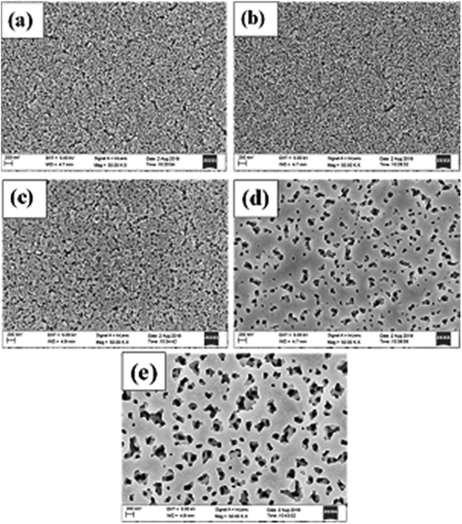 | ||
| Fig. 1 FESEM images of the (a) unimplanted TiO2 and Au-implanted TiO2 at different fluence values: (b) F1, (c) F2, (d) F3 and (e) F4. | ||
The XPS survey spectra of the unimplanted and Au-implanted TiO2 (Fig. S1†) exhibit the presence of the Ti, O and Au elements. The elemental compositions of Ti, O and Au present in all the samples were determined from the area under the curves in the core level XPS spectra of Ti-2p (Fig. S2†), O-1s (Fig. S3†) and Au-4f (Fig. S4†), respectively. The unimplanted TiO2 contained 0.28 and 0.72 atomic %ages of Ti and O, respectively, with the Ti/O ratio of 0.6. In contrast, the implanted TiO2 showed the presence of the additional Au element, and its composition increased with an increase in Au fluence i.e. F1 (0.04%), F2 (0.09%), F3 (0.11%) and F4 (0.42%).
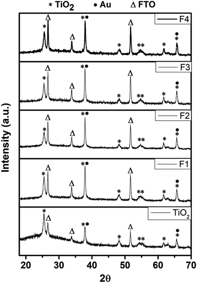
The XRD patterns of the TiO2 and Au-implanted TiO2 were compared, as shown in Fig. 2. The peaks at 25.49°, 38.00°, 48.17°, 54.58°, 55.00°, 61.58° and 65.63° are respectively assigned to the (101), (004), (200), (105), (211), (204) and (116) crystal planes of anatase TiO2 (JCPDS card no. 21-1272).23,43 In addition, the peaks at 26.64°, 33.84° and 51.57° corresponding to the (201), (130) and (312) planes of the FTO substrates (JCPDS card no. 00-030-1375)44 were observed. The Au-implanted TiO2 exhibits similar peaks; however, the intensity of the peaks corresponding to the 2θ values of 38.00° and 65.63° increases with the increasing fluence due to the overlapping45 of the additional (111) and (220) planes of the face-centered cubic Au (JCPDS card no. 04-0784),43,46 respectively. Moreover, the intensity of the peaks at 26.64°, 33.84° and 51.57° increases in the implanted TiO2 due to an increase in the pore size after Au implantation, thus providing more reflections of X-rays from the FTO surface. The sharp and well-defined diffraction peaks confirm the polycrystalline nature of the unimplanted and implanted TiO2.
Fig. 3 depicts the UV-Vis absorption spectra of the N719 dye-loaded unimplanted and Au-implanted TiO2 photoanodes. An absorption band around 307 nm is observed in the spectra of the unimplanted and Au-implanted TiO2 photoanodes, ascribed to the intrinsic inter-band exciton transitions.16,18 The characteristic absorption bands of the N719 dye around 390 and 530 nm were not observed for all the samples as these peaks became suppressed because of the high absorbance at 307 nm. A gradual increase and broadening in the absorbance was observed up to the F3 photoanode, ascribed to the enhanced light absorption of sensitized dye molecules due to the coupling of a strong local field of LSPR around Au and the dipole moment of the dye molecules. Furthermore, the amount of the sensitized dye in the unimplanted and Au-implanted TiO2 was determined through dye desorption experiments by obtaining the absorbance spectra of the N719 dye deloaded from the samples (Fig. 4). The N719 dye molecules showed an absorbance around 390 and 530 nm in all the samples. The amount of dye loading was calculated as follows:47
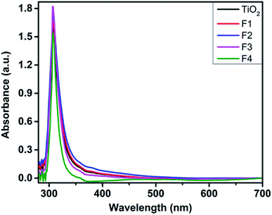 | ||
| Fig. 3 UV-Vis absorption spectra of the N719 dye-loaded unimplanted and Au-implanted TiO2 (F1, F2, F3 and F4) photoanodes. | ||
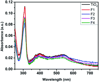 | ||
| Fig. 4 UV-Vis absorption spectra of the N719 dye deloaded from the unimplanted and Au-implanted TiO2 (F1, F2, F3 and F4) photoanodes. | ||
| Sample | Concentration of dye (μM) | Dye loading (×10−8 mol cm−2) |
|---|---|---|
| TiO2 | 1.91 | 2.29 |
| F1 | 1.83 | 2.19 |
| F2 | 1.76 | 2.11 |
| F3 | 1.68 | 2.02 |
| F4 | 1.53 | 1.84 |
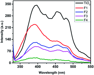
The PL spectra of the unimplanted and Au-implanted photoanodes (Fig. 5) were obtained with λexcitation at 350 nm using a xenon lamp. The unimplanted TiO2 exhibits broad emission peaks at around 395 and 452 nm corresponding to the transitions involving the recombination of electrons trapped at levels within the forbidden band gap of TiO2 arising due to the intrinsic oxygen vacancies.21,48 The Au-implanted TiO2 exhibits similar emission spectra, and its PL intensities are lower than those of the unimplanted TiO2. Furthermore, it is observed that the PL intensity decreases with an increase in fluence (from F1 to F4). The photoluminescence occurs due to the emission of photons by the recombination of photo-generated electrons and holes, which infers a lower recombination rate for the lower-intensity peaks. Thus, the plasmonic TiO2 exhibits a lower charge recombination rate, which is least for the F4 sample. It can be explained on the basis of the formation of Schottky barriers48,49 at the TiO2 and Au (TiO2@Au) interface that help to capture the photo-generated electrons before they recombine with holes by accumulating them around Au. Thus, Au acts as a charge separation center for the photo-generated electrons.45 Moreover, the lifetime of the photo-generated electrons increases (discussed later in the EIS studies); this improves the electron charge transport and inhibits the electron–hole recombination process.
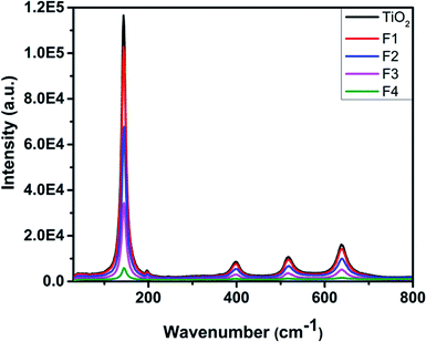
Fig. 6 shows the Raman spectra of the unimplanted and Au-implanted TiO2 obtained at room temperature using a 514 nm argon laser source. The peaks of the unimplanted anatase phase of TiO2 are observed at 145, 200, 403, 520 and 643 cm−1, corresponding to the Eg(1), Eg(2), B1g(1), A1g(1) + B1g(2) and Eg(3) Raman-active phonon modes. The highly intense Raman peak at 145 cm−1 is closely related to the anatase TiO2 single crystal.50 The Au-implanted TiO2 exhibits similar Raman peaks; however, a gradual decrease in their intensities is observed with an increase in fluence; this infers an increase in the number of defects on the TiO2 surface created by the Schottky barriers.45 Au does not possess any specific phonon mode because of its weak Raman scattering power; this suggests that the Au implantation does not alter the phase of TiO2.
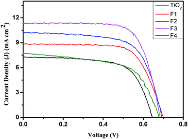
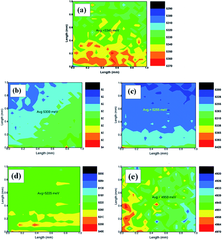
The current density–voltage (J–V) characteristics of DSSCs fabricated with the unimplanted and Au-implanted TiO2 are shown in Fig. 7. The obtained photovoltaic parameters, such as short circuit current density (JSC), open circuit voltage (VOC), fill factor (F.F.) and PCE, summarized in Table 2, signify the beneficial effect of Au implantation on the photovoltaic performance of the DSSCs. The JSC of the Au-implanted TiO2-based DSSC is found to be greater than that of the unimplanted TiO2-based DSSC due to the enhanced light absorption owing to the LSPR of Au. Furthermore, the JSC increases with the increasing fluence up to the F3-based DSSC, and then, a sudden decrease in the JSC is observed due to the decreased dye loading onto the TiO2 surface. Although similar values of VOC are obtained for the plasmonic DSSCs, they are comparatively higher than those of the unimplanted DSSC; this has been explained by the work function measurements. The surface work function ϕ of the unimplanted TiO2 (Fig. 8(a)) has been found to be 5.34 eV, which further decreases upon Au implantation (Fig. 8(b–e), Table 2). This indicates an upward shift in EF induced by the Schottky barriers.51 The upward shift in the EF values of the plasmonic TiO2 confirms the increase in VOC as it is defined as the difference between the EF of the photoanode and the redox potential of the electrolyte (constant herein). The comparatively larger change in the JSC than that in VOC contributes to the enhancement in the PCEs of the implanted DSSCs (Table 2). Thus, the PCEs of the plasmonic DSSCs are found to be higher than those of the unimplanted DSSCs. Furthermore, the PCE increases with an increase in fluence up to 1015 ions cm−2 and suddenly decreases for the F4-based DSSC. Hence, the F3-based DSSC exhibits the maximum PCE of 5.59% with an increment of 44.7% as compared to the TiO2-based DSSC (3.09%).
| Photoanodes | JSC (mA cm−2) | VOC (V) | F.F. | PCE (%) | RS (Ω cm2) | R2 (Ω cm2) | ϕ (eV) |
|---|---|---|---|---|---|---|---|
| TiO2 | 7.23 | 0.65 | 0.65 | 3.09 | 8.47 | 8.57 | 5.34 |
| F1 | 8.80 | 0.70 | 0.75 | 4.72 | 8.87 | 8.87 | 5.30 |
| F2 | 10.15 | 0.69 | 0.68 | 4.84 | 9.60 | 9.00 | 5.25 |
| F3 | 11.29 | 0.69 | 0.71 | 5.59 | 9.90 | 12.40 | 5.22 |
| F4 | 7.71 | 0.69 | 0.59 | 3.15 | 10.10 | 12.48 | 4.95 |
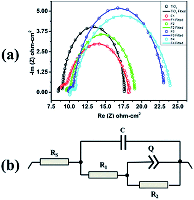
The EIS measurements were performed on the unimplanted and Au-implanted DSSCs to understand the variation in JSC and reduced electron–hole recombination rate through the interfacial electronic charge transfer process. The Nyquist plots (Fig. 9(a)) were obtained for all the DSSCs operated at their respective VOC under illumination and showed two well-defined semicircles. The Nyquist plots fitted with the equivalent circuit model (Fig. 9(b)) provide an estimated value of the total DC resistance comprising the combination of RS, R1 and R2. Herein, R1 corresponds to the electron charge transfer resistance at the CE/electrolyte interface and is determined from the diameter of the first semicircle in the Nyquist plot; moreover, it is almost same for all the DSSCs as the CE is similar in all the devices. The intercept of the high frequency semicircle at the real axis provides the RS value representing the ohmic series resistance influenced by FTO, TiO2 (with and without Au nps), Pt CE, and the electrolyte.19,45 RS increases slightly for the Au-implanted DSSCs as compared to that for the unimplanted DSSC (Table 2) due to an additional resistance offered by the Schottky barriers at the TiO2@Au interface. Furthermore, the RS values show a continuous increase with the increasing fluence (from F1 to F4) due to the presence of more Schottky barriers as the Au content increases in TiO2. The diameter of the Nyquist second semicircle depicts the charge transfer resistance (R2) at the unimplanted and Au-implanted TiO2@N719/electrolyte interface.19 The values of R2 for the Au-implanted DSSCs have been found to be higher than those for the unimplanted DSSCs because of the charge separation ability of Au in the Schottky barriers,21 which prevents the electrons from recombining with the holes at the highest occupied molecular orbital (HOMO) of the N719 dye. Moreover, R2 increases with the increasing fluence; this leads to a reduced electron recombination rate that further contributes to the increased JSC values (Table 2). Although R2 is maximum and the electron hole recombination rate for F4 is least, JSC still decreases for the F4 DSSC because the lower dye-loading generates a lower number of charge carriers for transport throughout the circuit. Thus, the F3-based DSSC with the increased values of RS and R2 exhibits a significantly reduced recombination, resulting in the highest fill factor of 0.71 (Table 2).
Moreover, the electron–hole recombination process at the TiO2@N719/electrolyte interface has been supported through the electron lifetime (τ) measurements. It is observed that the maxima of the characteristic maximum frequency (fmax) of the Nyquist 2nd semicircle shifts towards a lower frequency region with an increase in the Au fluence from the F1 to F4 DSSCs as compared to the case of the unimplanted DSSC. This reveals longer electron lifetime as it is inversely proportional to fmax, i.e.,  , which reduces the electron–hole recombination rate due to the increased Au content in TiO2, characterized by larger R2 values.
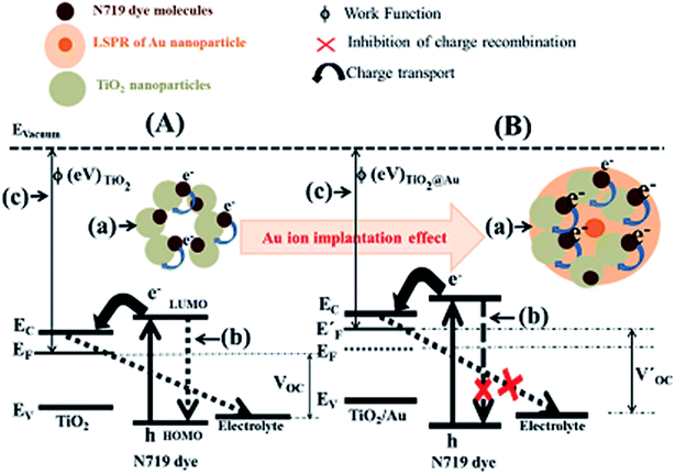
On the basis of the abovementioned morphological, compositional, spectroscopic, J–V and EIS investigations, a plausible mechanism behind the improvement of the PCE of Au-implanted plasmonic DSSCs as compared to that of the unimplanted DSSC has been explained (Fig. 10).
Compared to the Au-implanted photoanodes, a comparatively lower number of photo-generated electrons get excited from the HOMO to LUMO level of the N719 dye (Fig. 10A(a) and B(a)). Some of these electrons recombine with the dye molecules as well as the electrolyte (Fig. 10A(b)) instead of entering the conduction band of TiO2. The lower photo-generated electrons and higher recombination rate resulted in smaller JSC and VOC (Fig. 10A(c)) and consequently smaller FF and PCE of the unimplanted DSSC. In contrast, the plasmonic DSSCs with implanted photoanodes exhibit a comparatively higher number of photo-generated electrons upon absorption of more photons by the N719 dye molecules due to the LSPR effect (Fig. 10B(a)). Further, the formation of the Schottky barriers at the TiO2@Au interface inhibits the back recombination of electrons (Fig. 10B(b)) to provide a comparatively higher JSC. Moreover, the decrease in ϕ of TiO2 upon implantation (Fig. 10B(c)) shifts the EF towards an upward direction and results in an increase of the VOC. Hence, the increase of both JSC and VOC upon implantation results in the improved FF and PCE of the plasmonic DSSCs.
In addition, the photovoltaic parameters improve with the increasing fluence of Au implantation (Table 2) due to comparatively more photo-generated electrons, back recombination inhibition and a decrease in ϕ of TiO2. However, the PCE of the F4-based DSSC is found to be limited by the amount of dye-loading content as the porosity of TiO2 decreases at higher fluence, which further reduces the dye-loading.
4. Conclusion
The electronic and optical properties of TiO2 photoanodes were successfully tuned through Au implantation for the fabrication of highly stable and efficient plasmonic DSSCs. The DSSCs containing TiO2 implanted with 0.11 atomic %age of Au under the fluence of 1015 ions cm−2 showed long-term stability along with improved photovoltaic performance, having the PCE, JSC and VOC values of 5.59%, 11.29 mA cm−2 and 0.69 V as compared to the TiO2-based DSSCs (PCE = 3.09%, JSC = 7.23 mA cm−2 and VOC = 0.65 V, respectively). The increment of 44.7% in the PCE of the plasmonic DSSCs is attributed to the enhanced light absorption and reduced electron hole recombination rate. Thus, ion implantation has the potential to fabricate stable as well as efficient plasmonic DSSCs than the DSSCs containing bare as well as core shell Mnps.Conflicts of interest
There are no conflicts of interest to declare.Acknowledgements
The authors are thankful to Inter University Accelerator Centre, New Delhi, for providing financial support through Project No. UFR-60331. One of the authors, Navdeep Kaur, is thankful to UGC, New Delhi, India, for providing financial assistance in support of the present research work.References
- Q. Hao, C. Wang, H. Huang, W. Li, D. Du, D. Han, T. Qiu and P. K. Chu, Sci. Rep., 2015, 5, 15288 CrossRef CAS PubMed.
- Y. Wang, L. Liu, L. Xu, C. Meng and W. Zhu, J. Appl. Phys., 2013, 113, 174311 CrossRef.
- S. T. Nishanthi, S. Iyyapushpam, B. Sundarakannan, E. Subramanian and D. Pathinettam Padiyan, J. Power Sources, 2015, 274, 885–893 CrossRef CAS.
- S. Hirose, S. Ueda and N. Ohashi, J. Appl. Phys., 2019, 125, 095301 CrossRef.
- P. Zimmermann, A. Hötger, N. Fernandez, A. Nolinder, K. Müller, J. J. Finley and A. W. Holleitner, Nano Lett., 2019, 19, 1172–1178 CrossRef PubMed.
- Y. Shao, X. Li, L. Wu and D. Wang, J. Appl. Phys., 2018, 125, 013101 CrossRef.
- J. Luo, J. Chen, H. Wang and H. Liu, J. Power Sources, 2016, 303, 287–293 CrossRef CAS.
- H. Wang, F. Chen, W. Li and T. Tian, J. Power Sources, 2015, 287, 150–157 CrossRef CAS.
- N. Okada, N. Morishita, A. Mori, T. Tsukada, K. Tateishi, K. Okamoto and K. Tadatomo, J. Appl. Phys., 2017, 121, 153102 CrossRef.
- T. Plint, B. H. Lessard and T. P. Bender, J. Appl. Phys., 2016, 119, 145502 CrossRef.
- O. A. Yeshchenko, S. Z. Malynych, S. O. Polomarev, Y. Galabura, G. Chumanov and I. Luzinov, RSC Adv., 2019, 9, 8498–8506 RSC.
- P. Halkare, N. Punjabi, J. Wangchuk, A. Nair, K. Kondabagil and S. Mukherji, Sens. Actuators, B, 2019, 281, 643–651 CrossRef CAS.
- N. J. Hogan, A. S. Urban, C. Ayala-Orozco, A. Pimpinelli, P. Nordlander and N. J. Halas, Nano Lett., 2014, 14, 4640–4645 CrossRef CAS PubMed.
- J. Kim, Lab Chip, 2012, 12, 3611–3623 RSC.
- Tanvi, A. Mahajan, R. K. Bedi, S. Kumar, V. Saxena, A. Singh and D. K. Aswal, RSC Adv., 2016, 6, 48064–48071 RSC.
- W. Hou, P. Pavaskar, Z. Liu, J. Theiss, M. Aykol and S. B. Cronin, Energy Environ. Sci., 2011, 4, 4650–4655 RSC.
- B. O'Regan and M. Grätzel, Nature, 1991, 353, 737 CrossRef.
- Y. H. Jang, Y. J. Jang, S. T. Kochuveedu, M. Byun, Z. Lin and D. H. Kim, Nanoscale, 2014, 6, 1823–1832 RSC.
- S. Chang, Q. Li, X. Xiao, K. Y. Wong and T. Chen, Energy Environ. Sci., 2012, 5, 9444–9448 RSC.
- Y. Wang, J. Zhai and Y. Song, RSC Adv., 2015, 5, 210–214 RSC.
- H. Dong, Z. Wu, A. El-Shafei, B. Xia, J. Xi, S. Ning, B. Jiao and X. Hou, J. Mater. Chem. A, 2015, 3, 4659–4668 RSC.
- Y. Li, H. Wang, Q. Feng, G. Zhou and Z.-S. Wang, Gold nanoparticles inlaid TiO2 photoanodes: a superior candidate for high-efficiency dye-sensitized solar cells, 2013 Search PubMed.
- H.-W. Chen, C.-Y. Hong, C.-W. Kung, C.-Y. Mou, K. C. W. Wu and K.-C. Ho, J. Power Sources, 2015, 288, 221–228 CrossRef CAS.
- S. Muduli, O. Game, V. Dhas, K. Vijayamohanan, K. A. Bogle, N. Valanoor and S. B. Ogale, Sol. Energy, 2012, 86, 1428–1434 CrossRef CAS.
- N. Chander, A. F. Khan, E. Thouti, S. K. Sardana, P. S. Chandrasekhar, V. Dutta and V. K. Komarala, Sol. Energy, 2014, 109, 11–23 CrossRef CAS.
- L. Zhao, C. Zhong, Y. Wang, S. Wang, B. Dong and L. Wan, J. Power Sources, 2015, 292, 49–57 CrossRef CAS.
- H. Ran, J. Fan, X. Zhang, J. Mao and G. Shao, Enhanced performances of dye-sensitized solar cells based on Au–TiO2 and Ag–TiO2 plasmonic hybrid nanocomposites, 2017 Search PubMed.
- Y. Li, H. Wang, Q. Feng, G. Zhou and Z.-S. Wang, Energy Environ. Sci., 2013, 6, 2156–2165 RSC.
- C. Hägglund, M. Zäch and B. Kasemo, Appl. Phys. Lett., 2008, 92, 013113 CrossRef.
- Tanvi, A. Mahajan, R. K. Bedi, S. Kumar, V. Saxena and D. K. Aswal, J. Appl. Phys., 2015, 117, 083111 CrossRef.
- S. D. Standridge, G. C. Schatz and J. T. Hupp, J. Am. Chem. Soc., 2009, 131, 8407–8409 CrossRef CAS PubMed.
- H. Choi, W. T. Chen and P. V. Kamat, ACS Nano, 2012, 6, 4418–4427 CrossRef CAS PubMed.
- Y.-Z. Zheng, X. Tao, J.-W. Zhang, X.-S. Lai and N. Li, J. Power Sources, 2018, 376, 26–32 CrossRef CAS.
- L. Bai, M. Li, K. Guo, M. Luoshan, H. F. Mehnane, L. Pei, M. Pan, L. Liao and X. Zhao, J. Power Sources, 2014, 272, 1100–1105 CrossRef CAS.
- S. D. Standridge, G. C. Schatz and J. T. Hupp, Langmuir, 2009, 25, 2596–2600 CrossRef CAS PubMed.
- J. Du, J. Qi, D. Wang and Z. Tang, Energy Environ. Sci., 2012, 5, 6914–6918 RSC.
- Q. Xu, F. Liu, Y. Liu, K. Cui, X. Feng, W. Zhang and Y. Huang, Sci. Rep., 2013, 3, 2112 CrossRef PubMed.
- F. Singh, S. Mohapatra, J. P. Stoquert, D. K. Avasthi and J. C. Pivin, Presented in part at the The Seventh International Symposium on Swift Heavy Ions in Matter, Lyon, France, 2008 Search PubMed.
- Y. K. Mishra, F. Singh, D. K. Avasthi, J. C. Pivin, D. Malinovska and E. Pippel, Appl. Phys. Lett., 2007, 91, 063103 CrossRef.
- A. Kumar, M. K. Jaiswal, D. Kanjilal, R. K. Joshi and T. Mohanty, Appl. Phys. Lett., 2011, 99, 013109 CrossRef.
- J. Luo, J. Zhou, H. Guo, W. Yang, B. Liao, W. Shi and Y. Chen, RSC Adv., 2014, 4, 56318–56322 RSC.
- C. Dufour, V. Khomrenkov, Y. Y. Wang, Z. G. Wang, F. Aumayr and M. Toulemonde, J. Phys.: Condens. Matter, 2017, 29, 095001 CrossRef CAS PubMed.
- L. Zhang and Z.-S. Wang, J. Mater. Chem. C, 2016, 4, 3614–3620 RSC.
- M. A. Al-Azawi, N. Bidin, M. Bououdina and S. M. Mohammad, Sol. Energy, 2016, 126, 93–104 CrossRef CAS.
- S. P. Lim, A. Pandikumar, N. M. Huang and H. N. Lim, RSC Adv., 2015, 5, 44398–44407 RSC.
- S. W. Sheehan, H. Noh, G. W. Brudvig, H. Cao and C. A. Schmuttenmaer, J. Phys. Chem. C, 2013, 117, 927–934 CrossRef CAS.
- V. Saxena, P. Veerender, A. K. Chauhan, P. Jha, D. K. Aswal and S. K. Gupta, Appl. Phys. Lett., 2012, 100, 133303 CrossRef.
- M. C. Mathpal, P. Kumar, A. K. Tripathi, R. Balasubramaniyan, M. K. Singh, J. S. Chung and A. Agarwal, New J. Chem., 2015, 39, 6522–6530 RSC.
- P. Nbelayim, G. Kawamura, W. Kian Tan, H. Muto and A. Matsuda, Sci. Rep., 2017, 7, 15690 CrossRef PubMed.
- Y. L. Du, Y. Deng and M. S. Zhang, J. Phys. Chem. Solids, 2006, 67, 2405–2408 CrossRef CAS.
- A. Kumar, A. S. Patel and T. Mohanty, J. Phys. Chem. C, 2012, 116, 20404–20408 CrossRef CAS.
Footnote |
| † Electronic supplementary information (ESI) available. See DOI: 10.1039/c9ra02657f |
| This journal is © The Royal Society of Chemistry 2019 |

