
 Open Access Article
 This Open Access Article is licensed under a Creative Commons Attribution-Non Commercial 3.0 Unported Licence
Nitrogen doped small molecular structures of nano-graphene for high-performance anodes suitable for lithium ion storage†
Zhixiang Lva,
Zhou Wangb and
Jianhong Chen *a
*a
aDepartment of Pharmacy, Danyang People’s Hospital, Danyang, 212300, P. R. China. E-mail: dyjianhongchen@163.com
bCollege of Vanadium and Titanium, Panzhihua University, Panzhihua, 617000, P. R. China
First published on 19th July 2019
Abstract
N-doped nano-graphene derivatives were prepared by a bottom-up organic synthesis method. Through d-spacing modification and dynamic self-assembly of the structures of these molecules, ideal lithium ion-transfer aggregation formed between each monolayer. Rapid ion/electron transfer and maintenance of the structural integrity during repeated ion insertion/extraction occurred due to the lack of a covalent interaction force among the assembled structures. The doping level, i.e., number of N atoms, had a significant influence on the molecular self-assembled structures through hierarchical self-assembly. As the N concentration increased, the d-space between the nanosheets increased from 3.4 to 4.3. The capacity of the nano-graphene increased greatly from N-doping nano-graphene (NG-N4) to 1800 mA h g−1, indicating that the capacity is related to the structure. Moreover, the N-doping site of nano-graphene was defined and the relationship between the performance and structure was determined.
1. Introduction
Over the ages, nano-graphene composites have been extensively investigated, and core–shell structures with carbonaceous material-encapsulated silicon or metal nanostructures have been proposed.1–4 Since Professors Andre Konstantin Geim and Konstantin Sergeevich first reported stable graphene in 2004 using the deceptively simple Scotch® tape method, it has been studied by many researchers,5,6 other methods of synthesis including liquid phase and thermal exfoliation,7–9 chemical vapor deposition,10–12 and synthesis on SiC13,14 have been reported.In addition, there are many problems which still remain unresolved, such as the high temperatures and substrates and super-high vacuum conditions needed for epitaxial growth, the uncontrollable number of graphene layers with CVD, the uncontrollable defect and low single layer graphene ratio for liquid-phase exfoliation, and the uncontrollable size and shape of graphene obtained from mechanical exfoliation. Therefore, to overcome these problems, new approaches are needed to produce high-quality graphene. Structurally well-defined nano-graphene can be modified and functionalized in a controllable manner.
In this paper, we have designed a bottom-up organic synthesis method. The sp2-hybridized nitrogen atoms on one side enhanced the conjugation between the carbon and nitrogen atoms without defects in the hexabenzocoronene planar structure and the electrostatic interactions between the lone pair of electrons of nitrogen atoms and electron cloud of carbon atoms drive the planar structure. These geometric and electronic properties resulted in optimal dynamic self-assembled structures with a large d-spacing between the layers.
2. Experimental
Materials and characterization
Powder X-ray diffraction (XRD, Rigaku Smartlab) of the samples were recorded using Cu Kα radiation. The morphology and lattice fringe were observed by a scanning electron microscope (SEM, JEOL JCM-6000Plus), transmission electron microscope (TEM, JEOL H-7000) and a high resolution transmission electron microscope (HRTEM, JEOL JEM-2100).Electrochemical measurements
Electrochemical measurements were performed on the Shanghai Chenhua CHI660e system. A three-electrode system is used, a platinum wire for the counter electrode, a platinum plate with a fixed area for the working electrode, and a saturated calomel electrode for the reference electrode. The concentration of the supporting electrolyte tetra-n-butylammonium perchlorate (TBAP) was 0.1 mol L−1, and the analytical pure solvent was acetonitrile (ACN). Firstly, the platinum carbon electrode held vertically on the circular gauze on the glass brick (paint “8”, 0.05 μm aluminum powder and water as friction agent) was polished; secondly, the white aluminum was rinsed off with clean water, ultrasonicated with acetone for 1 minute, and wash the earball was blown dried. According to the conventional electrochemical concentration of graphene, the series of NG-N0–4 compounds were prepared at 1 mg mL−1, respectively. Then, the suspension of the NG-N0–4 sample was dropped onto the surface of the glassy carbon electrode, and the solvent was naturally evaporated to dryness. Then 0.1 M tetra-n-butylammonium perchlorate and 0.1 mM ferrocene electrolyte solution were scanned at a scan rate of 0.1 mV s−1.3. Results and discussion
This paper reports on the mono-nitrogen, di-nitrogen, tri-nitrogen and tetra-nitrogen, on carbon–carbon or carbon–nitrogen combined with considerable π–π conjugate chemical bonding. The preparation of NG-N0–4 consisted of a series of reactions, such as Suzuki, Sonogashira, Diels–Alder reaction and deprotonation under basic conditions to give 0–4 intermediates in unsatisfactory yields (38–52%). Finally, the NG-N0–4 series compounds were generated from intermediates and nitromethane with treatment with a Lewis reagent which gave the target compounds in a similarly low yield (28–37%), as shown in Scheme 1 (see ESI†).11 The reaction solution was quenched with methanol, followed by repeated dissolution and precipitation with methylene chloride/methanol. The crude compounds were collected and washed with methanol/acetone/dichloromethane (1![[thin space (1/6-em)]](https://www.rsc.org/images/entities/char_2009.gif) :1:1) to give NG-N0–4 as the corresponding solids. As a result, the NG-N0–4 structure was determined from the mass spectra recorded on a MALDI-TOF-Mass. All these spectroscopic results are illustrated in the ESI (Fig. S1–S4†) and are in good agreement with the proposed molecular structures, confirming the successful preparation of NG-N0–4. These NG-N0–4 compounds with various functional groups exhibited excellent thermal stability without significant mass loss up to 260 °C under a N2 atmosphere.
:1:1) to give NG-N0–4 as the corresponding solids. As a result, the NG-N0–4 structure was determined from the mass spectra recorded on a MALDI-TOF-Mass. All these spectroscopic results are illustrated in the ESI (Fig. S1–S4†) and are in good agreement with the proposed molecular structures, confirming the successful preparation of NG-N0–4. These NG-N0–4 compounds with various functional groups exhibited excellent thermal stability without significant mass loss up to 260 °C under a N2 atmosphere.
Based on the design, small-molecular nano-graphene materials have the characteristics of a clear and simple structure. In particular, nano-graphene molecules have dynamic self-assembly modes that are organized in an orderly manner, and are capable of yielding a series of robust dynamic hierarchical self-assembled structures that remain unchanged throughout the long-term charging–discharging cycles. In contrast, these dynamic hierarchical NG assemblies can overcome the restacking issues observed in traditional sheets, and achieve high Li storage capacity and diffusivity, and simultaneously address the long-term stability issues. More importantly, such synthesized NGs with well-defined molecular and electronic structures can serve as ideal model systems to provide a fundamental understanding of the correlations among the functionalized groups, and the resulting electronic property, d-spacing, and electrochemical properties for energy storage in LIBs (Fig. 1). These results show that the introduction of functional groups affects the geometry of NG-N0–4 significantly. Moreover, the nanoparticles between the nanoclusters, as determined by SEM, had a uniform size (Fig. 2a). This shows the tendency of the structure and size of nanoparticles with differences in the distance between the nano-structured d-spacing by nitrogen incorporation.15–17 The structural characteristics of N-doped nano-graphene were determined by XRD, as shown in Fig. 2b. The XRD peaks at 21.83°, 21.56°, 21.42°, and 21.17° were assigned, except for the broad peak from NG-N0 at 25.66°. The addition of nitrogen resulted in a peak shift from 21.17° for graphene to 21.83°. The broad peak was ascribed to partial nitrogen-containing groups. This was validated by the corresponding XRD patterns that revealed a smaller peak angle with increasing nitrogen incorporation (nitrogen unit) and NG-N0–4 using MALDI-TOF. These results are illustrated in ESI (Fig. S1–S4†) and are in agreement with the proposed molecular structures, confirming the successful preparation of the NG-N0–4 series. The XRD patterns of the as-synthesized sample are consistent with those of the simulated ones (Fig. 2c).18
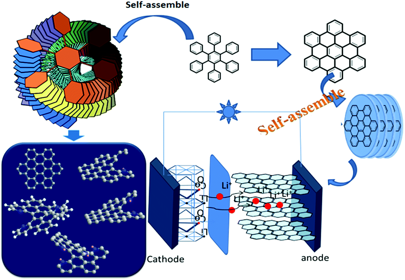 | ||
| Fig. 1 Schematic diagram of the NG-N0–4 Li-ion storage process. First, schematic illustration of NG-N0–4 assemblies. Second, the different molecular structures of NG-N0–4 induced by different layer d-spacing. Finally, lithium ions pass through different layers depending on the wide d-spacing structure, such as NG-N4. | ||
 | ||
| Fig. 2 Structural characterization. SEM images of (a) NG-N0–4; (b) XRD patterns of NG-N0–4 samples; (c) XRD patterns of NG-N0–4 precursors in comparison with the simulated. | ||
On the other hand, the HRTEM images indicate that the NG-N0–4 nanoparticles bind with each other and the spacing of the adjacent lattice planes have the appearance of a fingerprint (Fig. 3). The concentric diffraction rings in the selected area electron diffraction (SAED) pattern confirms the polycrystalline nature of NG-N0–4. Furthermore, HRTEM showed that most of the graphene-like walls consisted of a few layers (<10 layers), indicating typically ultrathin structures. The layer-by-layer structures of the NG-N0–4 and the perfect d-spacing between the layers resulted in excellent performance as LIB anode materials.19 The dynamic hierarchical self-assembly multi-structures experienced arranged and rearranged processes (inset in Fig. 3a–j) highlighting the optimal d-spacing between the layers for lithium ion storage. The molecules assemble in different stacking modes. The nano-graphene sheets have a twist-like scissor appearance to lower the energy of the molecules due to the spatial steric hindrance between the single electron pair outside the nitrogen atoms. Some molecules will arrange along the scissor blade, which are revealed in the TEM images as d-spacings of 0.34 nm to 0.42 nm for NG-N0–4. Some molecules assembled with a scissor blade and scissor handle, which are shown in the TEM image with a d-spacing of 0.43 nm, such as NG-N4 (Fig. 3). In particular, N-doped nano-graphene groups attached to the flakes have corresponding d-spacings of 3.4, 3.5, 3.8, 3.6, and 4.3 Å, respectively. The average d-spacing around 3.4–4.3 Å for these NG-N0–4 increased gradually compared to that of the pristine graphite (3.3–3.4 Å). Moreover, the d-spacing between flakes, as determined by TEM, is consistent with the size of the functional groups (NG-N0 ≈ NG-N4), which is also validated by the corresponding XRD measurements and reveals a smaller peak angle with the increasing size of the substituents (Fig. 2b). This paper reports a multi-diffusing process of lithium ions as the dynamic structure providing dynamic diffusion paths. TEM suggested lithium diffused between the layers and has the ability to go through the sheets, which increases lithium ion diffusion considerably.20,21
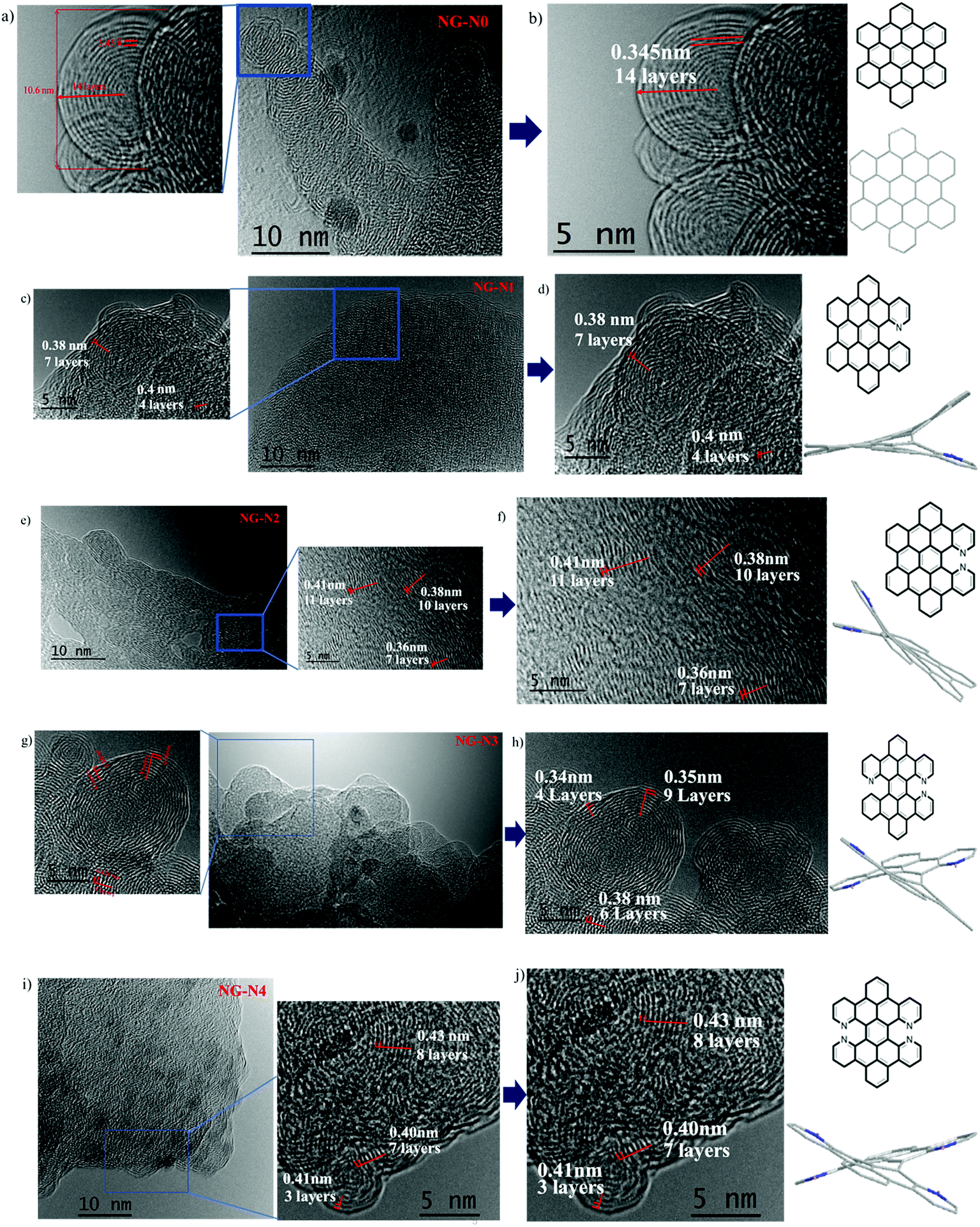 | ||
| Fig. 3 HRTEM image of NG-N0–4, (a–j) with their dynamic hierarchical self-assembly interlayer number and various layer d-spacing patterns. | ||
In addition, to operate the lithium-ion batteries at a high potential, the long-term stability and potential energy were determined by cyclic voltammetry (Fig. 4). Therefore, the cells were assembled using an unscratched silver current collector as the cathode and Li as the anode, and the CV was conducted at a scan rate of 0.1 mV s−1 between 0 and 3 V for three cycles, as shown in (Fig. 4b). As expected, when the cell voltage was scanned up to 3 V, all the electrolytes underwent severe oxidation and the current densities increased significantly after 0.8 V, which decreased with cycling due to passivation of the electrode surfaces. On the other hand, a clear difference in the pitching and passivation peak of Ag at ∼1.9 V was observed.22
 | ||
| Fig. 4 Cyclic voltammograms (CVs) of the ferrocene current collector disc vs. silver metal in the electrolyte (a) without additive, and (b), (NG-N0), (NG-N1), (NG-N2), (NG-N3) and (NG-N4) electrodes at a scan rate of 0.1 mV s−1. | ||
According to the above description, CV (Li+/Li vs. Ag/AgCl) was conducted to understand the lithium storage behavior. Fig. 5 presents the CV curves of five NG-N0–4 samples analyzed at the same scan rates (0.1 mV s−1). The CV curves of NG-N0–4 displayed redox peaks with slight shifts with increasing scan rates, indicating the effect of nitrogen atoms. The CV curves of NG-N0–4 (Fig. 4) showed rectangular shapes with increasing scan rates. The twisted rectangular shape at the fast scan rate may be due to the poor electronic nature of amorphous materials, as proposed by Wang and Tucek et al.23,24 The measured HOMO energy at a fixed potential (V) can be separated into oxidation increases (V1), standard oxidation effects (V2), and standard reduction effects (V3) (eqn (1)), which can characterize the capacity contribution of each part quantitatively.25,26
| HOMO (V) = V1 + V2 + V3 | (1) |
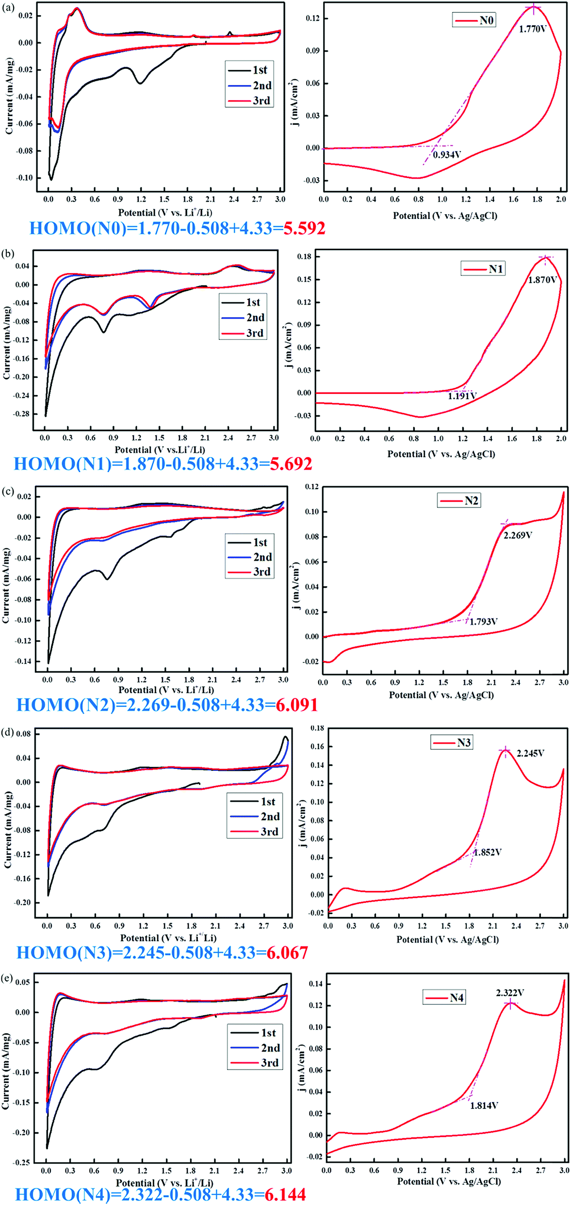 | ||
| Fig. 5 (a–e) Cyclic voltammograms (CVs) of (NG-N0–4) anode in LIB as a function of attached groups, and comparison of oxidation energy HOMO values with the cyclic voltammograms of the nanographenes in acetonitrile using tetrabutylammonium perchloride as electrolyte. | ||
The anion/radical anion with an electron donating functional group leads to a homogeneous/uniform electron distribution throughout the flake, which is beneficial for maximizing the number of Li+ ions incorporated into the NG-N0–4. The charging process (Li+ transfer) in NG-N0–4 anodes requires stabilization. The calculated stabilization HOMO energy of the NG-N0–4 radical anode varied form 5.592 (NG-N0) to 6.144 eV (NG-N4), as shown in Fig. 5. This means that the HOMO electron is in a higher energy state; therefore, it is transferred more easily to Li+. The magnitude follows the trend of NG-N0 < NG-N1 < NG-N2 < NG-N3 < NG-N4. Hence, the charge capacity is directly associated with the electron donating/withdrawing nature of the functional group.
Previous studies have reported the synthesis of non-porous three-dimensional N-doped graphene (3D-NG) via a solvothermal process with a discharge specific capacity of 792 mA h g−1 after 145 cycles at 600 mA g−1 and low capacity fading rate (0.05% per cycle). Interestingly, the composites still retained a capacity of 671 mA h g−1 after 200 cycles, even at a high rate of 1500 mA g−1.27–30 In this study, the voltage profiles were measured by five different nano-materials but a remarkable rate performance was also obtained from the cycling test. Fig. 6 shows the rate capacity of the electrode at different NG-N0–4 materials and different current densities and Fig. 6a and b shows the corresponding voltage profiles. The measurement capacity of the NG-N0–4 materials at 100 cycles, and the corresponding capacity was 1928, 1108, 824, 596, and 200 mA h g−1, respectively. Upon each stage, the capacity could maintain good reversibility and deliver a coulombic efficiency of more than 96%. A capacity of 1934 mA h g−1 was recorded when the current density gradually returned, which is consistent with the initial value (Fig. S5†).
 | ||
| Fig. 6 (a–e) The galvanostatic discharge–charge voltage profiles of nanographene anode (NG-N0–4) as a function of cycling numbers. | ||
In the past, the main structural factor influencing lithium absorption in nano-graphene thin materials was the d-spacing in laminar carbon structures. The d-spacing between the carbon layers can be occupied by lithium. Moreover, multiple layers can be formed on the carbon surface, and even interact with functional groups, such as nitrogen attached to graphene sheets. This is because lithium ions can combine easily with the non-covalent electrons in the outer layer of nitrogen. In addition, nitrogen-containing functional groups contribute directly to the increase in the level of Li incorporation because Li can complex directly with a nitrogen atom to form a low energy ionic bond.31–34 Fig. 7 shows the effects of functional groups on battery performance. Among the NG-N0–4, the highest capacity was measured with the nitrogen-functionalized NG-N4 anode, followed by NG-N4 > NG-N3 > NG-N2 > NG-N1 > NG-N0 (Fig. 7a–d). The cycling performance measurements of 0.2 A g−1 and 2 A g−1 showed that NG-N4 had the maximum discharge capacity after 70, 100 and 200 different cycles (Fig. 7). In particular, the performance of multi-nitrogen-doped NG-N4 materials was the most outstanding. In addition, increasing the capacity in the circulation can be attributed to the continuous activation of electrode materials in circulation, and the electrolyte permeating the electrode materials gradually, which is common in graphene materials. In terms of the specific capacity, rate performance and cycle stability, the storage capacity of NG-N1–4 lithium was better than that of nano-graphene anode materials reported previously.35–38 The significantly enhanced electrochemical performance for lithium storage highlights the unique architecture of NG-N1–4, which encourages further study of its characteristics.
 | ||
| Fig. 7 Capacity of NG-N0–4 galvanostatic charging–discharging cycles. The cycling performance of NG-N0–4 included to make a comparison between (a) and (b) 2 A g−1 and (c) and (d) 0.2 A g−1 with 70 cycles, 100 cycles, and 200 cycles. | ||
In addition to the specific capacity and cycling stability, the rate properties of five graphite-dilute materials, NG-N0, NG-N1, NG-N2, NG-N3, and NG-N4, were studied. As shown in (Fig. 8), measurements were made at a rate performance of 0.2 A g−1, 0.5 A g−1, 1 A g−1, and 2 A g−1, respectively. In particular, the NG-N4 hetero-structures delivered reversible capacities as high as 1802, 1789, 1721 and 1654 mA h g−1, respectively. Even at a high rate of 5 A g−1, the reversible capacity was still up to 1382 mA h g−1. After repeated cycling, the reversible capacity can return to 1800 mA h g−1 immediately after the current density is relaxed to 0.2 A g−1.
 | ||
| Fig. 8 Cycling performance at various current densities as indicated by the corresponding number: rate performance of NG-N0, NG-N1, NG-N2, NG-N3 and NG-N4. | ||
The range of the corresponding capacity value of each sample is significantly different. This shows that the structural specific changes are caused by the N-doping effect, the NG-N4 anode demonstrated the best rate performance.39,40 Therefore, in the NG-N0–4 assemblies, the optimal d-spacing (NG-N4) leads to a favored Li binding energy and Li diffusion, along with an increased electron density to maximize Li incorporation with excellent rate performance. These experimental results clearly show that the NG anodes can maintain structural stability during the Li insertion/extraction with very high capacity and high rate performance, which are key to the development of highly efficient LIBs.
4. Conclusion
A series of N-doped nano-graphene derivatives, such as no additive-N, mono-N, di-N, tri-N, and tetra-N, were synthesized by Sonogashira metal coupling, resulting in six-membered cyclization and deprotonation-linked multistep organic and organic metal synthesis routes using pyridine as the starting material. The N-doping NG-N4 anode exhibited a very high capacity of 1800 mA h g−1, which was almost four times larger than that of the without N-doping anode 584 mA h g−1. A high-precision instrumentation, such as SEM, HRTEM, and CV, showed the good structure durability and smaller charge transfer resistance of the NG-N4, which should be responsible for its excellent electrochemical performance, as well as excellent stability and charge–discharge cycles. These results clearly demonstrate a structure–property relationship between the nature of the functional groups and Li storage capacity. In particular, the results obtained from substantial HOMO calculations were in good agreement with the electrochemical and battery measurements, identifying the mechanism on how the NG-N0–4 electronic and geometric structures dominate the overall battery performance.Conflicts of interest
The authors declare that they have no competing interests.Acknowledgements
This study financially by the Science and Technology support project of Zhenjiang (Grant No. FZ2018005).References
- A. Dato, J. Mater. Res., 2019, 34, 214–230 CrossRef CAS.
- M. C. Lewin, F. Baeumer, A. Gunkel, F. Schwedt, J. Gaussmann, P. Wueppen, B. Meuffels, J. Jungbluth, R. Mayer, R. W. Dittmann and T. Taubner, Adv. Funct. Mater., 2018, 28, 1802834 CrossRef.
- S. Z. Wang, J. X. Liao, X. F. Yang, J. N. Liang, Q. Sun, J. W. Liang, F. P. Zhao, A. Koo, F. P. Kong and Y. Yao, Nano Energy, 2019, 57, 230–240 CrossRef CAS.
- S. Z. Wang, H. Y. Chen, J. X. Liao, Q. Sun, F. P. Zhao, J. Luo, X. T. Lin, X. B. Niu, M. Q. Wu and R. Y. Li, ACS Energy Lett., 2019, 4, 755–762 CrossRef CAS.
- M. W. Zhang, C. Y. Hou, A. Halder, H. Z. Wang and Q. J. Chi, Mater. Chem. Front., 2017, 1, 37–60 RSC.
- M. F. El-Kady, Y. L. Shao and R. B. Kaner, Nat. Rev. Mater., 2016, 1, 16033 CrossRef CAS.
- Y. Liang, D. S. Yang and J. H. Cui, New J. Chem., 2017, 41, 13692–13699 RSC.
- J. K. Yan, Y. Y. Wang, W. Y. Qiu, H. L. Ma, Z. B. Wang and J. Y. Wu, Crit. Rev. Food Sci. Nutr., 2018, 58, 2416–2431 CrossRef.
- Y. S. Feng, Y. Zhu, J. Y. Wan, X. Yang, C. K. Firempong, J. N. Yu and X. M. Xu, J. Funct. Foods, 2018, 44, 137–145 CrossRef CAS.
- M. T. Rashid, M. M. Hashim, A. Wali, H. L. Ma, L. N. Guo and X. Jian, J. Food Saf. Food Qual., 2018, 69, 19–25 Search PubMed.
- D. Zhang, M. Z. Du, Y. Wei, C. T. Wang and L. Q. Shen, J. Food Biochem., 2018, 42, 5 Search PubMed.
- F. Xiong, C. H. Dai, F. R. Hou, P. P. Zhu, R. H. He and H. L. Ma, Czech J. Food Sci., 2018, 36, 88–97 CrossRef CAS.
- I. Ayim, H. L. Ma, E. A. Alenyorege, Z. S. Ali, P. O. Donkor and C. S. Zhou, J. Food Meas. Charact., 2018, 12, 2695–2707 CrossRef.
- Z. Y. Zuo, X. G. Li, C. Xu, J. J. Yang, X. C. Zhu, S. Q. Liu, F. B. Song, F. L. Liu and H. P. Mao, Plant, Soil Environ., 2017, 63, 348–354 CrossRef CAS.
- J. N. Chen, L. Sun, Y. Cheng, Z. C. Lu, K. Shao, T. T. Li, C. Hu and H. Y. Han, ACS Appl. Mater. Interfaces, 2016, 8, 24057–24070 CrossRef CAS.
- R. J. Liu, D. Chen, H. X. Fu, P. X. Lv, D. Zhang and Y. J. He, J. Nanomed. Nanotechnol., 2017, 17, 893–899 CAS.
- R. J. Liu, Y. L. Cheng, Y. Li, Q. Zhang, B. Jia, D. S. Wang and R. Fan, J. Nanomed. Nanotechnol., 2017, 17, 2899–2905 CrossRef CAS.
- R. J. Liu, P. X. Lv, H. X. Fu, R. Z. Lu, X. Y. Wu and Y. N. Lu, J. Nanomed. Nanotechnol., 2017, 17, 4755–4762 CAS.
- Q. M. Yu, S. Pan, W. Huang and R. J. Liu, J. Nanomed. Nanotechnol., 2019, 19, 2449–2452 CAS.
- H. P. Zhou, X. Ye, W. Huang, M. Q. Wu, L. N. Mao, B. Yu, S. Xu, I. Levchenko and K. Bazaka, Wearable, Flexible, ACS Appl. Mater. Interfaces, 2019, 11, 15122–15132 CrossRef CAS.
- Y. Kang, W. C. Li, T. Ma, X. C. Huang, Y. P. Mo, Z. Y. Chu, Z. J. Zhang and G. T. Feng, Compos. Sci. Technol., 2019, 174, 184–193 CrossRef CAS.
- H. Fayyaz, I. Muhammad, S. Aisha, R. M. Khalil, R. Arif, M. Anwar, M. A. Sattar, N. A. Niaz, H. Ullah and N. Ahmad, Surf. Rev. Lett., 2019, 26, 1850142 CrossRef.
- S. Q. Wang, X. Hu, J. Goniakowski, C. Noguera and M. R. Castell, Nanoscale, 2019, 11, 2412–2422 RSC.
- J. Tucek, K. Hola, M. Otyepka and R. Zboril, CHEMagazin, 2017, 27, 8–12 CAS.
- L. P. Chen, L. J. Wang, Z. G. Shuai and D. Beljonne, J. Phys. Chem. Lett., 2013, 4, 2158–2165 CrossRef CAS.
- J. I. Martinez, I. Cabria, M. J. Lopez and J. A. Alonso, J. Phys. Chem. C, 2009, 113, 939–941 CrossRef CAS.
- A. F. Zatsepin, E. A. Buntov, D. A. Zatsepin, D. A. Boqizoda, M. B. Guseva, S. P. Vyatkina and A. V. Kas’yanova, Phys. At. Nucl., 2018, 81, 1660–1663 CrossRef CAS.
- L. Q. Zhao, S.-T. Yang, A. Yilihamu and D. Y. Wu, Rev. Inorg. Chem., 2019, 39, 47–76 CAS.
- L. Wang, J. Q. Bi, W. L. Wang, Y. F. Chen, R. Liu and X. N. Sun, Ceram. Int., 2019, 45, 8081–8086 CrossRef CAS.
- S. S. Li, Z. Wang and G. F. Jin, Mater. Res. Express, 2019, 6, 563–568 Search PubMed.
- D. W. He, F. Y. Xiao, Z. Wang, A. L. He, R. J. Liu and G. F. Jin, Nanoscale Res. Lett., 2019, 14, 1–8 CrossRef CAS.
- Q. L. Wei, Q. Q. Wang, Q. D. Li, Q. Y. An, Y. L. Zhao, Z. Peng, Y. L. Jiang, S. S. Tan, M. Y. Yan and L. Q. Mai, Nano Energy, 2018, 47, 294–300 CrossRef CAS.
- J. H. Han, P. Liu, Y. Ito, X. W. Guo, A. Hirata, T. Fujita and M. W. Chen, Nano Energy, 2018, 45, 273–279 CrossRef CAS.
- C. P. Andersen, H. Hu, G. Qiu, V. Kalra and Y. Sun, J. Electrochem. Soc., 2015, 162, A1135–A1145 CrossRef CAS.
- D. Z. Chen, H. G. Quan, J. F. Liang and L. Guo, Nanoscale, 2013, 5, 9684–9689 RSC.
- M. M. Zhen, X. J. Guo, G. D. Gao, Z. Zhou and L. Liu, Chem. Commun., 2014, 50, 11915–11918 RSC.
- Z. Q. Wang, M. Zhang and J. Zhou, ACS Appl. Mater. Interfaces, 2016, 8, 11507–11515 CrossRef CAS.
- K. Wu, B. W. Shi, L. Y. Qi, Y. Y. Mi, B. Zhao, C. K. Yang, Q. Wang, H. Tang, J. Lu and W. Liu, Electrochim. Acta, 2018, 291, 24–30 CrossRef CAS.
- C. Li, N. Na, Z. M. Sheng, H. Huang, Z. Z. Gan, C. K. Chang, R. P. Jia and S. Han, J. Alloys Compd., 2019, 792, 25–31 CrossRef.
- T. T. Xiao, W. F. Zhang, T. Xu, J. X. Wu and M. D. Wei, Electrochim. Acta, 2019, 306, 106–112 CrossRef CAS.
Footnote |
| † Electronic supplementary information (ESI) available. See DOI: 10.1039/c9ra02498k |
| This journal is © The Royal Society of Chemistry 2019 |