
 Open Access Article
 This Open Access Article is licensed under a Creative Commons Attribution-Non Commercial 3.0 Unported Licence
Linear α-olefin production with Na-promoted Fe–Zn catalysts via Fischer–Tropsch synthesis†
Sunkyu Yangab,
Sungwoo Leea,
Seok Chang Kanga,
Seung Ju Hana,
Ki-Won Junac,
Kwan-Young Lee*b and
Yong Tae Kim *ac
*ac
aCarbon Resources Institute, Korea Research Institute of Chemical Technology, Daejeon 34114, Republic of Korea. E-mail: ytkim@krict.re.kr
bDepartment of Chemical and Biological Engineering, Korea University, 145 Anam-ro, Seoul 02841, Republic of Korea. E-mail: kylee@korea.ac.kr
cAdvanced Materials and Chemical Engineering, University of Science & Technology, Daejeon 34113, Republic of Korea
First published on 7th May 2019
Abstract
The production of linear alpha-olefins (α-olefins) is a practical way to increase the economic potential of the Fischer–Tropsch synthesis (FTS) because of their importance as chemical intermediates. Our study aimed to optimize Na-promoted Fe1Zn1.2Ox catalysts such that they selectively converted syngas to linear α-olefins via FTS at 340 °C and 2.0 MPa. The Fe1Zn1.2Ox catalysts were calcined at different temperatures from 350 to 700 °C before Na anchoring. The increase in the size of the ZnFe2O4 crystals comprising the catalyst had a negative effect on the reducibility of Fe oxides and the particle size of Fe5C2 during the reaction. The Na species in the catalyst restrained the reduction of Fe1Zn1.2Ox but facilitated the formation of Fe5C2. When pure Fe1Zn1.2Ox was calcined at 400 °C, the corresponding catalyst (i.e., Na0.2/Fe1Zn1.2Ox (400)) exhibited higher catalytic activity and stability than the other catalysts for a 50 h reaction. Compared to the other catalysts, Na0.2/Fe1Zn1.2Ox (400) enabled a higher number of active Fe carbides (Fe5C2) to intimately interact with the Na species, even though the catalyst had a lower total surface basicity based on surface area. The Na0.2/Fe1Zn1.2Ox (400) showed a maximum hydrocarbon yield of 49.7% with a maximum olefin selectivity of 61.3% in the C1–C32 range. Examination of the reaction product mixture revealed that the Na0.2/Fe1Zn1.2Ox catalysts converted α-olefins to branched paraffins (13.9–19.5%) via a series of isomerization, skeletal isomerization, and hydrogenation reactions. The Na0.2/Fe1Zn1.2Ox (400) catalyst had a relatively low consumption rate of internal olefins compared to other catalysts, resulting in the lowest selectivity for branched paraffins. The Na0.2/Fe1Zn1.2Ox (400) showed a maximum α-olefin yield (26.6%) in the range C2–C32, which was 27.9–50.0% higher than that of other catalysts. The α-olefin selectivity in the C5–C12 range for the Na0.2/Fe1Zn1.2Ox (400) was 37.5% relative to the total α-olefins.
1. Introduction
Fischer–Tropsch synthesis (FTS) has received considerable attention in the oil and petrochemical industries where it is employed to catalytically convert synthesis gas (syngas) into a mixture of hydrocarbons and oxygenates for fuels and chemicals.1–4 The plentiful availability of carbon resources derived from coal, natural gas, and renewable biomass means that syngas production via gasification and the reforming process has become economically viable.4,5 The transformation of this inexpensive syngas feedstock yields higher economic margins in the overall production process for chemicals. Linear alpha-olefin (α-olefin) production is one of the practical ways in which to increase the economic potential of the FTS process because it is an important chemical intermediate for surfactants, performance plastics and elastomers, and is also used as an additive to improve the octane number of fuel.6 Apart from their synthesis via FTS, α-olefins that contain C6–C30 compounds can be produced by using several conversion processes such as the dehydration of alcohols,7 olefin metathesis,8 and ethylene oligomerization.9–11 The current challenge in the production of α-olefins from syngas is to increase the activity and control the product distribution by selecting a discerning catalyst together with appropriate process parameters. In addition, chemical applications require the number of branched chains of olefins to be minimized.12FTS is able to selectively convert carbon monoxide (CO) to paraffins, olefins, alcohols, aldehydes, and ketones with the aid of transition-metal-based catalytic systems (i.e., Ni,13 Fe,1–4 Co,14–16 and Ru17,18). The Fe species behave as active sites to promote the formation of olefins while minimizing the formation of methane and the occurrence of secondary hydrogenation.19 Adjusting the ratio of metallic Fe to oxide species is an irresistible option to modulate the concentration of hydrogen (H2) or CO in carbon dioxide (CO2) containing syngas through a (reverse) water–gas shift reaction.20–22 However, de Jong's group showed that a trade-off exists between catalytic activity and methane selectivity. They reduced the size of iron (carbide) particles in which Fe-supported carbon (i.e., CNF) catalysts were used for light olefin production.23 The Fe species may increase their reactivity through bimetallic formation.24 The formation of mixed lattice iron oxides (i.e., MnFe2O4 and ZnFe2O4) has also been reported to influence the structural stability and the nature of Fe species.24–26 For instance, the strong interaction between Zn and Fe suppresses the formation of iron carbides, but increases the CO adsorption capacity due to its basicity.27,28 Zhai et al. recently discovered that Zn additionally affects the Fe catalyst (the molar ratio of zinc and iron is close to 1) in that the size of the Fe species decreases, with the Zn content acting as a structural promoter in the synthetic procedure.28 The ZnFe2O4 spinel phase is known to inhibit the sintering of Fe species during activation, although it is nearly inactive toward CO hydrogenation.20,29
The presence of electron donors near the Fe species in the catalyst can directly modulate CO activation as well as olefin hydrogenation.19,22,28,30 These promoters induce the formation of surface-active iron carbides.31,32 Typically, alkali metals are regularly considered as promoters for the Fe catalysts to increase the yield of light or longer chain olefins depending on the reaction parameters (i.e., temperature, pressure, etc.).22 Among them, K has been extensively studied because it effectively influences the physical (porosity) and chemical properties (reducibility) of the catalysts.20,27,31 Na similarly affects Fe catalysts for olefin production.28,30–34
The Na-promoted ZnFe2O4 catalyst selectively converts CO or CO2 to hydrocarbons with high concentrations of olefins.28,35 These hydrocarbon products are then able to convert aromatics with the mesoporous H-ZSM-5 catalyst.36 The high activity and selectivity for the catalyst is probably responsible for the optimization of structural (Zn) and electronic (Na) promoters. During the initial stage of the reaction, reduced ZnFe2O4 species promoted with Na as well as with Zn were partly transformed to χ-Fe5C2, which is known as the active phase for CO hydrogenation.24,28,35 One of the practical considerations for this Fe-based catalytic system is to increase efficient Na accessibility on the catalytic surface, which might decrease the deactivation rates due to coke formation.37 We hypothesized that the Na may interact differently with Fe oxides depending on the physicochemical properties of Fe–Zn mixed oxides.
Based on this knowledge, the objective of this work is to optimize the Fe-based catalytic system for improved α-olefin production via FTS. We synthesized Na-promoted Fe–Zn catalysts by calcining Fe–Zn oxide at five different temperatures. We then investigated the FTS activity to determine the extent to which Fe–Zn oxides, after varying degrees of interaction with Na, influence the catalytic performance. All carbon-containing products were analyzed in detail to elucidate the differences in the selectivity of the catalysts. Finally, on the basis of these analyses, we discuss the reaction chemistry to maximize α-olefin selectivity.
2. Experimental
2.1. Catalyst preparation
Fe–Zn catalysts (Fe1Zn1.2Ox) were prepared from Fe(NO3)3·9H2O (Sigma Aldrich, 1 mol L−1) and Zn(NO3)2·6H2O (Sigma Aldrich, 1 mol L−1) in de-ionized (D.I.) water by the co-precipitation method using an aqueous solution of Na2CO3 (Samchun, 2 mol L−1) as precipitant. The Na2CO3 solution was added dropwise to a stirred aqueous solution containing the Fe and Zn precursor mixture at 80 °C at a stirring rate of 360 rpm until pH 5 was attained. The solution was then filtered, washed with D.I. water to remove residual Na and other impurities, and dried overnight at 80 °C. The sample was calcined for 4 h. The calcination temperature of the Fe–Zn catalysts is denoted by x in Fe–Zn (x) (x = 350, 400, 500, 600, and 700 °C). The molar ratio of Zn/Fe was 1.2 based on the inductively coupled plasma-atomic emission spectroscopy (ICP-AES) results.The Na0.2/Fe1Zn1.2Ox catalysts were prepared by the wet impregnation method from an aqueous solution of Na2CO3 (Samchun). The Na/Fe–Zn catalysts were calcined in air at 350 °C for 4 h and the Na, Fe, and Zn content of all the catalysts were intentionally fixed at 2.4, 28.1, and 38.0 wt%, respectively, based on the ICP results. The molar compositions of Na, Fe, and Zn were intentionally fixed at 8.6, 42.4, and 49.0, respectively.
2.2. Characterization
The ICP-AES was used to measure the Na, Fe, and Zn content of the samples using an iCAP 6500 instrument (Thermo Scientific).The Brunauer–Emmett–Teller (BET) surface area was calculated from the nitrogen adsorption data at −196 °C obtained using a constant-volume adsorption apparatus (Micromeritics, ASAP-2400). Before the measurements, 500 mg of each of the samples was degassed at 90 °C for 30 min, followed by heating at 150 °C for 4 h under vacuum.
The bulk crystalline structures of the samples were determined by X-ray diffraction (XRD) using an Ultima IV diffractometer (Rigaku) with Cu Kα radiation (λ = 0.154 nm), operated at 40 kV and 40 mA. The crystalline phases were identified using the ICDD database. The size of the crystals was calculated using the Scherrer equation.
Temperature-programmed desorption of CO2 (CO2-TPD) was conducted to measure the surface basicity for the samples. Prior to the analyses, 100 mg of the sample was reduced at 350 °C in a 10 vol% H2/He flow for 2 h. After saturating with a 10 vol% CO2/He gas mixture at 50 °C for 30 min, the samples were purged with He for 1 h. CO2 was then desorbed in the temperature range of 50–300 °C at a heating rate of 10 °C min−1 under a flow of He of 30 mL min−1. The desorbed CO2 was monitored by thermal conductivity detector (TCD) signals (Micromeritics, AutoChemII 2920).
Temperature-programmed desorption of NH3 (NH3-TPD) was conducted to measure the surface acidity for the samples. Prior to the analyses, 100 mg of the sample was reduced at 350 °C in a 10 vol% H2/He flow for 2 h. After saturating with a 15 vol% NH3/He gas mixture at 150 °C for 30 min, the samples were purged with He for 1.2 h. NH3 was then desorbed in the temperature range of 150–350 °C at a heating rate of 10 °C min−1 under a flow of He of 50 mL min−1. The desorbed NH3 was monitored by thermal conductivity detector (TCD) signals (Micromeritics, AutoChemII 2920).
Temperature-programmed desorption of CO (CO-TPD) was conducted to measure the dispersion of iron metal in the samples. Prior to the analyses, 100 mg of the sample was reduced at 350 °C in a 10 vol% H2/He flow for 2 h. The samples were purged with He at 300 °C for 1 h prior to the TPD experiments. After saturation with CO gas at −70 °C for 30 min, the samples were purged with He for 1 h. CO was then desorbed to 500 °C at a heating rate of 10 °C min−1 under a flow of He of 30 mL min−1. The desorbed CO was monitored by thermal conductivity detector (TCD) signals (Micromeritics, AutoChemII 2920).
Temperature-programmed reduction of H2 (H2-TPR) was conducted with 100 mg of the samples in the temperature range of 40–700 °C at a heating rate of 10 °C min−1 under a constant flow of 10% H2/He at 30 mL min−1. The samples were purged with He at 300 °C for 1 h prior to the TPR experiments. A water trap, maintained at −70 °C, was used to remove the moisture in the effluent before TCD analysis. The TCD signals of the effluent were recorded on an AutoChemII 2920 unit (Micromeritics).
Thermogravimetric analysis (TGA) was performed on an SDT Q600 instrument (TA Instruments) with 20 mg samples in the temperature range of 30–900 °C at a heating rate of 10 °C min−1 under a constant air flow of 100 mL min−1. The amount of coke was derived from the total weight loss.
2.3. Catalytic performance studies
Fischer–Tropsch synthesis was carried out in a stainless-steel tubular flow reactor, using a downflow arrangement, heated by a furnace. The reactor was 390 mm long with an inner diameter of 8.46 mm. A uniform temperature profile along the catalyst bed was achieved by using three different heating zones with an aluminum-heating block inserted into the void space between the furnace and the tubular reactor. The temperature was monitored by three K-type thermocouples in direct contact with the reactor. An additional K-type thermocouple was installed inside the reactor in direct contact with the catalyst to measure the exothermicity during the reaction. Catalytic activity measurements were conducted by loading 0.2 g of the catalyst with 2.9 g of SiC (241–559 μm, Alfa Aesar) into the reactor. Void spaces under the catalyst were filled with a quartz rod, which had an outer diameter of 6 mm. The catalyst was pelletized and sieved to a uniform diameter of 425–850 μm. Under these reaction conditions, plug flow patterns with minimal exothermicity were ensured. Before the reaction, the pre-calcined catalyst was reduced in situ in flowing 5% H2 in He (160 mL min−1) at 350 °C for 4 h at a heating rate of 1 °C min−1. After the reduction, the furnace was cooled to 40 °C and the reactor system was pressurized to 2.0 MPa in flowing He using a backpressure regulator. Prior to each reaction, the catalyst was treated with 120 mL min−1 of He by increasing the temperature to 340 °C at a heating rate of 5 °C min−1. The feed (24% CO, 8% CO2, 64% H2, 4% Ar) was then introduced into the reactor using a mass flow controller (Brooks Instrument, 5850E). Quantitative analysis was performed by using Ar as an internal standard. Two stainless-steel gas–liquid separators with different capacities (i.e., 120 mL and 50 mL) were installed before and after the backpressure regulator to collect liquid products (wax, oil, and aqueous-phase product) at 190 °C and 3 °C, respectively. The condensation of liquid products was prevented by heating all lines from the reactor to 190 °C. To maintain the reaction pressure, the flow of the gaseous products to the backpressure regulators was continuous.The linear olefin composition was separately verified by hydrogenating the liquid products in a 100 mL reactor vessel provided by Parr Instrument (Series 4566C). The reactor vessel was loaded with 0.2 g of 10 wt% Pd/C catalyst (Sigma-Aldrich) pre-reduced at 200 °C with 1 g of the liquid products and 20 g of the cyclohexane (Aldrich). The reactor vessel was then initially pressurized with H2 to 3 MPa after removing residual oxygen. The hydrogenation reaction was performed at 80 °C for 24 h with a constant stirring rate of 500 rpm using an internal stirrer. During the reaction, 92.5–95.6% of olefins in the liquid products were hydrogenated without isomerization reactions occurring.
Online gas chromatography (7820A GC, Agilent) was used to analyze the reactor effluent gas. The H2, Ar, CH4, CO, and CO2 in the gaseous products were analyzed using a thermal conductivity detector (TCD) with a ShinCarbon ST column (Restek Corp., catalog no. 80486-800). Both the injection port and the detector were maintained at 200 °C. The column flow rate of the He carrier gas was 20 mL min−1. The C1–C8 hydrocarbons in the gaseous products were analyzed using a flame ionization detector (FID) with an RT-QS-Bond column (Restek Corp., catalog no. 19738). The injection port and the detector were maintained at 200 and 250 °C, respectively. The column flow rate of the He carrier gas was 5 mL min−1. The following GC oven temperature regime was used: the temperature was initially held at 50 °C for 6 min, then increased to 200 °C at 15 °C min−1, and finally maintained at 200 °C for 30 min. The liquid products that accumulated in the gas–liquid separators were drained into a 38 mL glass pressure tube (Ace Glass Incorporated) at 3 °C. The organic phase (oil and wax) was analyzed using offline GC (7820A GC, Agilent) with an FID and a DB-5ms Ultra inert column (Agilent 122-5562UI). The injection port and the detector were held at 250 and 325 °C, respectively. The column flow rate of the He carrier gas was 1 mL min−1. Each sample was analyzed by injecting 1 μL of liquid sample. The following temperature regime was used for the GC oven: the temperature was initially held at 45 °C for 15 min, then increased to 300 °C at 5 °C min−1, and finally maintained at 300 °C for 40 min. The liquid products were identified using GC-MS (Shimadzu, GCMS-QP2010) with an Rtx-DHA (Restek, catalog no. 10148) column for oil and an Rtx-VMS column (Restek Corp., catalog no. 49915) for aqueous-phase products. Each product was identified by injecting 1 μL of the liquid sample into the GC-MS. The injection port and the detector were maintained at 200 °C and 250 °C, respectively. The column pressure was 136.4 kPa, achieved with He carrier gas. The following temperature regime was used for the GC oven: the temperature was initially held at 35 °C for 5 min, then ramped to 50 °C at 1.5 °C min−1, where it was maintained for 5 min, after which the temperature was ramped to 200 °C at 2 °C min−1 and held for 15 min.
1H nuclear magnetic resonance (1H-NMR) spectra were obtained on a Bruker Advance II spectrometer (Bruker) at a resonance frequency of 500 MHz with a CyroBBO probe for the liquid products. Spectra were acquired at spinning rates of 10.0 kHz and delay times of 3 s. The chemical shift from 4.6 to 5.9 ppm corresponds to the olefinic hydrogen substituents of different structures, originating from normal internal olefins (δ ∼ 5.3–5.6), iso-internal olefin (δ ∼ 5.05–5.3), normal α-olefin (δ ∼ 4.8–5.05, δ ∼ 5.6–5.9), and iso-α-olefin (δ ∼ 4.6–4.8), and the composition was calculated as previously reported by Ni et al.38
The amount of oxygenates in the aqueous phase was determined using an organic elemental analyzer (FLASH EA-200, Thermo Scientific).
In the study reported in this paper, the CO conversion, molar carbon selectivity, and yield were calculated according to the following equations:


where CCO,inlet and CCO,gaseous are the concentrations of CO at the inlet and outlet, respectively; Cproduct is the concentration of carbon in the product at the corresponding phase; and V is the volume of the corresponding phase. The product distribution was defined as the ratio of carbon moles of product divided by the total carbon moles of corresponding categories (hydrocarbons and linear α-olefins). The total carbon balance of gas, organic, and aqueous phases was 95–103%.
3. Results and discussion
3.1. Catalyst characterization
Table 1 lists the physicochemical properties of the Na0.2/Fe1Zn1.2Ox catalysts. As the calcination temperature of pure Fe1Zn1.2Ox increased from 350 to 700 °C, the BET surface area of the Na-promoted catalysts decreased proportionally from 31.1 to 10.5 m2 g−1 due to sintering and crystallization.| Catalysts | SBET (m2 g−1) | Crystalline sizea (nm) | CO2-TPD | CO-TPD | Carbon depositd (wt%) | |||||
|---|---|---|---|---|---|---|---|---|---|---|
| Fresh | Spent | CO2 uptakeb (μmolCO2 gcat.−1) | nMT/nLT | CO uptakec (μmolCO gcat.−1) | H/Fe (%) | |||||
| ZnFe2O4 | ZnO | Fe5C2 | ZnO | |||||||
| a Primary crystalline size was measured by using the Scherrer equation. The data are the mean size of each crystallite obtained by recording at least three measurements. The spent catalysts were analyzed after 50 h of reaction.b CO2 uptake was determined by quantifying the desorbed CO2 by CO2-TPD.c CO uptake was determined by quantifying the desorbed CO by CO-TPD.d The amount of carbon on the spent catalysts after 50 h of reaction was determined with TGA analyzer. | ||||||||||
| Na0.2/Fe1Zn1.2Ox (350) | 31.1 | 21.7 | 14.9 | 16.6 | 25.7 | 136.9 | 2.3 | 143.6 | 0.8 | 51.6 |
| Na0.2/Fe1Zn1.2Ox (400) | 30.1 | 22.3 | 15.7 | 18.4 | 28.4 | 141.4 | 2.3 | 81.1 | 0.5 | 64.5 |
| Na0.2/Fe1Zn1.2Ox (500) | 22.0 | 23.1 | 18.4 | 22.2 | 29.2 | 139.5 | 2.6 | 206.6 | 1.2 | 57.4 |
| Na0.2/Fe1Zn1.2Ox (600) | 17.3 | 24.6 | 29.2 | 32.1 | 34.8 | 105.8 | 4.3 | 97.1 | 0.5 | 47.4 |
| Na0.2/Fe1Zn1.2Ox (700) | 10.5 | 31.5 | 43.4 | 33.6 | 43.1 | 47.5 | 1.0 | 95.1 | 0.5 | 43.6 |
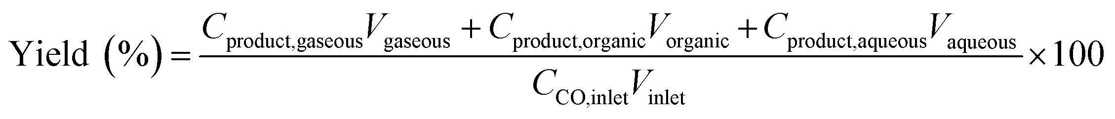
Fig. 1 shows the bulk crystalline structures of the Na0.2/Fe1Zn1.2Ox catalysts before and after 50 h of the reaction. The calcined Na0.2/Fe1Zn1.2Ox catalysts exhibited distinct XRD peaks associated with ZnFe2O4 (JCPDS no. 73-1963) and ZnO (JCPDS no. 79-2205) crystallites (Fig. 1A). The Na0.2/Fe1Zn1.2Ox catalyst increased its primary crystallites of ZnFe2O4 and ZnO when the calcination temperature of pure Fe1Zn1.2Ox was increased (Table 1). As shown in Fig. 1B, the ZnFe2O4 underwent phase transformation into Fe5C2 and ZnO during the FTS in syngas (H2/CO = 2.7). Ma et al. conducted an XRD Rietveld analysis of ZnFe2O4, which confirmed that the pure ZnFe2O4 was converted to ZnO and Fe oxides below 350 °C under reduction conditions.39 Liang et al. also reported that pure ZnFe2O4 is more easily reduced than α-Fe2O3 by comparing the activation energy and the pre-exponential factor obtained from H2-TPR.40 Interestingly, the spent catalysts, which were formed as a result of the calcination of pure Fe1Zn1.2Ox at 350 and 400 °C, exhibited an XRD pattern corresponding to crystals of ZnFe2O4 and Fe3O4 (JCPDS no. 89-691), respectively. This is attributed to the interaction between Na and ZnFe2O4, which retards the reducibility of iron species by weakening the H2 adsorption sites on the Fe oxide surface.28 Our XRD results support that smaller ZnFe2O4, which interact with Na, is relatively less able to convert Fe3O4 and ZnO. The size of Fe5C2 crystals in the spent catalysts, which was almost the same as that of ZnFe2O4 for the fresh catalysts (Table 1), increased as the temperature at which pure Fe1Zn1.2Ox underwent calcination increased. The size of the ZnO crystals was larger than that of Fe5C2 in the spent catalysts but a pattern similar to that of Fe5C2 was observed with the calcination temperature of pure Fe1Zn1.2Ox.
 | ||
| Fig. 1 XRD patterns of (a) Na0.2/Fe1Zn1.2Ox (350), (b) Na0.2/Fe1Zn1.2Ox (400), (c) Na0.2/Fe1Zn1.2Ox (500), (d) Na0.2/Fe1Zn1.2Ox (600), (e) Na0.2/Fe1Zn1.2Ox (700) before (A) and after the reaction (B) with the characteristic peaks of ZnFe2O4 (○), ZnO (△), Fe5C2 (□) and Fe3O4 (▽). | ||
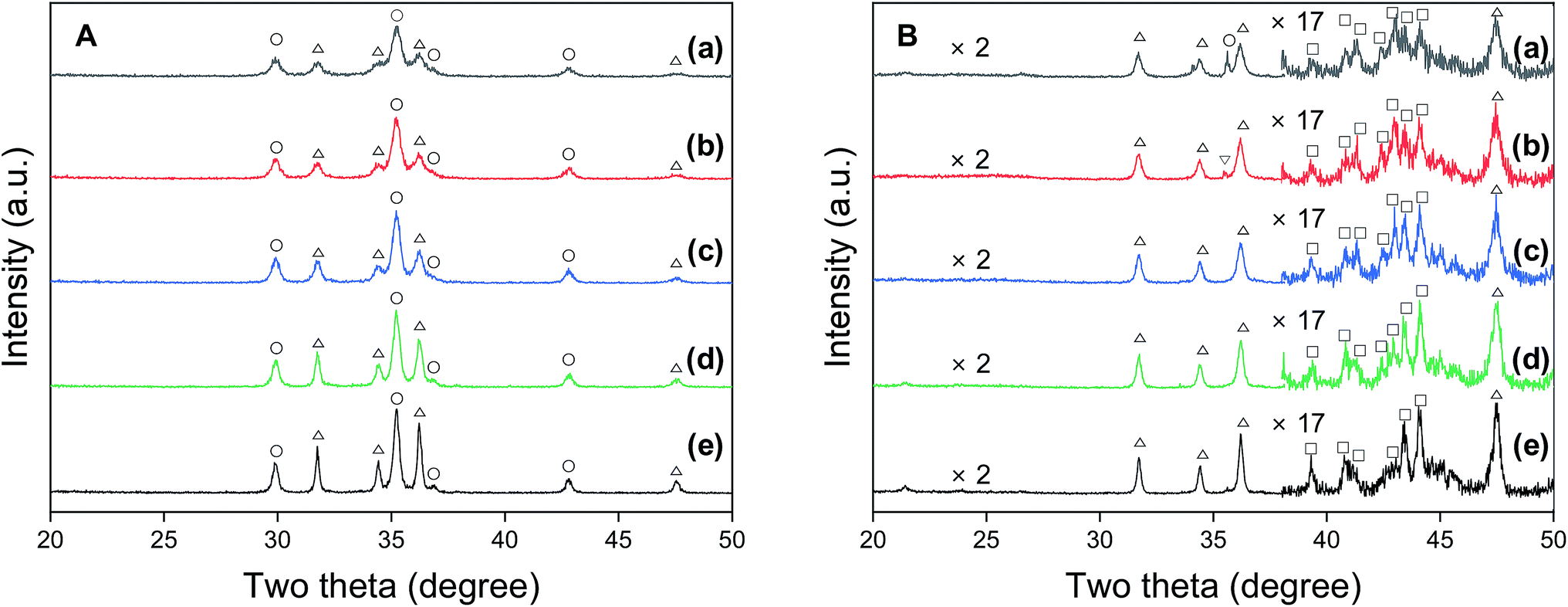
Carbon dioxide TPD shows the change in the surface basicity of the Na0.2/Fe1Zn1.2Ox catalysts, as shown in Fig. 2. The surface basicity depends on the dispersion of Na2O over the catalyst surface.41 We have found that the surface acidity can be neglected by measuring the NH3-TPD, and most Na is present as Na2O before the reaction (Fig. S1†). The catalysts showed two desorption peaks in two temperature regions: weak type (LT) and moderate type (MT). The TPD peaks for LT and MT correspond to CO2 adsorption by surface hydroxide radical and Lewis acid–base pairings, respectively.42,43 These TPD peaks occurred in similar positions for all the catalysts except for Na0.2/Fe1Zn1.2Ox (700), in which case both TPD peaks shifted to lower temperatures. Based on the deconvolution, the ratio of MT to LT increased 1.9 times when the calcination temperature of pure Fe1Zn1.2Ox was increased from 350 and 600 °C, indicating that the strength of basic sites had increased (Table 1). The catalysts maintained their large overall amount of basic sites until the calcination temperature of pure Fe1Zn1.2Ox reached 500 °C, above which the number of basic sites of the catalysts decreased by almost three times with a further increase in temperature.
 | ||
| Fig. 2 CO2-TPD patterns of (a) Na0.2/Fe1Zn1.2Ox (350), (b) Na0.2/Fe1Zn1.2Ox (400), (c) Na0.2/Fe1Zn1.2Ox (500), (d) Na0.2/Fe1Zn1.2Ox (600), (e) Na0.2/Fe1Zn1.2Ox (700). | ||
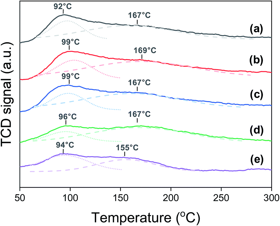
Fig. 3 shows the H2-TPR profiles of the Na0.2/Fe1Zn1.2Ox catalysts. The Fe species, in general, undergo a two-step reduction from 240 °C to 600 °C, i.e., Fe3+ → Fe2+·Fe3+ → Fe2+.28,44 The Na0.2/Fe1Zn1.2Ox (350) showed four TPR peaks, and the ratio of H2 consumption of the peaks below 403 °C to those above 403 °C was two, based on deconvolution. The H2 consumption ratio between these two temperature regions was almost independent of the particular catalyst. This indicated a two-stage reduction of the iron species of the catalysts. The partially reduced Fe species were then further reduced to α-Fe above 600 °C.44 The TPR peaks of the catalysts shifted to higher temperatures as the calcination temperature of pure Fe1Zn1.2Ox increased. Magnetic measurements by Sai et al. suggest that the magnetic properties of ZnFe2O4 were influenced by the size of its crystallites.45 Note that the oxide species of smaller iron particles are easier to reduce than those of their larger counterparts.23,46 After reducing the catalysts at 350 °C, the dispersion of iron derived from the CO-TPD results at −70 °C decreased in the following order: Na0.2/Fe1Zn1.2Ox (500) > Na0.2/Fe1Zn1.2Ox (350) > Na0.2/Fe1Zn1.2Ox (400) ∼ Na0.2/Fe1Zn1.2Ox (600) ∼ Na0.2/Fe1Zn1.2Ox (700) (Table 1).
 | ||
| Fig. 3 H2-TPR patterns of (a) Na0.2/Fe1Zn1.2Ox (350), (b) Na0.2/Fe1Zn1.2Ox (400), (c) Na0.2/Fe1Zn1.2Ox (500), (d) Na0.2/Fe1Zn1.2Ox (600), (e) Na0.2/Fe1Zn1.2Ox (700) before the reaction. | ||
3.2. Reaction measurement with Na0.2/Fe1Zn1.2Ox catalysts
The FTS was carried out at 340 °C and 2.0 MPa over the Na0.2/Fe1Zn1.2Ox catalysts, as shown in Fig. 4. Under these reaction conditions, the catalysts pre-reduced at 350 °C readily converted their iron species to iron carbides to increase CO conversion.47 The difference in the induction period required to achieve maximum CO conversion with the catalyst is probably due to the surface interaction between Na and metallic Fe species, which accelerates the formation of iron carbide species (i.e., Fe5C2).48 The catalysts maintained their high dispersion of Na until the calcination temperature of pure Fe1Zn1.2Ox was reached at 500 °C, which resulted in shorter induction periods than other catalysts (Table 1 and Fig. 4). These results indicate that Na delays the reduction of Fe1Zn1.2Ox, but promotes the activation of active site formation during the reaction, in line with the observation of Zhai et al.28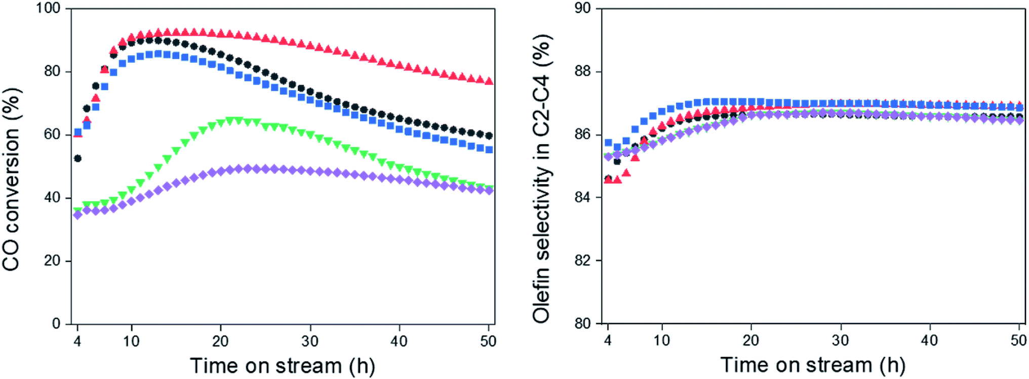 | ||
| Fig. 4 CO conversion and olefin selectivity in C2–C4, (●) Na0.2/Fe1Zn1.2Ox (350), (▲) Na0.2/Fe1Zn1.2Ox (400), (■) Na0.2/Fe1Zn1.2Ox (500), (▼) Na0.2/Fe1Zn1.2Ox (600), (◆) Na0.2/Fe1Zn1.2Ox (700). | ||
The olefin selectivity of C2–C4 hydrocarbons increased up to 20 h on stream and then remained constant regardless of the ability of the catalysts to catalyze CO conversion (Fig. 4). The induction periods for olefin selectivity in C2–C4 hydrocarbons are longer than for CO conversion with the catalysts. This indicates that the Fe5C2 species are stabilized with Na species under the reaction conditions. In this regard, the Na0.2/Fe1Zn1.2Ox (500) seemed to be superior to the other catalysts in terms of the period required to activate the active sites for olefin production.
The maximum CO conversion initially increased before decreasing again as the crystalline size of ZnFe2O4 decreased, and the maximum conversion value was obtained for the Na0.2/Fe1Zn1.2Ox (400), as shown in Fig. 5. The size of ZnFe2O4 crystals only decreased from 23.1 nm to 21.7 nm, indicating that the concentration of the total number of basic sites on the surface of the catalysts (based on the surface area) decreased by 31%. Oschatz et al. investigated the effect of a sodium/sulfur promoter with carbon-supported Fe catalysts and found that a high concentration of Na species on the surface can physically block the available iron carbide species.48 This might be the reason why the Na0.2/Fe1Zn1.2Ox (500) had a lower maximum CO conversion than Na0.2/Fe1Zn1.2Ox (400), even though these catalysts had a similar amount of basic sites (Fig. 5 and Table 1). The high ratio of Na to Fe exposed on the surface probably affects olefin production; for instance, the Na0.2/Fe1Zn1.2Ox (500) required a shorter induction period to produce light olefins than other catalysts (Fig. 4 and 5). The Na0.2/Fe1Zn1.2Ox (700) showed the lowest maximum CO conversion even with a similar concentration of basic sites on the surface (based on the surface area) compared to Na0.2/Fe1Zn1.2Ox (400) owing to its large crystalline size of ZnFe2O4. The calcination of pure Fe1Zn1.2Ox at 400 °C induces the highest number of active Fe species intimately interacted with Na species on the catalyst compared to other calcination temperatures.
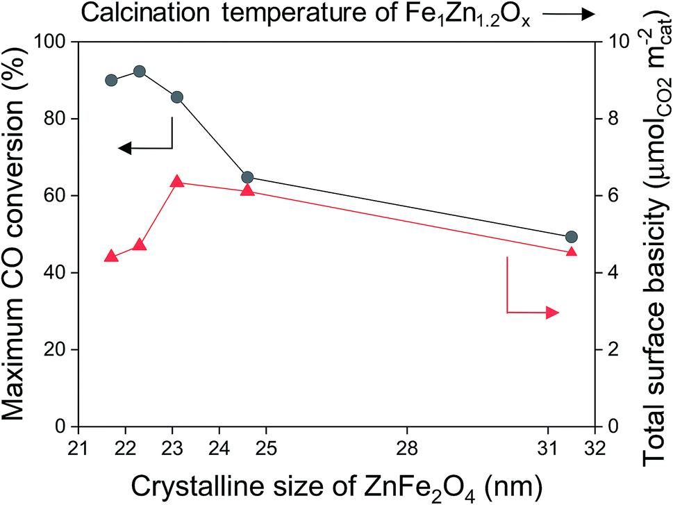 | ||
| Fig. 5 Maximum CO conversion (●) and surface basicity (▲) as a function of crystalline size of ZnFe2O4. | ||
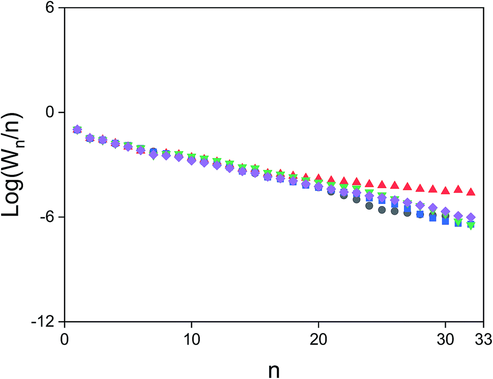
Table 2 summarizes the FTS results for the Na0.2/Fe1Zn1.2Ox catalysts. The CO conversion of Na0.2/Fe1Zn1.2Ox (400) at 50 h was 1.3–1.8 times higher than that of the other catalysts. Compared to other Fe based catalysts reported under similar reaction conditions, the Na0.2/Fe1Zn1.2Ox (400) showed comparable activity for CO conversion and olefin selectivity of C2–C4 hydrocarbons (Table S1†). We found that the size of Fe5C2 crystals of the spent catalysts tended to be inversely proportional to CO conversion at 50 h (Tables 1 and 2). Previous experimental work showed that FTS activity closely depends on the particle size of the active iron species.23,46,49 In this work, the size of the Fe5C2 crystals strongly depended on that of ZnFe2O4 for the catalysts. When the pure Fe1Zn1.2Ox was calcined at 400 °C or lower, the crystalline size of Fe5C2 for the spent catalysts became smaller than that of ZnFe2O4 of the fresh catalysts (Table 1). This means that smaller ZnFe2O4 crystals are preferable for the formation of smaller Fe5C2 crystals for Na-promoted catalysts. On the other hand, the size of ZnO crystals increased by 19.2–80.9% for 50 h of the reaction, except for the Na0.2/Fe1Zn1.2Ox (700) (Tables 1 and 2). The difference in the size of ZnO crystals before and after the reaction increased as the crystalline size of Fe5C2 decreased for the catalysts. Iglesia and co-workers investigated the effect of Zn on Fe2O3–Zn–K–Cu catalysts, and found that Zn, present as ZnFe2O4, inhibits the sintering of the Fe oxide phases during thermal treatment and activation in syngas.20 The ZnO crystals of fresh Na0.2/Fe1Zn1.2Ox (700) were the largest and had a relatively high stability in terms of ZnO crystallites during the reaction.
| Catalysts | CO conversion (%) | CO2 selectivity (%) | Hydrocarbon distribution (%) | Oxygenate selectivity (%) | α | |||
|---|---|---|---|---|---|---|---|---|
| CH4 | C2![[double bond, length as m-dash]](https://www.rsc.org/images/entities/char_e001.gif) –C4 –C4 |
C20–C40 | C5+ | |||||
a Reaction conditions: feedstock composition = 24% CO, 64% H2, 8% CO2 and 4% Ar, WHSV = 36![[thin space (1/6-em)]](https://www.rsc.org/images/entities/char_2009.gif) 000 mL gcat−1 h−1, Ptotal = 2.0 MPa, T = 340 °C. The data were obtained at 50 h. 000 mL gcat−1 h−1, Ptotal = 2.0 MPa, T = 340 °C. The data were obtained at 50 h. |
||||||||
| Na0.2/Fe1Zn1.2Ox (350) | 59.7 | 36.9 | 16.9 | 30.3 | 4.6 | 48.2 | 4.1 | 0.7 |
| Na0.2/Fe1Zn1.2Ox (400) | 76.7 | 31.6 | 15.4 | 29.2 | 4.3 | 51.1 | 3.6 | 0.8 |
| Na0.2/Fe1Zn1.2Ox (500) | 55.4 | 33.8 | 16.1 | 30.1 | 4.4 | 49.4 | 4.8 | 0.7 |
| Na0.2/Fe1Zn1.2Ox (600) | 43.1 | 28.7 | 15.9 | 27.2 | 4.1 | 52.8 | 3.2 | 0.7 |
| Na0.2/Fe1Zn1.2Ox (700) | 42.3 | 37.5 | 18.7 | 32.9 | 4.7 | 43.7 | 3.3 | 0.7 |
The selectivity for CO2 and oxygenates was statistically similar between the catalysts (Table 2). The oxygenates mainly include C1–C3 alcohols under the reaction conditions. Varying the calcination temperature of pure Fe1Zn1.2Ox did not change the molar carbon distribution of C1–C4 hydrocarbons, but for C5+ hydrocarbons, this changed, as shown in Fig. 6. The hydrocarbon distribution shows that the catalysts had a substantially similar reaction pathway to the primary products. The selectivity of Na0.2/Fe1Zn1.2Ox (400) to form C23–C32 hydrocarbons was 4.8–21.9 times higher than that of the other catalysts. Based on the Anderson–Schultz–Flory model,50 the chain growth probability (α) of Na0.2/Fe1Zn1.2Ox (400) was calculated to be 0.8, a value that was relatively higher than that of the other catalysts (0.7). Except for C3H6, the selectivity for C1–C4 hydrocarbons remained almost constant during the 50 h reaction period once the catalyst was activated (Fig. S2†). The catalysts, however, increased the CO2 selectivity by 1.5–18.6% over 20–50 h, which might be due to the partial oxidation of active iron carbide species (Fig. S2†). The results of previous studies21,22 indicated that Fe3O4, reversibly produced from oxidation by H2O, is the active site at which CO reacts with H2O to produce CO2 via the water–gas shift reaction.
 | ||
| Fig. 6 Hydrocarbon molecular weight distribution for Na/Fe–Zn catalysts, (●) Na0.2/Fe1Zn1.2Ox (350), (▲) Na0.2/Fe1Zn1.2Ox (400), (■) Na0.2/Fe1Zn1.2Ox (500), (▼) Na0.2/Fe1Zn1.2Ox (600), (◆) Na0.2/Fe1Zn1.2Ox (700). | ||
The maximum CO conversion decreased with time on stream over the catalysts, as shown in Fig. 4. Venter and co-workers performed the FTS with carbon supported K–Fe–Mn catalysts and attributed the decrease in CO conversion mainly to the carbonaceous species deposited on the iron clusters.26 Most of the carbon species on the catalytic surface are derived from different forms of coke such as graphite, fibrils, or filaments,51 the contents of which are strongly related to the catalytic activity based on the TGA results in the presence of oxygen (Fig. 4 and S3†). The amount of carbon deposited on the spent catalysts decreased in the following order: Na0.2/Fe1Zn1.2Ox (400) > Na0.2/Fe1Zn1.2Ox (500) > Na0.2/Fe1Zn1.2Ox (350) > Na0.2/Fe1Zn1.2Ox (600) > Na0.2/Fe1Zn1.2Ox (700) (Table 1). Although the Na0.2/Fe1Zn1.2Ox (400) caused the highest amount of carbon deposition during the 50 h reaction, its activity and stability are superior to those of the other catalysts. For instance, the stability of Na0.2/Fe1Zn1.2Ox (700) was similar to that of Na0.2/Fe1Zn1.2Ox (400), but its activity was 0.4–0.6 times lower. The former of these two catalysts experienced 1.5 times less coke deposition than the latter catalyst during 50 h of the reaction (Table 1). These results suggest that the Na0.2/Fe1Zn1.2Ox (400) may have a more active surface and be more mechanically stable during coke deposition than the other catalysts. Liu et al. directly visualized the evolution of Fe3O4 nanoparticles using environmental transmission electron microscopy under FTS conditions and found the surface graphitic coke to induce the breakage of the nanoparticles into smaller fragments, thereby reducing the active surface.52 On the other hand, the coke physically deposited on the catalysts did not influence the olefin selectivity of C2–C4 hydrocarbons over time. Choi et al. used X-ray photoelectron spectroscopy and X-ray adsorption near edge structure spectra to demonstrate that only 0.08 wt% Na (Na to Fe ratio = 0.01), well dispersed on the surface, is sufficient to promote the formation of iron carbide on the spinel zinc ferrite under CO2-FTS conditions at 340 °C.35 This indicates that the interaction between Fe5C2 and Na species did not change, but over time, the coke species decreased the number of active sites.
The calcination of pure Fe1Zn1.2Ox at 350 and 400 °C slightly changed the catalytic properties such as the crystallinity and surface basicity, but it considerably influenced the catalyst stability during the reaction (Table 1 and Fig. 4). The amount of carbon deposited on the spent Na0.2/Fe1Zn1.2Ox (400) was 1.3 times higher than that on the spent Na0.2/Fe1Zn1.2Ox (350). Both spent catalysts had similar BET surface areas (SBET = ∼5 m2 gcat.−1). The FTS results show that the CO2 selectivity of Na0.2/Fe1Zn1.2Ox (350) was 7.9–20.0% higher than that of Na0.2/Fe1Zn1.2Ox (400) during the 50 h reaction (Fig. S2†). The difference in the CO2 selectivity between these catalysts increased with time on stream, indicating that the former catalyst is more likely to form oxides adjacent to the iron particle than the latter catalyst under the reaction conditions. On the other hand, the Na0.2/Fe1Zn1.2Ox (350) gradually lost maximum C3H6 selectivity with time on stream. Since the Fe carbides undergo partial oxidation at the outer surface, if the Na species are not in close proximity to the Fe carbides, the charge transfer from Na ions to the iron carbides on the oxidized surface can be progressively limited.28 The CO2-TPD results before and after 30 and 50 h of the reaction indicated that both catalysts gradually lost their basic sites and consequently the residual amount of basic sites was higher in the Na0.2/Fe1Zn1.2Ox (400) than in the Na0.2/Fe1Zn1.2Ox (350), as shown in Fig. S4.† These results suggest that calcination of pure Fe1Zn1.2Ox at 400 °C is sufficient to sustain the surface Na species interacting with Fe5C2, explaining its higher FTS activity with stability compared to that at 350 °C. Therefore, we suggest that the improved catalytic performance of Na0.2/Fe1Zn1.2Ox (400) could be attributed to intimate contact between active Fe and Na species.
3.3. Linear α-olefin production with Na0.2/Fe1Zn1.2Ox catalysts
The hydrocarbon distribution of FTS at 50 h is shown in Fig. 7. The hydrocarbon products include CH4, C2–C32 paraffins, and C2–C32 olefins produced during the reaction. We grouped the products into five major categories, according to whether they were linear or branched hydrocarbons. The hydrocarbon yields were strongly related to the calcination temperature of Fe1Zn1.2Ox for the catalysts. The maximum hydrocarbon yield of Na0.2/Fe1Zn1.2Ox (400) was 49.7%, 1.4–1.9 times higher than for the other catalysts. In terms of the hydrocarbon distribution, 15.4–18.1% of the carbon was methane, which increased with increasing calcination temperature of Fe1Zn1.2Ox for the catalysts. This might be due to the CO hydrogenation, which is inhibited by the interaction of Na species with Fe carbides.48 For the C2+ hydrocarbon products, olefins (linear and branched olefin) were the main products. The selectivity for olefins increased from 58.5% to 61.3% as the calcination temperature of Fe1Zn1.2Ox increased from 350 °C to 400 °C and then decreased to 55.2% with a further increase in temperature. The selectivity for paraffins (linear and branched paraffin) showed the opposite tendency to the selectivity for olefins. The ratio of olefin to paraffin selectivity increased from 2.4 to 2.6 as the calcination temperature of Fe1Zn1.2Ox increased from 350 °C to 400 °C and then decreased to 2.1 with a further increase in temperature. The selectivity for linear paraffins was 5.8–7.2 times lower than that for linear olefins for all the catalysts. We measured the α-olefin content of hydrocarbons of the products with a different number of carbon atoms, as shown in Fig. S5.† The α-olefin content of the products initially increased before decreasing again as the number of carbon atoms in the products increased, with the maximum value obtained for the C3 products. The α-olefin content of the products then decreased until the number of carbon atoms in the products reached C8, after which the content remained the same regardless of further increases. Previous studies reported that the decrease in the olefin fraction with increasing chain length is probably the result of olefin re-adsorption because of different solubility,53 transport limitation,54 and competitive physisorption.55 We measured the chain growth probability for olefins and paraffins for each catalyst and the two values were similar (data not shown). This means that the reaction proceeds by way of a surface carbide mechanism, in which monomeric CHx species are inserted and assembled to produce olefins and paraffins.4 This mechanism mainly leads to the production of linear species. Carbon intermediates undergo chain termination via either β-hydrogen abstraction or H-addition to produce α-olefins or paraffins, respectively.29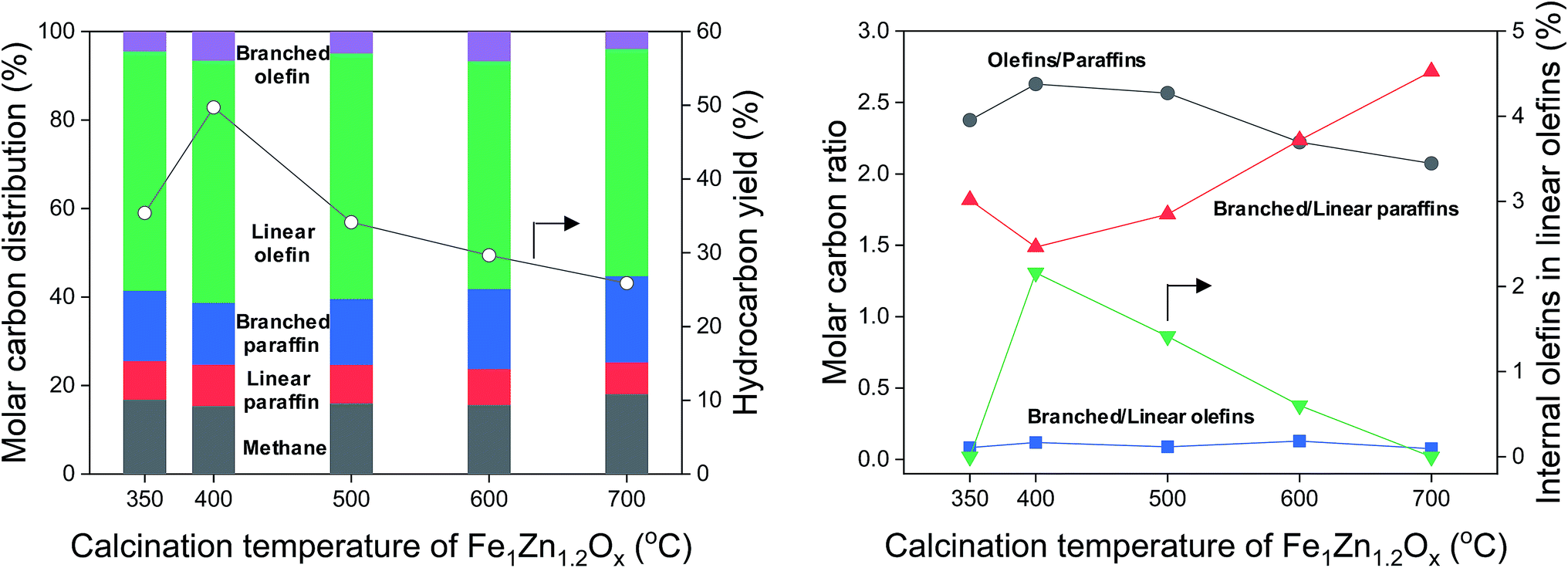 | ||
| Fig. 7 Hydrocarbon distribution, hydrocarbon yield, and molar carbon ratio for various calcination temperatures of Fe1Zn1.2Ox for the Na/Fe–Zn catalysts. | ||
In general, α-olefins are primary products that can undergo secondary reactions. Except for methane, the selectivity for hydrocarbon products decreased in the following order: linear olefins > branched paraffins > linear paraffins > branched olefins (Fig. 7). The linear olefins included α-olefins and internal olefins. The selectivity for branched paraffins was 2.6–3.9 times lower than that for linear olefins. Interestingly, the ratio of branched to linear paraffins increased from 1.5 to 2.7 as the selectivity for olefins decreased from 61.3% to 55.2%. The selectivity for branched olefins was 3.9–6.6% but did not show any tendency with different catalysts. The content of internal olefins in linear olefins increased from 0% to 2.2% as the calcination temperature of Fe1Zn1.2Ox increased from 350 °C to 400 °C, after which it decreased to 0% with a further increase in temperature. These results indicated that α-olefins are probably converted to branched paraffins over the Na0.2/Fe1Zn1.2Ox catalysts.
Fig. 8 shows the proposed secondary reaction pathways for Na-promoted catalysts. This pathway involves several reactions including (1) isomerization, (2) skeletal isomerization, (3) hydrogen transfer, and (4) hydrogenation. Given the reaction conditions, product analysis confirmed that the catalysts are unlikely to convert the products via the cracking reaction. Normal paraffins are probably inactive toward secondary reactions under FTS conditions.55 Alpha-olefins underwent double-bond isomerization to form internal olefins. This transformation can proceed through the half-hydrogenated corresponding intermediate based on isotope experiments using the K-promoted Fe–Si catalyst reported by Shi et al.56 They suggested that the metal-adsorbed hydrogen species play an important role in isomerization based on the metal-hydrogen atom addition–elimination mechanism.56 Noumi et al. investigated the isomerization of 1-butene and found that solid bases (i.e., sodium oxide and potassium oxide) were also active in the production of 2-butenes, and that the stereoselectivity was highly dependent on the reaction temperature.57 Then, the internal olefins underwent skeletal isomerization to form branched olefins. The skeletal isomerization reactions may be dominantly catalyzed by acidic sites.9,11 The possibility exists for the formation of Lewis acid sites on the catalyst after CO adsorption on unreduced iron oxides.58 Sodium cations (Na+) also act as Lewis sites that enhance (skeletal) isomerization.59,60 The isomerization products underwent further methyl and hydride shift, thus forming additional olefin isomers. In the presence of Fe metallic sites,54 those olefins can convert to paraffins via hydrogenation. Ma et al.58 investigated the effect of K on the Fe–Cu–Mo/AC catalyst in the FTS and found the product distribution to be similar to that of our Na-promoted catalysts. More specifically, the addition of K (to 0.9 wt%) increased the selectivity for branched paraffins and 1-olefins, but decreased the selectivity for n-paraffins and internal olefins at least when the number of carbon atoms were 25 or less.58 Iron catalysts reportedly tend to increase the degree of branching for products as the number of carbon atoms in the products increases.61 The selectivity data illustrate that the formation of branched paraffins was favored at the calcination temperature of Fe1Zn1.2Ox in the case of all the catalysts. Sodium interacted differently with Fe1Zn1.2Ox calcined at different temperatures, resulting in a different product distribution. The conversion of α-olefins to branched paraffins under the reaction conditions is thermodynamically favorable. The Na0.2/Fe1Zn1.2Ox (400) had a relatively low consumption rate of internal olefins compared to the other catalysts. This is probably because the catalyst has a low capacity for skeletal isomerization of internal olefins and hydrogenation of branched olefins. The well-dispersed Na breaks the z2 band on the surface of iron carbide, which weakens the adsorption of olefins and consequently inhibits direct olefin hydrogenation as a secondary reaction, based on density functional theory calculations.28 The high concentration of isolated Na species exposed on the surface may lead to a decrease in linear olefin selectivity through the production of olefin isomers during the reaction. The ZnFe2O4 may be catalytically inactive during FTS.25
 | ||
| Fig. 8 Proposed secondary reaction pathways for Na-promoted catalysts. | ||
The linear α-olefin distribution of the FTS at 50 h is shown in Fig. 9 for the different catalysts. The calcination temperature of Fe1Zn1.2Ox did not seem to significantly change the α-olefin distribution for the Na-promoted catalysts. The selectivity for α-olefins in the range of C5–C12 was 36.9–41.6%, which was 0.6–0.8 times lower than the range of C2–C4. Trace amounts of α-olefins above C13 were observed in the catalysts. The yield of α-olefins was dependent on the ability of the catalysts to achieve CO conversion. The yield of α-olefins was 26.6% for the Na0.2/Fe1Zn1.2Ox (400), 27.9–50.0% higher than for the other catalysts.
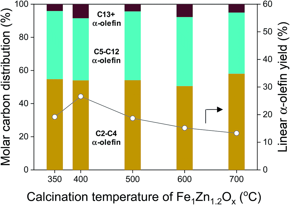 | ||
| Fig. 9 Linear α-olefin distribution and linear α-olefin yield for various calcination temperatures of Fe1Zn1.2Ox for the Na/Fe–Zn catalysts. | ||
4. Conclusion
Fischer–Tropsch synthesis was performed to selectively convert syngas (H2/CO = 2.7) into linear α-olefins over Na-promoted Fe1Zn1.2Ox catalysts at 340 °C and 2.0 MPa. A series of Fe1Zn1.2Ox catalysts was prepared at different calcination temperatures (350, 400, 500, 600, and 700 °C) and then modified with Na (2.4 wt%). Increasing the calcination temperatures of pure Fe1Zn1.2Ox increased the crystallinity, which determined the crystalline size of Fe5C2 in the catalyst during the reaction. The reducibility of Fe oxides depended on the crystallinity of Fe1Zn1.2Ox. The Na species in the catalyst slowed down the reduction of Fe1Zn1.2Ox but facilitated the formation of Fe5C2. The Na0.2/Fe1Zn1.2Ox (400) achieved maximum CO conversion, 2.5–87.2% higher than the other catalysts. Carbon chain growth on the surface of Na0.2/Fe1Zn1.2Ox (400) was superior in the range of C23–C32 hydrocarbons relative to the other catalysts. This is because the calcination of pure Fe1Zn1.2Ox at 400 °C resulted in Fe1Zn1.2Ox with smaller sized crystals and a lower total surface basicity based on the surface area of the corresponding catalyst. The Na0.2/Fe1Zn1.2Ox (400) had a higher number of active Fe carbides (Fe5C2) that intimately interacted with Na species compared to the other catalysts. The stability of Na0.2/Fe1Zn1.2Ox (400) in the FTS process was higher than that of the other catalysts, even though the amount of coke deposited on the catalyst was larger. The calcination temperature of Fe1Zn1.2Ox was closely related with the hydrocarbon yield. The Na0.2/Fe1Zn1.2Ox (400) showed a maximum hydrocarbon yield of 49.7% with a maximum olefin selectivity of 61.3% in the range of C1–C32. Under these reaction conditions, the Na0.2/Fe1Zn1.2Ox catalysts selectively converted α-olefins to branched paraffins with hydrocarbon selectivity of 13.9–19.5%. The Na0.2/Fe1Zn1.2Ox (400) had a relatively low consumption rate of internal olefins compared to the other catalysts, resulting in the lowest selectivity for branched paraffins. The yield of α-olefins in the range of C2–C32 was 26.6% for the Na0.2/Fe1Zn1.2Ox (400). The yield with this catalyst was 27.9–50.0% higher than with the other catalysts.Conflicts of interest
There are no conflicts to declare.Acknowledgements
This work was supported by the KRICT big project (SI1911-60) of the Korea Research Institute of Chemical Technology. This work was also supported by “Next Generation Carbon Upcycling Project” (NRF-2017M1A2A2043110) through the National Research Foundation (NRF) funded by the Ministry of Science and ICT, Republic of Korea.References
- M. Janardanarao, Ind. Eng. Chem. Res., 1990, 29, 1735–1753 CrossRef CAS.
- M. E. Dry, Catal. Today, 2002, 71, 227–241 CrossRef CAS.
- H. M. T. Galvis and K. P. de Jong, ACS Catal., 2013, 3, 2130–2149 CrossRef.
- M. E. Dry, J. Chem. Technol. Biotechnol., 2002, 77, 43–50 CrossRef CAS.
- E. Shafirovich and A. Varma, Ind. Eng. Chem. Res., 2009, 48, 7865–7875 CrossRef CAS.
- J. Skupinska, Chem. Rev., 1991, 91, 613–648 CrossRef CAS.
- S. Kamiguchi and T. Chihara, Catal. Lett., 2003, 85, 97–100 CrossRef CAS.
- M. Rouen, P. Queval, E. Borré, L. Falivene, A. Poater, M. Berthod, F. Hugues, L. Cavallo, O. Baslé, H. Olivier-Bourbigou and M. Mauduit, ACS Catal., 2016, 6, 7970–7976 CrossRef CAS.
- A. Hwang, S. Kim, G. Kwak, S. K. Kim, H.-G. Park, S. C. Kang, K.-W. Jun and Y. T. Kim, Catal. Lett., 2017, 147, 1303–1314 CrossRef.
- Y. Shaikh, K. Albahily, M. Sutcliffe, V. Fomitcheva, S. Gambarotta, I. Korobkov and R. Duchateau, Angew. Chem., Int. Ed., 2012, 51, 1366–1369 CrossRef CAS PubMed.
- Y. T. Kim, J. P. Chada, Z. Xu, Y. J. Pagan-Torres, D. C. Rosenfeld, W. L. Winniford, E. Schmidt and G. W. Huber, J. Catal., 2015, 323, 33–44 CrossRef CAS.
- J. A. Martens, W. H. Verrelst, G. M. Mathys, S. H. Brown and P. A. Jacobs, Angew. Chem., Int. Ed., 2005, 44, 5687–5690 CrossRef CAS PubMed.
- B. C. Enger and A. Holmen, Catal. Rev., 2012, 54, 437–488 CrossRef CAS.
- E. Iglesia, Appl. Catal., A, 1997, 161, 59–78 CrossRef CAS.
- A. Y. Khodakov, W. Chu and P. Fongarland, Chem. Rev., 2007, 107, 1692–1744 CrossRef CAS PubMed.
- F. Diehl and A. Y. Khodakov, Oil Gas Sci. Technol., 2008, 64, 11–24 CrossRef.
- D. L. King, J. Catal., 1978, 51, 386–397 CrossRef CAS.
- J. Kang, K. Cheng, L. Zhang, Q. Zhang, J. Ding, W. Hua, Y. Lou, Q. Zhai and Y. Wang, Angew. Chem., Int. Ed., 2011, 50, 5200–5203 CrossRef CAS PubMed.
- W. Ngantsoue-Hoc, Y. Zhang, R. J. O'Brien, M. Luo and B. H. Davis, Appl. Catal., A, 2002, 236, 77–89 CrossRef CAS.
- S. Li, A. Li, S. Krishnamoorthy and E. Iglesia, Catal. Lett., 2001, 77, 197–205 CrossRef CAS.
- R. J. Madon and W. F. Taylor, J. Catal., 1981, 69, 32–43 CrossRef CAS.
- D. B. Bukur, D. Mukesh and S. A. Patel, Ind. Eng. Chem. Res., 1990, 29, 194–204 CrossRef CAS.
- H. M. T. Galvis, J. H. Bitter, T. Davidian, M. Ruitenbeek, A. I. Dugulan and K. P. de Jong, J. Am. Chem. Soc., 2012, 134, 16207–16215 CrossRef PubMed.
- H. Wang, Y. Yang, J. Xu, H. Wang, M. Ding and Y. Li, J. Mol. Catal. A: Chem., 2010, 326, 29–40 CrossRef CAS.
- L. Falbo, M. Martinelli, C. G. Visconti, L. Lietti, P. Forzatti, C. Bassano and P. Deiana, Ind. Eng. Chem. Res., 2017, 56, 13146–13156 CrossRef CAS.
- J. Venter, M. Kaminsky, G. L. Geoffroy and M. A. Vannice, J. Catal., 1987, 105, 155–162 CrossRef CAS.
- J. Zhang, S. Lu, X. Su, S. Fan, Q. Ma and T. Zhao, J. CO2 Util., 2015, 12, 95–100 CrossRef CAS.
- P. Zhai, C. Xu, R. Gao, X. Liu, M. Li, W. Li, X. Fu, C. Jia, J. Xie, M. Zhao, X. Wang, Y. W. Li, Q. Zhang, X. D. Wen and D. Ma, Angew. Chem., Int. Ed., 2016, 55, 9902–9907 CrossRef CAS PubMed.
- S. L. Soled, E. Iglesia, S. M. Miseo, B. A. DeRites and R. A. Fiato, Top. Catal., 1995, 2, 193–205 CrossRef CAS.
- J.-B. Li, H.-F. Ma, H.-T. Zhang, Q.-W. Sun, W.-Y. Ying and D.-Y. Fang, Fuel Process. Technol., 2014, 125, 119–124 CrossRef CAS.
- M. C. Ribeiro, G. Jacobs, B. H. Davis, D. C. Cronauer, A. J. Kropf and C. L. Marshall, J. Phys. Chem. C, 2010, 114, 7895–7903 CrossRef CAS.
- K. Cheng, V. V. Ordomsky, B. Legras, M. Virginie, S. Paul, Y. Wang and A. Y. Khodakov, Appl. Catal., A, 2015, 502, 204–214 CrossRef CAS.
- M. E. Dry and G. J. Oosthuizen, J. Catal., 1968, 11, 18–24 CrossRef CAS.
- X. An, B. S. Wu, H. J. Wan, T. Z. Li, Z. C. Tao, H. W. Xiang and Y. W. Li, Catal. Commun., 2007, 8, 1957–1962 CrossRef CAS.
- Y. H. Choi, E. C. Ra, E. H. Kim, K. Y. Kim, Y. J. Jang, K. N. Kang, S. H. Choi, J. H. Jang and J. S. Lee, ChemSusChem, 2017, 10, 4764–4770 CrossRef CAS PubMed.
- B. Zhao, P. Zhai, P. Wang, J. Li, T. Li, M. Peng, M. Zhao, G. Hu, Y. Yang, Y.-W. Li, Q. Zhang, W. Fan and D. Ma, Chem, 2017, 3, 323–333 CAS.
- H. M. T. Galvis, A. C. J. Koeken, J. H. Bitter, T. Davidian, M. Ruitenbeek, A. I. Dugulan and K. P. de Jong, J. Catal., 2013, 303, 22–30 CrossRef.
- H. Ni, C. S. Hsu, C. Ma, Q. Shi and C. Xu, Energy Fuels, 2013, 27, 5069–5075 CrossRef CAS.
- L. Ma, R. Wu, H. Liu, W. Xu, L. Chen and S. Chen, Solid State Sci., 2011, 13, 2172–2176 CrossRef CAS.
- M. Liang, W. Kang and K. Xie, J. Nat. Gas Chem., 2009, 18, 110–113 CrossRef CAS.
- J. Wei, J. Sun, Z. Wen, C. Fang, Q. Ge and H. Xu, Catal. Sci. Technol., 2016, 6, 4786–4793 RSC.
- C.-H. Zhang, Y. Yang, B.-T. Teng, T.-Z. Li, H.-Y. Zheng, H.-W. Xiang and Y.-W. Li, J. Catal., 2006, 237, 405–415 CrossRef CAS.
- A. A. Ibrahim, A. A. Al-Fatesh, H. Atia, A. H. Fakeeha, S. O. Kasim and A. E. Abasaeed, Int. J. Energy Res., 2018, 42, 4120–4130 CrossRef CAS.
- K. Cheng, M. Virginie, V. V. Ordomsky, C. Cordier, P. A. Chernavskii, M. I. Ivantsov, S. Paul, Y. Wang and A. Y. Khodakov, J. Catal., 2015, 328, 139–150 CrossRef CAS.
- R. Sai, S. D. Kulkarni, S. S. M. Bhat, N. G. Sundaram, N. Bhat and S. A. Shivashankar, RSC Adv., 2015, 5, 10267–10274 RSC.
- P. A. Chernavskii, V. O. Kazak, G. V. Pankina, V. V. Ordomsky and A. Y. Khodakov, ChemCatChem, 2016, 8, 390–395 CrossRef CAS.
- J. Zhang, M. Abbas and J. Chen, Catal. Sci. Technol., 2017, 7, 3626–3636 RSC.
- M. Oschatz, N. Krans, J. Xie and K. P. de Jong, J. Energy Chem., 2016, 25, 985–993 CrossRef.
- J.-X. Liu, P. Wang, W. Xu and E. J. M. Hensen, Engineering, 2017, 3, 467–476 CrossRef.
- P. J. Flory, J. Am. Chem. Soc., 1936, 58, 1877–1885 CrossRef CAS.
- H. M. T. Galvis, J. H. Bitter, C. B. B. Khare, M. Ruitenbeek, A. I. Dugulan and K. P. de Jong, Science, 2012, 335, 835–838 CrossRef PubMed.
- X. Liu, C. Zhang, Y. Li, J. W. Niemantsverdriet, J. B. Wagner and T. W. Hansen, ACS Catal., 2017, 7, 4867–4875 CrossRef CAS.
- L.-M. Tau, H. A. Dabbagh and B. H. Davis, Energy Fuels, 1990, 4, 94–99 CrossRef CAS.
- E. Iglesia, S. C. Reyes and R. J. Madon, J. Catal., 1991, 129, 238–256 CrossRef CAS.
- E. W. Kuipers, I. H. Vinkenburg and H. Oosterbeek, J. Catal., 1995, 152, 137–146 CrossRef CAS.
- B. Shi, R. J. O'Brien, S. Bao and B. H. Davis, J. Catal., 2001, 199, 202–208 CrossRef CAS.
- H. Noumi, T. Misumi and S. Tsuchiya, Chem. Lett., 1978, 439–442 CrossRef CAS.
- W. Ma, E. L. Kugler and D. B. Dadyburjor, Energy Fuels, 2007, 21, 1832–1842 CrossRef CAS.
- B. Wichterlova, N. Zilkova, E. Uvarova, J. Cejka, P. Sarv, C. Paganini and J. A. Lercher, Appl. Catal., A, 1999, 182, 297–308 CrossRef CAS.
- E. A. Lombardo, G. A. Sill and W. K. Hall, J. Catal., 1971, 22, 54–63 CrossRef.
- J. H. l. Roux and L. J. Dry, J. Appl. Chem. Biotechnol., 1972, 22, 719–726 CrossRef.
Footnote |
| † Electronic supplementary information (ESI) available. See DOI: 10.1039/c9ra02471a |
| This journal is © The Royal Society of Chemistry 2019 |