 Open Access Article
Reduced graphene oxide-supported cobalt oxide decorated N-doped graphitic carbon for efficient bifunctional oxygen electrocatalysis†
Meng Li‡
a,
Cheng Bao‡a,
Yuting Liua,
Jing Menga,
Xia Liua,
Yongliang Caia,
Delvin Wuuc,
Yun Zong c,
Teck-Peng Lohab and
Zhijuan Wang
 *a
*a
aInstitute of Advanced Synthesis (IAS), School of Chemistry and Molecular Engineering (SCME), Jiangsu National Synergetic Innovation Center for Advanced Materials (SICAM), Nanjing Tech University, 30 South Puzhu Road, Nanjing 211816, P. R. China. E-mail: ias_zjwang@njtech.edu.cn
bDivision of Chemistry and Biological Chemistry, School of Physical and Mathematical Sciences, Nanyang Technological University, Singapore 637616, Republic of Singapore
cInstitute of Materials Research and Engineering, A*STAR (Agency for Science, Technology and Research), 2 Fusionopolis Way, Innovis #08-03, Singapore 138634, Republic of Singapore
First published on 28th May 2019
Abstract
A high-performance composite bifunctional electrocatalyst for oxygen reduction reaction (ORR) and oxygen evolution reaction (OER) has been synthesized via in situ growth of a hybrid precursor of graphene oxide (GO) and cobalt-based zeolite imidazolium framework (ZIF-67) under hydrothermal condition, followed by calcination at elevated temperature. The as-prepared composite bifunctional catalyst is confirmed to possess a structure of N-GC/Co@CoO/rGO, with core–shell nanoparticles of Co@CoO encapsulated in nitrogen-doped graphitic carbon (N-GC) thin layers which are then overall supported by reduced graphene oxide (rGO) sheets. With N-GC furnishing high population of ORR active sites, CoO being active for OER which is further enhanced by a highly conductive metal core, rGO sheets enhancing the overall electronic conduction, as well as the multiple synergistic couplings in the composite materials, pronounced ORR and OER catalytic activities with superior stability have been achieved. The catalysts also showed excellent tolerance to the crossover effect to methanol, showing great potential in energy-related applications requiring efficient oxygen electrocatalysis.
1. Introduction
Electrochemical oxygen reduction reaction (ORR) and oxygen evolution reaction (OER) play critical roles in a wide range of renewable energy technologies.1 For instance, a bifunctional electrocatalyst, i.e. an electrocatalyst with high activities toward both ORR and OER is the key to a high-performance regenerative fuel cell or a rechargeable metal–air battery.2 Catalysts comprising precious metal or metal oxide mostly are only good for ORR (e.g. Pt/C) or OER (e.g. RuO2, Ir/C) catalysis.3 With the additional disadvantages of scarcity, high cost and poor stability in the alkaline electrolyte, it severely hampers their large-scale industrial applications.4 A wide range of alternate electrocatalyst with high activity, low cost and good stability are developed in the past a few years, with majority of them using a combination of metal oxides or sulfides with heteroatom-doped carbons.5,6 Nevertheless, unbalanced performance was obtained in most cases. A transition-metal-based truly bifunctional electrocatalyst with superior catalytic activities toward both ORR and OER is rare.Recently, metal–organic frameworks (MOFs), a family of crystalline porous materials with well-organized structures, were employed to fabricate porous transition metal-doped carbon materials or nanoporous carbons decorated with transition-metal or their oxide nanoparticles.7–10 The MOF structure with metal ions separated from each other by organic ligands ensures good dispersion of nanoparticles after the high-temperature calcination. In addition, their large specific surface area and choice of metal-ions and ligand make it possible to construct high-performance bifunctional electrocatalysts for OER/ORR based applications.11 Nevertheless, pristine MOF has electrical conductivity issues9 while the MOF-derived carbon often cannot survive the corrosion by strong alkaline electrolyte,12 posing challenges to be overcome for practical applications.
Reduced graphene oxide (rGO) possesses good electrical conductivity, excellent mechanical and chemical stability, ultrahigh surface area (>2600 m2 g−1), and can be easily prepared in large scale.9,12 It is hence a superior additive to the electrode to enhance the electrical conductivity, facilitate nanoparticle dispersion, and furnish the chemical stability to the composite electrode. Therefore, it is anticipated to achieve superior electrocatalytic performance from their respective advantages by combining MOFs with rGO to form a hybrid material.
Herein, a cobalt-based zeolite imidazole framework (ZIF), i.e., ZIF-67 ([Co(MeIm)2]n), and graphene oxide (GO) were chosen as the precursors to produce a new bifunctional catalyst. After hydrothermal reaction and the subsequent carbonization at elevated temperature, the composite ZIF-67/GO was converted to cobalt@cobalt oxide nanoparticles decorated nitrogen-doped nanoporous graphitic carbons (GC)13 composited with rGO sheets.14 The composite catalyst exhibited excellent electrocatalytic performances toward ORR and OER in alkaline media with superior stability.
2. Experimental section
2.1 Chemicals and materials
Natural graphite was purchased from Bay Carbon (Bay City, Michigan, USA) and used for the synthesis of graphene oxide (GO). Cobalt chloride (CoCl2, 97%, Sigma), 2-methylimidazole (MeIm, 99%, Sigma), methanol (99.8%, Sigma), Nafion 117 solution (5 wt%, Sigma), potassium hydroxide (99.9%, Sigma), sulfuric acid (H2SO4, 95–97%, Merck), 20 wt% platinum supported on Vulcan XC-72 carbon (Pt/C, E-Tek) and 20 wt% iridium on Vulcan XC-72 carbon (Ir/C, Premetek) were used as received. The aqueous solutions in this work were prepared with ultrapure water (18.2 MΩ cm, 25 °C), obtained from a Milli Q Plus water purification system (Millipore, USA).2.2 Synthesis of Co@CoO-decorated N-doped graphitic carbons (N-GC/Co@CoO)
CoCl2 (519 mg), polyvinylpyrrolidone (PVP, 600 mg) and MeIm (2630 mg) were added in sequence into 80 mL of methanol under stirring. After 12 h of reaction at room temperature, the formed purple precipitates were collected via centrifugation, washed thoroughly with methanol, and dried at 80 °C.13 The obtained bright purple powder of ZIF-67 was heated to 800 °C at a temperature ramp of 5 °C min−1 under argon flow and kept at 800 °C for 3 h, followed by maintaining in the air for several days to yield cobalt@cobalt oxide nanoparticle-decorated nitrogen-doped graphitic carbons (N-GC/Co@CoO).2.3 Synthesis of N-GC/Co@CoO/rGO composite
Graphene oxide (GO) water dispersion at a concentration of 1 wt% was synthesized following a previously reported method.15 To synthesize N-GC/Co@CoO/rGO composite, 2.0 g of such GO dispersion was mixed with 20 mL of methanol under sonication to achieve a homogeneous dispersion. A methanolic solution (10.4 mL) of CoCl2 (0.31 g) was then introduced while stirring at room temperature. After sufficient mixing, 10.4 mL methanolic solution of MeIm (1.57 g) was added dropwise. 1 h after the addition, the reaction mixture was transferred into a 100 mL autoclave to allow for another 12 h of reaction at 100 °C under hydrothermal condition. Upon cooling it down to room temperature, black solids precipitated out which were collected via centrifugation and washed thoroughly with methanol. The oven-dried black powder was heated to 800 °C at a temperature ramp of 5 °C min−1 under argon flow and kept at 800 °C for 3 h to yield the N-GC/Co/rGO composites. After the sample was stored under ambient conditions, the cobalt oxide was formed on the surface of Co nanoparticles to form N-GC/Co@CoO/rGO.7 The ratio of GO to CoCl2 and the calcination temperature (600, 700 and 900 °C) were varied to optimize the synthetic procedures. As control, N-GC/Co@CoO/rGO composites were also prepared following a simple mixing approach16 in which the pre-synthesized ZIF-67 powder13 was mixed with GO in its methanolic solution via sonication. The solid collection and post-processing just followed the same procedure described above. A further control sample was made by mixing the powders of rGO (2.0 g) and Co/GC (0.10 g) mechanically.2.4 Physical characterizations
Crystal phase structure of N-GC/Co@CoO/rGO was analyzed using a Bruker D8 advanced diffractometer with Cu Kα radiation (λ = 1.5406 Å). Its morphology and fine structure were studied on a field emission gun scanning electron microscope (FEG-SEM, JEOL JSM7600F) and a high-resolution transmission electron microscope (HR-TEM, JEOL, JSM-2100F), operating at an accelerating voltage of 5 or 200 kV, respectively. The presence of elements and their valence status in the samples were analyzed by X-ray photoelectron spectroscopy (XPS) with Al Kα radiation (VGESCALAB 200i-XL). The graphitic carbon was evidenced by Raman spectra recorded on a Renishaw inVia confocal Raman microscope with a 532 nm laser. The N2 sorption isotherms were collected on a Quantachrome Instruments Autosorb AS-6B cooled by liquid nitrogen.2.5 Electrochemical measurements
The electrochemical studies were performed on Autolab PGSTAT302N (Metrohm) using a three-electrode cell configuration. Glassy carbon electrode (GCE, Φ = 5 mm), platinum foil (Pt) and saturated calomel electrode (SCE) were the working electrode, counter electrode and reference electrode, respectively. All potentials herein were referenced to reversible hydrogen electrode (RHE) by conversions following ERHE = ESCE + 0.990 V (0.1 M KOH) or ERHE = ESCE + 1.051 V (1 M KOH). To formulate a catalyst ink, 13 mg of a respective catalyst and 65 μL of Nafion (5 wt% in H2O) were dispersed into 2.4 mL of water/isopropanol (v/v, 2.5![[thin space (1/6-em)]](https://www.rsc.org/images/entities/char_2009.gif) :
:![[thin space (1/6-em)]](https://www.rsc.org/images/entities/char_2009.gif) 1) mixture solvent via sonication. 10 μL of the ink was pipetted onto a glassy carbon rotating disk electrode (RDE) and dried in air, giving a catalyst loading of 0.25 mg cm−2. The benchmark catalyst inks of commercial Pt/C or Ir/C were prepared in a similar way, except the use of 4 mg of Pt/C or Ir/C, 13 μL of Nafion and 1 mL of the mixture solvent. With 5 μL of such ink pipetted onto a GCE, the achieved catalyst loading was 0.1 mg cm−2. The cyclic voltammograms (CV) were obtained at a scan rate of 50 mV s−1 in N2- or O2-saturated 0.1 M KOH, achieved by purging with high-purity N2 or O2 for 30 min, respectively.
1) mixture solvent via sonication. 10 μL of the ink was pipetted onto a glassy carbon rotating disk electrode (RDE) and dried in air, giving a catalyst loading of 0.25 mg cm−2. The benchmark catalyst inks of commercial Pt/C or Ir/C were prepared in a similar way, except the use of 4 mg of Pt/C or Ir/C, 13 μL of Nafion and 1 mL of the mixture solvent. With 5 μL of such ink pipetted onto a GCE, the achieved catalyst loading was 0.1 mg cm−2. The cyclic voltammograms (CV) were obtained at a scan rate of 50 mV s−1 in N2- or O2-saturated 0.1 M KOH, achieved by purging with high-purity N2 or O2 for 30 min, respectively.
In ORR tests, the electrolyte was 0.1 M KOH aqueous solution. The rotation speed was 400 to 2500 rpm with a scan rate of 5 mV s−1. The number of transferred electrons (n) per O2 molecule in the ORR and kinetic current density were calculated from the Koutecky–Levich equations.2,7 The peroxide ion content in ORR was determined by a rotating ring-disk electrode (RRDE) with an E7R9 AFE7R9GCPT tip (Pine Instruments) at a rotation speed of 1600 rpm, and the percentage of peroxide ion (HO2−), Xperoxide, is calculated by the eqn (1) below:2
 | (1) |
Liner sweep voltammograms for OER were obtained in 1 M KOH at a scan rate of 5 mV s−1 and a rotation speed of 1600 rpm. The data curves were calibrated by iR-compensation. The solution resistance was obtained by electrochemical impedance spectroscopy (EIS) technique.
To test the methanol crossover effect, the chronoamperometric response at 0.7 V was recorded in 0.1 M KOH at a rotation speed of 1600 rpm. After a stable baseline was collected in chronoamperometric response curve, 27.3 mL methanol was injected to 0.1 M KOH to reach a final concentration of 3 M methanol.
3. Results and discussion
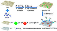
The synthesis process of N-GC/Co@CoO/rGO nanocomposite is straightforward (Scheme 1). It involves simple sonication-assisted mixing, hydrothermal treatment, and final high temperature calcination. GO with its rich carboxylic, epoxy and alkoxy groups are naturally negatively charged in aqueous media,15 accumulating Co2+ on its surface via electrostatic interaction to form a uniform GO/Co(II) composite.17–19 The addition of 2-methylimidazole (MeIm) with followed hydrothermal treatment led to the formation of a dark purple powder (Fig. S2a†), ZIF-67 crystals in rhombic dodecahedron shape supported on rGO (rGO-ZIF-67).13,14 After the calcination at 800 °C under argon flow and storage under ambient conditions,7 black power N-GC/Co@CoO/rGO nanocomposite was formed (Fig. S2b†) with Co@CoO nanoparticles anchored on N-GC that is overall supported by rGO.10,13,20The morphology and fine structure of N-GC/Co@CoO/rGO was studied using SEM, TEM and high resolution TEM (HRTEM) (Fig. 1). Uniform sub-micron-sized rhombic dodecahedron-shaped carbonized ZIF-67 particles (i.e., N-GC/Co@CoO) are seen (Fig. 1a) with rGO sheets underneath as the support layer, the same as what was illustrated in Scheme 1. An enlarged image of the rhombic dodecahedral shaped particles suggests its size as ∼1 μm (Fig. 1b), similar to that of its precursor, ZIF-67 (Fig. S3†). HRTEM image gives the detailed structure as carbon-wrapped black nanoparticles (Fig. 1c), and the lattice fringes of 0.207 nm (Fig. 1d) can be attributed to the (111) plane of Co.7 The lattice fringes of carbon layer were measured to be 0.348 nm (Fig. 1d), matching well with the (002) plane of graphitic carbon20 formed by cobalt-catalyzed carbonization process.3 Such high-conductivity carbon coating on metal/metal oxide nanoparticles improves their electric conductivity for enhanced catalytic activity.7,21
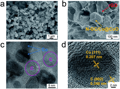 | ||
| Fig. 1 SEM images of N-GC/Co@CoO/rGO at (a) low and (b) high magnifications, (c) TEM and (d) high resolution TEM images of N-GC/Co@CoO/rGO. | ||
The chemical composition of N-GC/Co@CoO/rGO was examined by X-ray photoelectron spectroscopy (XPS). The full scan spectrum (Fig. 2a) indicated the co-existence of C, Co, N and O. The deconvolution of high-resolution C 1s spectrum gives 3 peaks for C–C (284.5 eV), C![[double bond, length as m-dash]](https://www.rsc.org/images/entities/char_e001.gif) N (285.7 eV) and C–O (287.8 eV), respectively (Fig. 2b).21 The resolved N 1s in Fig. 2c revealed pyridinic N (398.9 eV) and graphitic N (400.8 eV) as the major forms of doped nitrogen in N-GC/Co@CoO/rGO. Pyridinic N has been suggested as ORR catalytic active site,22 equipping N-GC/Co@CoO/rGO with high ORR activity. In the cobalt region (Fig. 2d), peaks at 778.3 and 793.5 eV originate from Co 2p3/2 and Co 2p1/2, respectively. The deconvoluted Co 2p spectrum has Co0, Co2+ and their shake-up (satellites) peaks (Fig. 2d).21 The peak at 778.2 eV matches the Co 2p3/2 binding energy of Co (0),7 with the one at 780.6 eV being that of Co(II) according to a previous report showing Co 2p3/2 binding energy of CoO at 780–780.9 eV.23 Likely Co2+ was produced from the oxidation of Co nanoparticles on N-GC/rGO by aerobic oxygen over extended storage under ambient conditions.7,24 Hence, the nanoparticles encapsulated in N-GC on rGO should be in Co@CoO core–shell structure, which was further investigated by the XRD and Raman spectroscopy.
N (285.7 eV) and C–O (287.8 eV), respectively (Fig. 2b).21 The resolved N 1s in Fig. 2c revealed pyridinic N (398.9 eV) and graphitic N (400.8 eV) as the major forms of doped nitrogen in N-GC/Co@CoO/rGO. Pyridinic N has been suggested as ORR catalytic active site,22 equipping N-GC/Co@CoO/rGO with high ORR activity. In the cobalt region (Fig. 2d), peaks at 778.3 and 793.5 eV originate from Co 2p3/2 and Co 2p1/2, respectively. The deconvoluted Co 2p spectrum has Co0, Co2+ and their shake-up (satellites) peaks (Fig. 2d).21 The peak at 778.2 eV matches the Co 2p3/2 binding energy of Co (0),7 with the one at 780.6 eV being that of Co(II) according to a previous report showing Co 2p3/2 binding energy of CoO at 780–780.9 eV.23 Likely Co2+ was produced from the oxidation of Co nanoparticles on N-GC/rGO by aerobic oxygen over extended storage under ambient conditions.7,24 Hence, the nanoparticles encapsulated in N-GC on rGO should be in Co@CoO core–shell structure, which was further investigated by the XRD and Raman spectroscopy.
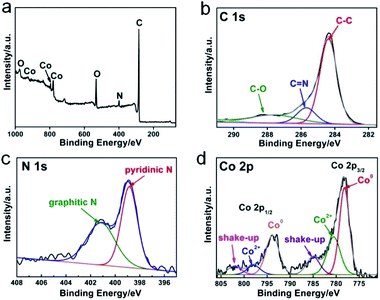 | ||
| Fig. 2 X-ray photoelectron spectroscopy (XPS) spectrum of (a) N-GC/Co@CoO/rGO, respective high-resolution and the corresponding deconvoluted spectra of (b) C 1s, (c) N 1s and (d) Co 2p. | ||
The crystal structure of N-GC/Co@CoO/rGO nanocomposite was studied by X-ray diffraction (XRD) analysis, and the pattern of peaks is shown in Fig. 3a. Clearly, Co25 and CoO2 diffraction composed of the XRD pattern of N-GC/Co@CoO/rGO nanocomposite. In detail, the peaks at 44.2° and 51.4° correspond to crystalline facets (111) and (200) of Co, suggesting the reduction of Co2+ to metallic Co during carbonization. The size of Co nanoparticles was calculated from Scherrer equation as ∼10 nm,26 similar to the one observed in TEM images (Fig. 1c). The co-existence of the diffraction peaks of CoO echoes the XPS results (Fig. 2d). Compared with the XRD pattern of N-GC/Co/rGO (Fig. S4†), CoO has been successfully formed after the sample was kept in the air for several days. The graphitic carbon in N-GC/Co@CoO/rGO composite was further confirmed by its Raman spectrum (Fig. 3b).27 The peaks at 1350 and 1582 cm−1 can be attributed to the D (disordered carbon) and G (graphitic carbon) bands, respectively. Those at 2030 and 2178 cm−1 arose from the υ(CN) scattering,28 present in both rGO-ZIF-67 and N-GC/Co@CoO/rGO. The one at 685 cm−1 appearing in N-GC/Co@CoO/rGO is from the CoO shell,29 which is in consistence with the XRD (Fig. 3a) and XPS (Fig. 2d) results. In addition, N-GC/Co@CoO/rGO showed type-IV isotherm (IUPAC definition) with a high Brunauer–Emmett–Teller (BET) specific surface area of 516 m2 g−1 (Fig. 3c). The presence of H1 hysteresis loop suggests the existence of the mesoporous feature in N-GC/Co@CoO/rGO nanocomposite.7
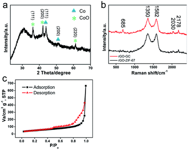 | ||
| Fig. 3 (a) XRD pattern of N-GC/Co@CoO/rGO, (b) Raman spectra of rGO-ZIF-67 and N-GC/Co@CoO/rGO, and (c) nitrogen adsorption–desorption isotherm of N-GC/Co@CoO/rGO. | ||
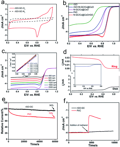
The electrocatalytic performances of N-GC/Co@CoO/rGO are shown in Fig. 4a. As anticipated, N-GC/Co@CoO/rGO gave no reduction peak in O2-depleted aqueous KOH electrolyte but a well-defined cathodic peak at 0.8 V in O2-saturated electrolyte, indicating its pronounced catalytic activity toward ORR. The variations in the content of cobalt precursor (Fig. S5a†) and the carbonization temperature (Fig. S5b†) in the synthesis, interestingly, all led to some compromise in the ORR activity (see detail in the Experimental section). The activity of N-GC/Co@CoO/rGO was also compared with control samples of rGO, N-GC/Co@CoO, rGO + N-GC/Co@CoO (mechanical mixture of rGO and N-GC/Co@CoO powders) and Pt/C under the same experimental conditions (Fig. 4b). The onset potential (Eonset) of N-GC/Co@CoO/rGO (0.99 V) is found more positive than that of rGO (0.85 V), N-GC/Co@CoO (0.92 V), rGO + N-GC/Co@CoO (0.89 V) and Pt/C (0.98 V). In addition, the half-wave potential (E1/2) of N-GC/Co@CoO/rGO is more positive than that of all these catalysts (including Pt/C), demonstrating the fast ORR kinetics of N-GC/Co@CoO/rGO. The higher ORR activity, as suggested by more positive Eonset and E1/2, is a collective result of the metallic Co cores as ORR “booster”,30 high specific surface area, the unique mesoporous hollow framework, the high electric conductivity of graphitic carbon shells,7,21,30 as well as the N-doping into GC.20 The notably higher ORR activity of N-GC/Co@CoO/rGO compared to that of rGO + N-GC/Co@CoO, a composite with similar composition made from mechanical mixing, showing the benefit of a “chemically” integrated structure which likely boosts the ORR via enhanced synergistic coupling between rGO and N-GC/Co@CoO. In addition, N-GC/Co@CoO/rGO has also notably outperformed its counterpart obtained by mixing of rGO and N-GC/Co@CoO dispersions (Fig. S5c†),16 indicating the importance of in situ growth to enable a more intact structure to facilitate high ORR activity.2
To gain insight into the electron transfer kinetics of N-GC/Co@CoO/rGO during ORR, its rotating disk voltammetry with different rotation rates (ω) was investigated (Fig. 4c). Liner sweep voltammetry (LSV) curves indicated that the current density (J) of N-GC/Co@CoO/rGO increased steadily with ω. The relationship between J−1 and ω−1/2, i.e., the Koutecky–Levich (K–L) plots (inset of Fig. 4c), were obtained from the data displayed in Fig. 4c. The good linearity and parallelism over the potential range from 0.25 to 0.75 V of these plots suggested typical first-order reaction kinetics with respect to the dissolved O2 concentration. The number of electrons (n) transferred per oxygen molecule were calculated from the slopes of the plots (inset of Fig. 4c) using K–L equation (see details in the Experimental section), showing a four-electron transfer dominated ORR process for N-GC/Co@CoO/rGO over a wide potential window of 0.25 to 0.75 V (Fig. S6†).
The ORR of N-GC/Co@CoO/rGO was further investigated in the rotating ring-disk electrode (RRDE) experiments, and a typical sweeping voltammogram at a rotation speed of 1600 rpm is shown in Fig. 4d. The yield of HO2− was found below 10% (Fig. S7†) over the potential of 0.25 to 0.75 V, giving an n value ranging from 3.79 to 3.97 (inset of Fig. 4d). This is highly consistent with the results derived from the K–L plots of RDE measurements (inset of Fig. 4c), further confirming the efficient ORR with a 4-electron transfer reaction pathway for the N-GC/Co@CoO/rGO grown via the in situ approach.
The long-term stability of N-GC/Co@CoO/rGO was evaluated by recording its chronoamperometric response for ORR. As shown in Fig. 4e, the current loss for N-GC/Co@CoO/rGO was ∼6% over 60![[thin space (1/6-em)]](https://www.rsc.org/images/entities/char_2009.gif) 000 s. In contrast, Pt/C suffered a rapid current loss at the initial stage of discharge, totaled at about 30% over the similar length of period. The rapid current loss for Pt/C is likely caused by the detachment of some Pt nanoparticles from the carbon support in alkaline medium.31 The good stability of N-GC/Co@CoO/rGO is harvested from the encapsulation of Co nanoparticles by N-doped graphitic carbon thin layers (Fig. 1c), preventing their agglomeration over time to keep the high catalytic activity.30 This is validated by the fact that the stability dropped fast in the absence of rGO support (Fig. S8†).
000 s. In contrast, Pt/C suffered a rapid current loss at the initial stage of discharge, totaled at about 30% over the similar length of period. The rapid current loss for Pt/C is likely caused by the detachment of some Pt nanoparticles from the carbon support in alkaline medium.31 The good stability of N-GC/Co@CoO/rGO is harvested from the encapsulation of Co nanoparticles by N-doped graphitic carbon thin layers (Fig. 1c), preventing their agglomeration over time to keep the high catalytic activity.30 This is validated by the fact that the stability dropped fast in the absence of rGO support (Fig. S8†).
As a potential ORR catalyst for direct methanol fuel cell (DMFC) applications, the tolerance of N-GC/Co@CoO/rGO to the crossover effect of methanol (CH3OH) was also tested and compared with that of Pt/C. With Pt/C catalyst the current density suffered a sharp decrease upon the addition of CH3OH, while no obvious change in the current density was visible when N-GC/Co@CoO/rGO was used as the catalyst in the test under similar experimental conditions (Fig. 4f). The good durability and tolerance to the crossover effect of CH3OH make N-GC/Co@CoO/rGO a promising candidate with great potential in primary Zn–air battery, fuel cell and other catalytic applications.
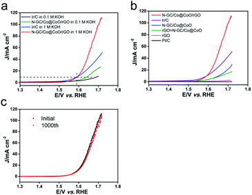
The OER performance of N-GC/Co@CoO/rGO was also studied together with a number of control samples, and the results are presented in Fig. 5. Clearly, both N-GC/Co@CoO/rGO and Ir/C showed higher anodic current density and lower onset potential in 1 M KOH than that in 0.1 M KOH (Fig. 5a). 1 M KOH was hence also chosen as electrolyte in the OER studies of all other control samples, and their LSV curves are shown in Fig. 5b. N-GC/Co@CoO/rGO presents clear advantages over all the control samples (except Ir/C) tested under similar experimental conditions. It has also notably outperformed a series of other control samples of similar composition synthesized with varied amount of cobalt precursor (Fig. S9a†) or at different carbonization temperatures (Fig. S9b†). Compared with Ir/C, N-GC/Co@CoO/rGO showed a little lower onset potential (1.53 vs. 1.55 V); however, its current density was much higher as soon as the potential crosses over above 1.6 V. In addition, N-GC/Co@CoO/rGO achieved the current density of 10 mA cm−2 at the overpotential of 1.59 V, nearly the same to that of Ir/C. Therefore, N-GC/Co@CoO/rGO is comparable in term of OER activity to the commercial Ir/C. The strong interaction between rGO and N-GC/Co@CoO in N-GC/Co@CoO/rGO significantly improves the electron transport rate and thus boosting the reaction kinetics of OER,4,21 a key reason for its high OER activity.2,21 Furthermore, the stability of N-GC/Co@CoO/rGO was assessed and the results are shown in Fig. 5c. Only a slight decay of the activity (<10%) was observed after the long-term test, indicating its excellent stability towards OER. In addition, the comparison with other electrocatalysts with similar component and structure (Table S1†) shows that the electrocatalytic performances of N-GC/Co@CoO/rGO in this work are comparable with the reported ones.
4. Conclusions
In conclusion, we have successfully fabricated a high-performance composite bifunctional electrocatalyst, N-GC/Co@CoO/rGO, via in situ growth of GO/ZIF-67 hybrid precursor followed by high-temperature calcination. The construction of OER active CoO shell enhanced by its Co metal core, wrapped by ORR active N-doped graphitic carbon thin layers, then overall supported by highly conductive rGO sheets, has enabled pronounced ORR and OER activity in the resultant N-GC/Co@CoO/rGO with superior stability. With further demonstration in its excellent tolerance to the crossover effect of methanol for potential use in direct methanol fuel cell applications, the composite catalyst is certainly a high-potential candidate to be considered for various oxygen electrocatalysis-based energy applications. This strategy reported here presents the effectiveness of rational design to enable high-performance materials from graphene-MOF hybrid precursors, which can be easily borrowed to develop new materials for a wide range of applications with desired high performances.Conflicts of interest
There are no conflicts to declare.Acknowledgements
This work was supported by a Start-up Grant from Nanjing Tech University (39837119), National Science Foundation for Young Scientists of China (21705078), Natural Science Foundation for Youth of Jiangsu Province (BK20170972), and open fund of State Key Laboratory of Electroanalytical Chemistry, Changchun Institute of Applied Chemistry, Chinese Academy of Sciences (SKLEAC201806). We thank Xiao Zhang and Prof. Hua Zhang (Nanyang Technological University, Republic of Singapore) for their help with the TEM and HRTEM characterizations. We also would like to thank Prof. Xin Wang (Nanyang Technological University, Republic of Singapore) for careful and thorough reading of this manuscript for the thoughtful comments and constructive suggestions.References
- D. D. Wang, X. Chen, D. G. Evans and W. S. Yang, Nanoscale, 2013, 5, 5312 RSC.
- Y. Y. Liang, Y. G. Li, H. L. Wang, J. Zhou, J. Wang, T. Regier and H. J. Dai, Nat. Mater., 2011, 10, 780 CrossRef CAS PubMed.
- Y. C. Lu, Z. C. Xu, H. A. Gasteiger, S. Chen, K. Hamad-Schifferli and Y. Shao-Horn, J. Am. Chem. Soc., 2010, 132, 12170 CrossRef CAS PubMed.
- B. Y. Xia, Y. Yan, X. Wang and X. W. Lou, Mater. Horiz., 2014, 1, 379 RSC.
- X. M. Ge, Y. H. Du, B. Li, T. S. Andy Hor, M. Sindoro, Y. Zong, H. Zhang and Z. L. Liu, ACS Catal., 2016, 6, 7865 CrossRef CAS.
- L. Rößner and M. Armbrüster, ACS Catal., 2019, 9, 2018 CrossRef.
- W. Xia, R. Q. Zou, L. An, D. G. Xia and S. J. Guo, Energy Environ. Sci., 2015, 8, 568 RSC.
- Z. J. Wang, Y. Z. Lu, Y. Yan, T. Y. P. Larissa, X. Zhang, D. Wuu, H. Zhang, Y. H. Yang and X. Wang, Nano Energy, 2016, 30, 368 CrossRef CAS.
- L. Jiao, Y.-X. Zhou and H.-L. Jiang, Chem. Sci., 2016, 7, 1690 RSC.
- N. L. Torad, M. Hu, S. Ishihara, H. Sukegawa, A. A. Belik, M. Imura, K. Ariga, Y. Sakka and Y. Yamauchi, Small, 2014, 10, 2096 CrossRef CAS PubMed.
- Y. Q. Li, H. B. Xu, H. Y. Huang, L. G. Gao, Y. Y. Zhao and T. L. Ma, Electrochem. Commun., 2018, 86, 140 CrossRef CAS.
- Q. Li, H. Y. Pan, D. Higgins, R. G. Cao, G. Q. Zhang, H. F. Lv, K. B. Wu, J. Cho and G. Wu, Small, 2015, 11, 1443 CrossRef CAS PubMed.
- J. Tang, R. R. Salunkhe, J. Liu, N. L. Torad, M. Imura, S. Furukawa and Y. Yamauchi, J. Am. Chem. Soc., 2015, 137, 1572 CrossRef CAS PubMed.
- Y. Zhou, Q. L. Bao, L. A. L. Tang, Y. L. Zhong and K.-P. Loh, Chem. Mater., 2009, 21, 2950 CrossRef CAS.
- D. R. Dreyer, S. Park, C. W. Bielawski and R. S. Ruoff, Chem. Soc. Rev., 2010, 39, 228 RSC.
- I. Shown, H.-C. Hsu, Y.-C. Chang, C.-H. Lin, P. K. Roy, A. Ganguly, C.-H. Wang, J.-K. Chang, C.-I. Wu, L.-C. Chen and K.-H. Chen, Nano Lett., 2014, 14, 6097 CrossRef CAS PubMed.
- S. Liu, L. Sun, F. Xu, J. Zhang, C. L. Jiao, F. Li, Z. B. Li, S. Wang, Z. Q. Wang, X. Jiang, H. Y. Zhou, L. N. Yang and C. Schick, Energy Environ. Sci., 2013, 6, 818 RSC.
- X. Huang, S. Z. Li, Y. Z. Huang, S. X. Wu, X. Z. Zhou, S. Z. Li, C. P. Gan, F. Boey, C. A. Mirkin and H. Zhang, Nat. Commun., 2011, 2, 292 CrossRef PubMed.
- J. W. Xiao, C. Chen, J. B. Xi, Y. Y. Xu, F. Xiao, S. Wang and S. Y. Yang, Nanoscale, 2015, 7, 7056 CAS.
- Y. H. Su, Y. H. Zhu, H. L. Jiang, J. H. Shen, X. L. Yang, W. J. Zou, J. D. Chen and C. Z. Li, Nanoscale, 2014, 6, 15080 RSC.
- D. H. Guo, R. Shibuya, C. Akiba, S. Saji, T. Kondo and J. Nakamura, Science, 2016, 351, 361 CrossRef CAS PubMed.
- M. Ibrahim, C. Marcelot-Garcia, K. A. Atmane, E. Berrichi, L.-M. Lacroix, A. Zwick, B. Warot-Fonrose, S. Lachaize, P. Decorse, J.-Y. Piquemal and G. Viau, J. Phys. Chem. C, 2013, 117, 15808 CrossRef CAS.
- S. J. Guo, S. Zhang, L. H. Wu and S. H. Sun, Angew. Chem., Int. Ed., 2012, 51, 11770 CrossRef CAS PubMed.
- S. M. Fang, K. S. Brinkman and F. L. Chen, J. Membr. Sci., 2014, 467, 85 CrossRef CAS.
- Y. Hou, Z. H. Wen, S. M. Cui, S. Q. Ci, S. Mao and J. L. Chen, Adv. Funct. Mater., 2015, 25, 872 CrossRef CAS.
- D. C. Wei, Y. Q. Liu, Y. Wang, H. L. Zhang, L. P. Huang and G. Yu, Nano Lett., 2009, 9, 1752 CrossRef CAS PubMed.
- L. Samain, B. Gibert, F. Grandjean, G. J. Long and D. Strivay, J. Anal. At. Spectrom., 2013, 28, 524 RSC.
- C.-W. Tang, C.-B. Wang and S.-H. Chien, Thermochim. Acta, 2008, 473, 68 CrossRef CAS.
- D. H. Deng, L. Yu, X. Q. Chen, G. X. Wang, L. Jin, X. L. Pan, J. Deng, G. Q. Sun and X. H. Bao, Angew. Chem., Int. Ed., 2013, 52, 371 CrossRef CAS PubMed.
- X. H. Cao, B. Zheng, W. H. Shi, J. Yang, Z. X. Fan, Z. M. Luo, X. H. Rui, B. Chen, Q. Y. Yan and H. Zhang, Adv. Mater., 2015, 27, 4695 CrossRef CAS PubMed.
- A. Zadick, L. Duban, N. Sergent, G. Berthomé and M. Chatenet, ACS Catal., 2015, 5, 4819 CrossRef CAS.
Footnotes |
| † Electronic supplementary information (ESI) available: Digital pictures of the products, SEM image and electrochemical results of the control products. See DOI: 10.1039/c9ra02389e |
| ‡ These authors contributed equally to this work. |
| This journal is © The Royal Society of Chemistry 2019 |

