 Open Access Article
Computational analysis of mesoscale thermomechanical ignition behavior of impacted LLM-105 based explosives
XinJie Wang ,
WeiJia Hu,
YanQing Wu* and
FengLei Huang*
State Key Laboratory of Explosion Science and Technology, Beijing Institute of Technology, Beijing 100081, P. R. China. E-mail: wuyqing@bit.edu.cn; huangfl@bit.edu.cn; Tel: +86-10-68915921 Tel: +86-10-68914518
First published on 22nd May 2019
Abstract
LLM-105 (2,6-diamino-3,5-dinitropyrazine-1-oxide) is an insensitive high explosive crystal which has performance between that of HMX and TATB. An elastoviscoplastic dislocation model is developed for LLM-105 crystal, which accounts for the dislocation evolutions at the crystal interior and crystal wall and strain-rate dependent work hardening. Three different crystal morphology (cubic, icosahedral, rodlike) of LLM-105 based explosive computational models were constructed and subjected to an impact velocity of 200 m s−1 and 500 m s−1. Effects of crystal morphology and initial dislocation density on thermomechanical ignition behavior of LLM-105 based explosives were analyzed. Dislocation density of both crystal interiors and crystal walls in the rodlike LLM-105 based explosive increases slower than that in the cubic and icosahedral explosives. Both the volume averaged and localized stress and dislocation density are the lowest for the rodlike explosive. At the impact velocity of 500 m s−1, a temperature rise due to volumetric work, plasticity work and chemical reaction is sufficiently high to lead to the ignition of the cubic explosive, which shows that the rodlike explosive is the least sensitive among the three explosives. Moreover, with the increase of initial dislocation density, the corresponding volume averaged and localized stress and temperature increase as well. Results presented bridge the macroscale thermomechanical ignition response with the mesoscale deformation mechanisms, which is essential for better understanding the ignition mechanisms and guiding the design of LLM-105 based formulations.
1. Introduction
LLM-105 (2,6-diamino-3,5-dinitropyrazine-1-oxide) is a high-performance Insensitive High Explosive (IHE) crystal, attractive for applications that require moderate performance and insensitivity. The calculated energy of LLM-105 crystal is about 85% that of HMX (1,3,5,7-tetranitro-1,3,5,7-tetrazocine) and 15% more than that of TATB (1,3,5-triamino-2,4,6-trinitrobenzene), and it is more stable under external stimuli such as shock, friction and sparks than most known HE.1First reported by Pagoria in 1998,2 many previous works on LLM-105 crystal and LLM-105 based explosives focus on synthetic methods to have better yield and purity,3–5 theoretical or experimental work to obtain the thermomechanical properties,6–10 thermal sensitivity11–13 and shock sensitivity.13–15 For example, isothermal equations of state of LLM-105 crystal were obtained using density functional theory (DFT) calculations6 and synchrotron angle dispersive X-ray diffraction (XRD) experiments.7 Weese et al.8 used differential scanning calorimetry (DSC), thermal mechanical analysis (TMA) and a thermokinetics code to obtain the specific heat capacity, thermal conductivity, coefficient of thermal expansion, and Arrhenius kinetics of LLM-105 crystal. Recently, Xu et al.10 investigated the structural stability of LLM-105 crystal at various pressures and temperatures using the XRD, Raman, and infrared spectroscopy, and obtained parameters for the third order Birch–Murnaghan equation of state and anisotropic thermal expansion coefficients. These thermomechanical properties are essential for establishing a reactive flow model to predict the thermal or shock sensitivity of LLM-105 crystal.
Hsu et al.11 used the One Dimensional Time to Explosion (ODTX) system to measure times to explosion, threshold temperature for thermal explosion, and determine kinetic parameters of LLM-105 crystal. Garcia et al.16 conducted shock initiation experiments to obtain the run-distance-to-detonation and ignition and growth model parameters of LLM-105 based explosive. Vitello et al.17 developed a chemistry based reactive flow model, which describes the copper cylinder and disc acceleration experiments very well. Tarver et al.13 developed a four-reaction chemical decomposition model through the ODTX thermal explosion data and calibrated an ignition and growth model through shock initiation data. Due to different synthesis and manufacturing path, LLM-105 has different crystal morphologies (cubic, icosahedral, rodlike, etc.)2 and the thermal and shock sensitivities of LLM-105 based explosives reported above are found to be insensitive to crystal morphologies.18 However, different morphologies of LLM-105 crystals have shown different impact insensitivity values (ΔH50) from 40 to 117 cm.18 That is to say, at low strength impact loading, the distinct underlying deformation mechanisms of different morphologies of LLM-105 crystals should not be neglected, which directly determines the formation of hot spots and even ignition. However, the impact sensitivity of LLM-105 based explosives has rarely been studied so far, especially in terms of mesoscale simulations.
The LLM-105 crystal structure and physical properties are similar to the better studied explosive HMX crystal.19 LLM-105 crystalizes in a monoclinic, P21/n space symmetry group, with four molecules per unit cell with a = 5.716 Å, b = 15.850 Å, c = 8.414 Å, β = 101.041°.20 Kucheyev et al.21 performed nanoindentation tests on LLM-105 single crystal and they obtained the mechanical properties, such as hardness and elastic modulus. Also, they revealed the evidence of dislocation-based plastic deformation in unloaded scanning electron microscope (SEM) images.
In the present work, dislocation-based plasticity is assumed to be the primary deformation mechanism and a mesoscale elastoviscoplastic dislocation model is developed for LLM-105 single crystal. Computational models of three typical crystal morphologies (cubic, icosahedral, rodlike) of LLM-105 crystals based explosives are modeled. Effect of crystal morphology and initial dislocation density on the mesoscale thermomechanical ignition behavior of LLM-105 based explosive are investigated under impact loading.
2. Constitutive model
2.1 Explosive single crystal—LLM-105
A two phase structure of LLM-105 single crystal is considered, as the crystal interior and crystal wall. The separate dislocation motion at the crystal interior and crystal wall is used as the internal variables to describe the total dislocation density ρt,| ρt = φρw + (1 − φ)ρc | (1) |
 | (2) |
![[small gamma, Greek, dot above]](https://www.rsc.org/images/entities/i_char_e0a2.gif) is the resolved shear strain rate, and
is the resolved shear strain rate, and  is the rate of variation of φ with resolved shear strain rate
 ![[small gamma, Greek, dot above]](https://www.rsc.org/images/entities/i_char_e0a2.gif) .
.
In order to describe the dislocation evolution at crystal interior and crystal wall, the dislocation density rate is described as a function of nucleation, interaction and annihilation of dislocations as,22,23
 | (3) |
 | (4) |
![[small gamma, Greek, dot above]](https://www.rsc.org/images/entities/i_char_e0a2.gif) is assumed to be equal with the resolved shear strain rate at the wall
is assumed to be equal with the resolved shear strain rate at the wall ![[small gamma, Greek, dot above]](https://www.rsc.org/images/entities/i_char_e0a2.gif) w and interior
w and interior ![[small gamma, Greek, dot above]](https://www.rsc.org/images/entities/i_char_e0a2.gif) c. The first term on the right-hand side of eqn (3) and (4) denotes the nucleation of the dislocation at the crystal interior and wall attributed by the Frank–Read sources. The movement of crystal interior dislocations to crystal wall and accumulation of dislocation pile ups at the wall are considered by the second term in eqn (3) and (4). The last term in each equation represents the annihilation of dislocations governed by cross-slip.
c. The first term on the right-hand side of eqn (3) and (4) denotes the nucleation of the dislocation at the crystal interior and wall attributed by the Frank–Read sources. The movement of crystal interior dislocations to crystal wall and accumulation of dislocation pile ups at the wall are considered by the second term in eqn (3) and (4). The last term in each equation represents the annihilation of dislocations governed by cross-slip.
The average crystal size d is related to the total dislocation density ρt as
 | (5) |
The resolved shear stress τ is obtained using the mixture rule,
| τ = φτw + (1 − φ)τc | (6) |
 | (7) |
 | (8) |
![[small gamma, Greek, dot above]](https://www.rsc.org/images/entities/i_char_e0a2.gif) 0 is a reference shear strain rate, and m is a strain rate dependent parameter.
0 is a reference shear strain rate, and m is a strain rate dependent parameter.
Then the flow stress is calculated via the Taylor factor M,
| σf = Mτ | (9) |
The total uniaxial strain rate can be decomposed into the elastic and the plastic part as follows,
![[small epsi, Greek, dot above]](https://www.rsc.org/images/entities/i_char_e0a1.gif) = = ![[small epsi, Greek, dot above]](https://www.rsc.org/images/entities/i_char_e0a1.gif) e + e + ![[small epsi, Greek, dot above]](https://www.rsc.org/images/entities/i_char_e0a1.gif) p p
| (10) |
From Hooke's law, the constitutive model is expressed as,
 | (11) |
Considering the pressure volume work, dislocation based plasticity work and chemical reaction are heating sources, the heating rate Ṫ is calculated as,
 | (12) |
 , Q is the chemical energy, A and Ea are the Arrhenius frequency factor and activation energy and R is the gas constant.
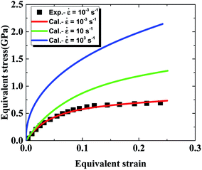
As presented in Table 1, parameters β*, α*, k0 describing the dislocation kinetics are tuned to fit the stress–strain curve of LLM-105 single crystal at a strain rate of 10−3 s−1.21 From Fig. 1, the calculated stress strain curve could well reproduce the experimental results, and the mechanical response shows significant strain rate dependency.
 | (13) |
 | (14) |
 | (15) |
| G1 | G2 | G3 | G4 | G5 | G6 | G7 | G8 | G9 | G10 | G11 | G12 | G13 |
| 0.0042 | 0.0074 | 0.0158 | 0.038 | 0.0676 | 0.0891 | 0.1156 | 0.1422 | 0.1622 | 0.2218 | 0.4753 | 2.6181 | 12.883 |
| G14 | G15 | G16 | G17 | G18 | G19 | G20 | G21 | G22 | E (MPa) | ρ (kg m−3) | ν | |
| 52.481 | 223.87 | 436.52 | 457.09 | 346.74 | 251.19 | 177.83 | 117.49 | 75.858 | 0.77 | 900 | 0.499 |
3. Numerical model
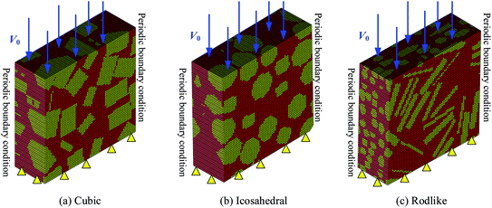
A Representative Volume Element (RVE) generation algorithm was developed to construct three typical crystal morphologies (cubic, icosahedral, rodlike) of LLM-105 based explosives as shown in Fig. 2. In the three-dimensional computational models, the volume fraction of the explosive crystals is approximately 60%.The proposed constitutive model was implemented to the material user subroutines VUMAT in the finite element code Abaqus/Explicit. The 0.3 mm × 0.3 mm × 0.1 mm models were constructed using eight-noded linear brick elements (C3D8) and were partitioned to 126![[thin space (1/6-em)]](https://www.rsc.org/images/entities/char_2009.gif) 750 elements. We investigated the time step and mesh size dependency by using the time step of 10−11 s and 10−13 s and the mesh size of 3 μm and 1 μm, and obtained the same results by pilot calculations. Therefore, the models were resolved with the time step of 10−11 s and the mesh size of 3 μm. The top surface is imposed with a constant impact velocity of 200 m s−1 and 500 m s−1 and the bottom surface is fixed. All the lateral surfaces are constrained with periodic boundary conditions. Initial temperatures are set to be 300 K.
750 elements. We investigated the time step and mesh size dependency by using the time step of 10−11 s and 10−13 s and the mesh size of 3 μm and 1 μm, and obtained the same results by pilot calculations. Therefore, the models were resolved with the time step of 10−11 s and the mesh size of 3 μm. The top surface is imposed with a constant impact velocity of 200 m s−1 and 500 m s−1 and the bottom surface is fixed. All the lateral surfaces are constrained with periodic boundary conditions. Initial temperatures are set to be 300 K.
4. Results and discussions
Fig. 3 compares the volume averaged stress strain curves of cubic, icosahedral and rodlike explosive samples (i.e. cubic, icosahedral and rodlike LLM-105 crystal based explosives) at an impact velocity of 200 m s−1 and 500 m s−1. At an impact velocity of 200 m s−1 (Fig. 3(a)), the strength of cubic explosive reaches as high as 136 MPa, followed by that of the icosahedral explosive at 85 MPa and the strength of rodlike explosive is the lowest at 52 MPa, which greatly lowers the risk of unexpected ignition. Moreover, the hardening modulus of rodlike explosive keeps the lowest during the impact. As the impact velocity increases, the difference of mechanical response among the three samples becomes more pronounced. When the impact velocity increases to 500 m s−1 (Fig. 3(b)), the stress strain curve of the rodlike sample is below that of the cubic and icosahedral samples, indicating that dislocation hardening effect of the rodlike sample is less significant. The strength of the rodlike sample is 69 MPa, lower than that of cubic sample (171 MPa) and icosahedral sample (108 MPa).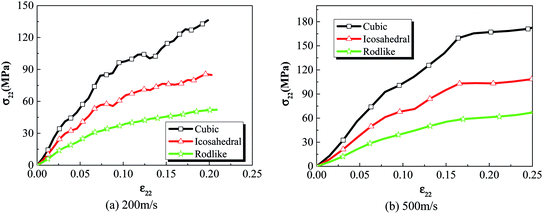 | ||
| Fig. 3 Volume averaged stress strain curves of cubic, icosahedral and rodlike samples at an impact velocity of (a) 200 m s−1 and (b) 500 m s−1. | ||
Volume averaged stress strain curves reflect the macroscale mechanical behavior under impact loading. To analyze the localized stress distribution, Fig. 4 and 5 present the Von Mises stress contours at t = 3 μs of cubic, icosahedral and rodlike samples at an impact velocity of 200 m s−1 and 500 m s−1, respectively. From Fig. 4, as stress wave propagates in the samples, the explosive crystals take most of the stress, while the softer polymer binder accommodates more deformation. The stress distributes non-uniformly due to the heterogeneous microstructure. The cubic explosive has the maximum stress at 609 MPa which locates near the impact surface, whereas the stress of rodlike explosive is the lowest at 166 MPa. As the impact velocity increases to 500 m s−1 (Fig. 5), the sample is further compressed. The maximum Von Mises stress of the rodlike sample is 248.1 MPa, which is much lower than cubic crystal (797.8 MPa) and icosahedral crystal (476.5 MPa). These highly stress concentrated areas are prone to the formation of “hot spots”.
 | ||
| Fig. 4 Von Mises stress contour at t = 3 μs of cubic, icosahedral and rodlike samples at an impact velocity of 200 m s−1. | ||
 | ||
| Fig. 5 Von Mises stress contour at t = 3 μs of cubic, icosahedral and rodlike samples at an impact velocity of 500 m s−1. | ||
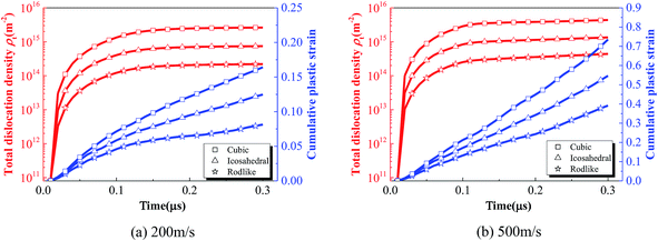
The relatively low stress level and hardening modulus of rodlike explosive at different impact velocities are related to the underlying deformation process. To further explore the deformation mechanism at the mesoscale, Fig. 6 shows the volume averaged total dislocation density and cumulative plastic strain histories of cubic, icosahedral and rodlike samples at an impact velocity of 200 m s−1 and 500 m s−1. At an impact velocity of 200 m s−1, as the wave propagates in the sample, the total dislocation density of all of the three explosives increases rapidly. The dislocation density of the cubic explosive reaches the highest at 2.6 × 10¹⁵ m−2, corresponding to the largest hardening modulus. The dislocation density of rodlike explosive is the lowest at 2.2 × 10¹⁴ m−2 before the saturation state. As the dislocation at the crystal walls and interiors develops, the cumulative plastic strain on each slip system increases gradually as well. The higher dislocation density corresponds to the higher accumulated plastic strain. From the figure, the volume averaged cumulative plastic strain of the cubic explosive is the largest, which indicates more plasticity work is induced during impact. Similarly, at an impact velocity of 500 m s−1, the cubic sample also corresponds to the largest dislocation density at 4.39 × 10¹⁵ m−2 and cumulative plastic strain at 0.73, while the rodlike sample has the lowest dislocation density at 4.4 × 10¹⁴ m−2 and cumulative plastic strain at 0.39.
Fig. 7 and 8 present the spatial distribution of total dislocation density at t = 3 μs of cubic, icosahedral and rodlike samples at an impact velocity of 200 m s−1 and 500 m s−1, respectively. From the figure, most of the dislocation locates near the impact surface. When the stress exceeds the dislocation initiation threshold, dislocation slip starts and expands. At an impact velocity of 200 m s−1, the maximum value of total dislocation density of cubic explosive is 20 times larger than that of rodlike explosive, which shows the dislocation-based hardening plays a more significant role in cubic explosive. As the impact velocity increases, more dislocation develops in the sample. The maximum dislocation density of the cubic sample reaches as high as 1.437 × 10¹⁶ m−2, while that of the rodlike sample is about 8.908 × 10¹⁴ m−2. During the loading process, the dislocation motion of cubic and icosahedral samples is more significant, including the generation of new dislocations and expansion of existing dislocations, while the total dislocation density of rodlike sample is much lower, which is the main reason for the smaller hardening effect and lower temperature rise.
 | ||
| Fig. 7 Total dislocation density contour at t = 3 μs of cubic, icosahedral and rodlike samples at an impact velocity of 200 m s−1. | ||
 | ||
| Fig. 8 Total dislocation density contours at t = 3 μs of cubic, icosahedral and rodlike samples at an impact velocity of 500 m s−1. | ||
The crystal size relates to the total dislocation density as indicated in eqn (5). As dislocation accumulates near the crystal wall, the crystal size decreases as shown in Fig. 9. The original crystal size of the explosive crystals is set to be 35 μm according to previous measurement,25 but quickly decreases to ∼0.1 μm in the time period of 0.1μs, which indicates a “sharpening” process of the crystal walls at very large strains. The decrease of crystal size of cubic explosive is much faster than the other two explosives. The quick broken of explosive crystals enhances the possibility of formation of potential hot spots and temperature increases.
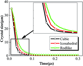 | ||
| Fig. 9 Volume averaged crystal size history of cubic, icosahedral and rodlike samples at an impact velocity of 200 m s−1. | ||
Fig. 10 and 11 show the temperature contours of cubic, icosahedral and rodlike samples at an impact velocity of 200 m s−1 and 500 m s−1. It is interesting to note that the temperature rise varies significantly under the same loading condition. At an impact velocity of 200 m s−1, the maximum temperature is 540 K for the cubic sample, while for the rodlike sample, it is only 313 K. When the impact velocity increases to 500 m s−1, the temperature reaches as high as 682.8 K for the cubic sample and some locations are even ignited, while for the rodlike sample, the temperature rise is only 175.3 K.
 | ||
| Fig. 10 Temperature contours at t = 3 μs of cubic, icosahedral and rodlike samples at an impact velocity of 200 m s−1. | ||
 | ||
| Fig. 11 Temperature contours at t = 3 μs of cubic, icosahedral and rodlike samples at an impact velocity of 500 m s−1. | ||
From the figures, most of the temperature rise locates near the impact face for the three samples.
We further extract the temperature history of maximum temperature rise elements from the three samples at an impact velocity of 200 m s−1 and 500 m s−1 and plot them in Fig. 12. At an impact velocity of 200 m s−1, for the cubic explosive, the temperature rises gradually, followed by a quick increase due to the release of chemical reaction. The chemical reaction degree of the cubic explosive is about 0.3 while that of the other two explosives is on the order of 10−5. The volumetric and dislocation-based plasticity work is high enough to trigger the chemical reaction. On the contrary, the temperature rise of the rodlike explosive is the lowest, which indicates that the volumetric and plasticity work during the loading process is small. Fig. 13 presents the reaction extent at t = 3 μs of cubic, icosahedral and rodlike samples at an impact velocity of 500 m s−1. The reaction extent of the cubic explosive reaches 1.0 at 0.15 μs and temperature rise due to volumetric work, plasticity work and chemical reaction leads to the ignition of the cubic explosive. By contrast, the temperature of rodlike explosive is the lowest. Therefore, it is further implied that the impact sensitivity of the rodlike explosive is the lowest, which is verified by drop hammer tests by Tran et al.18 As the rodlike LLM-105 crystal is obtained by slow recrystallization from warm DMSO (dimethyl sulfoxide) with hot water, the results presented above guide the design of LLM-105 single crystal applied at impact loading.
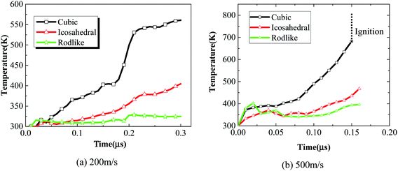 | ||
| Fig. 12 Maximum temperature histories of cubic, icosahedral and rodlike samples at an impact velocity of (a) 200 m s−1 and (b) 500 m s−1. | ||
 | ||
| Fig. 13 Reaction extent at t = 3 μs of cubic, icosahedral and rodlike samples at an impact velocity of 500 m s−1. | ||
Comparatively speaking, the rodlike explosive has the largest aspect ratio and interaction area with binder among the three types explosives. Therefore, the stress concentration is much lower under impact. Moreover, as shown in Fig. 6, at the same impact velocity, the rodlike sample has the lowest total dislocation density, which indicates the plastic work hardening is the least significant. Considering the elastic modulus of the three explosives is the same, thus the lowest stress level of the rodlike sample is understandable. Also, the lowest work hardening effect induces lowest plasticity work. As the temperature increase is contributed by volumetric and plasticity work, the temperature rise of the rodlike sample remains the lowest. The calculated results help to understand the impact sensitivity difference of the three samples.
To investigate the effect of initial dislocation density, different initial dislocation densities (1 × 10¹⁰ m−2, 1 × 10¹¹ m−2, 1 × 10¹² m−2) were selected to analyze the thermomechanical ignition response of rodlike samples at an impact velocity at 500 m s−1. Fig. 14 and 15 display the volume averaged stress strain curves and Von Mises stress contours for rodlike samples with different initial dislocation densities, respectively. It can be seen from the figure that the samples with higher initial dislocation density correspond to higher volume average stress and localized stress than samples with lower initial dislocation density, which is also due to the dislocation hardening effect described above. The strength of the sample with the dislocation density of 1 × 10¹² m−2 is 94 MPa, while for the sample with the dislocation density of 1 × 10¹⁰ m−2, the strength is only 44 MPa. Moreover, for the sample with the dislocation density of 1 × 10¹² m−2, the localized Mises stress is much higher than the other samples.
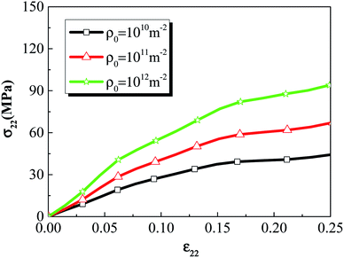 | ||
| Fig. 14 Volume averaged stress strain curves of rodlike samples with initial dislocation density of 1 × 10¹⁰ m−2, 1 × 10¹¹ m−2, and 1 × 10¹² m−2. | ||
 | ||
| Fig. 15 Von Mises stress contours of rodlike samples with initial dislocation density of: (a) 1 × 10¹⁰ m−2, (b) 1 × 10¹¹ m−2, and (c) 1 × 10¹² m−2. | ||
Different initial dislocation densities correspond to different initial particle sizes, and the larger the initial dislocation density, the smaller the initial crystal size. Fig. 16 presents the crystal size history of rodlike samples with initial dislocation density of 1 × 10¹⁰ m−2, 1 × 10¹¹ m−2 and 1 × 10¹² m−2. From the figure, the crystal size of all three samples decreases rapidly to about 0.1 μm in the time of ∼0.1 μs, indicating that under the large deformation, the sharpening effect occurs due to the accumulation of dislocations at the crystal wall, which in turn causes rapid refinement of the explosive crystals. The rapid breakage of the explosive crystals forms cracks, which will lead to the formation of potential hot spots and even ignition. As the initial dislocation density increases (initial crystal size decreases), the corresponding crystal size decreases at a lower rate.
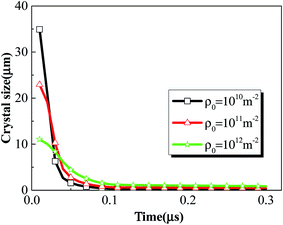 | ||
| Fig. 16 Crystal size history of rodlike samples with initial dislocation density of 1 × 10¹⁰ m−2, 1 × 10¹¹ m−2, and 1 × 10¹² m−2. | ||
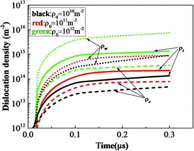
Fig. 17 shows total dislocation density ρt, dislocation density at crystal wall ρw and dislocation density at crystal interior ρc histories of rodlike samples with initial dislocation density of 1 × 10¹⁰ m−2, 1 × 10¹¹ m−2, and 1 × 10¹² m−2. For all the samples, the ratio between the dislocation densities of crystal walls and interiors increases with time and approaches about 10 at 0.2 μs. The total dislocation density, dislocation density at the crystal interior and wall increase relatively slowly at initial dislocation density of 1 × 10¹⁰ m−2, 1 × 10¹¹ m−2. However, when the initial dislocation density increases to 1 × 10¹² m−2, the dislocation density (green dotted curve) at the crystal wall increases sharply, causing the total dislocation density under this initial condition to be much higher than the above two cases, which can explain the more pronounced hardening effect.
Fig. 18 and 19 shows the temperature contours and volume averaged temperature histories of rodlike samples with initial dislocation density of 1 × 10¹⁰ m−2, 1 × 10¹¹ m−2, and 1 × 10¹² m−2. From the figures, the sample with a larger initial dislocation density corresponds to a higher volume averaged and localized temperature rise. Considering the chemical reaction is not triggered for all cases, the higher dislocation based plasticity work from the sample with a larger initial dislocation contributes to the higher temperature rise. From Fig. 18, some reverberations are shown in the temperature histories, which is due to the propagation and reflections of elastic waves. Therefore, samples with more initial defects (i.e. dislocation) undergo more plastic deformation and the plasticity work will further contribute to the temperature rise, which lead to a higher impact sensitivity.
 | ||
| Fig. 18 Temperature contours of rodlike samples with initial dislocation density of: (a) 1 × 10¹⁰ m−2, (b) 1 × 10¹¹ m−2, and (c) 1 × 10¹² m−2. | ||
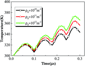 | ||
| Fig. 19 Volume averaged temperature histories of rodlike samples with initial dislocation density of 1 × 10¹⁰ m−2, 1 × 10¹¹ m−2, and 1 × 10¹² m−2. | ||
Actually, dislocation based model has been widely developed and used to quantify the thermomechanical ignition response of typical high explosive crystal – HMX and RDX single crystal.26–28 In their model, dislocation based plasticity is assumed to be the primary plastic deformation mechanism. Previous works from Armstrong19 proposed a dislocation based cleavage model for explosive crystal that dislocations accumulate near the obstacles such as crystal wall, and when the resolved shear stress reaches a critical value, dislocation pile-ups break through the obstacles, and large crystal breaks into smaller pieces. Similarly, we used the dislocation based model for LLM-105 single crystal in this work. The assumption of dislocation based deformation mechanism is supported by the evidence of plastic deformation and cleavage cracks of the residual impressions for nanoindentation tests on LLM-105 single crystal.21 Therefore, the including of physical process from dislocation-based plasticity to “dislocation avalanche” induced cleavage fracture for LLM-105 single crystal is reasonable.
Also, the decrease of crystal size in Fig. 9 and 16 is actually that the LLM-105 single crystal fractures into a large number of smaller crystals, which is an implication based on the constitutive properties of the material. A dislocation Mean Free Path (MFP) was applied to represent the distance travelled for a dislocation segment before it is stopped by an obstacle such as crystal wall.29,30 In the present work the dislocation MFP is assumed to be the crystal size, which is related to the total dislocation density. Although the model parameters were calibrated through stress–strain curve and the calculated results were in qualitative agreement with the drop hammer tests,18 a more accurate set of dislocation related parameters determined by experiments or molecular dynamics simulations are needed.
5. Conclusion
A elastoviscoplastic dislocation model is developed for LLM-105 crystal, which accounts for the dislocation evolutions at crystal interiors and crystal walls, and strain-rate dependent work hardening. Three typical crystal morphologies (cubic, icosahedral, rodlike) of LLM-105 based explosives computational models were constructed and subjected to an impact velocity of 200 m s−1 and 500 m s−1. Effect of crystal morphology and initial dislocation density on the mesoscale thermomechanical ignition behavior of LLM-105 based explosives have been investigated.Mises stress, dislocation density as well as temperature distribute non-uniformly due to the heterogeneous microstructure. Both the volume averaged stress level and dislocation density are the lowest for the rodlike explosive. Therefore, the volume averaged temperature contributed from volumetric and plasticity work is the lowest. The differences in dislocation densities between the walls and crystal interiors increase with time, which indicates higher possibility of larger crystals breaking into smaller crystals, until reaching the ultrafine crystal size. At the mesoscale, the maximum stress, dislocation and temperature locate near the impact surface for all three types of explosives. For the cubic explosive, chemical reaction is triggered, which leads to a significant increase in the temperature profile. At the impact velocity of 500 m s−1, temperature rise due to volumetric work, plasticity work and chemical reaction is sufficiently high to lead to the ignition of the cubic explosive. On the contrary, the temperature of the rodlike and icosahedral explosive rises moderately. Thus, the simulation results show that the rodlike explosive is the least sensitive among the three explosives, which is in qualitative agreement with the drop hammer tests. Moreover, with the increase of initial dislocation density, the corresponding volume averaged and localized stress and temperature increase as well.
Results presented above bridge the macroscale thermomechanical ignition response with the mesoscale deformation mechanisms, which could be directly compared with experimental results as well as reveal the related underlying deformation mechanisms. More realistic formulations models (higher LLM-105 contents) should be constructed to analyze and compare the thermomechanical ignition response with real explosive to better understand the ignition mechanisms and guide the design of LLM-105 based formulations. In the future, more mesoscale thermomechanical parameters from experiments or molecular dynamic simulations of LLM-105 single crystal are needed to determine the related parameters more accurately. Also, other inelastic deformation mechanisms such as twinning and phase transition should be incorporated in the present model.
Conflicts of interest
There are no conflicts to declare.Acknowledgements
The authors would like to thank the National Natural Science Foundation of China (No. 11802024 & No. 11872119), the Science Challenging Program (TZ2016001), Pre-research Project of Armament (No. 1421002020101-01), China Postdoctoral Science Foundation (2018M631363) and Development of Mesoscale Model for the Size Effect of Shock Initiation Contract of China Academy of Engineering Physics for supporting this project.References
- T. Tran, P. Pagoria, D. Hoffman, J. Cutting, R. Lee and R. Simpson, Characterization of 2, 6-diamino-3, 5-dinitropyrazine-1-oxide (LLM-105) as an insensitive high explosive material, Lawrence Livermore National Lab., CA, US, 2002 Search PubMed.
- P. F. Pagoria, Synthesis, scale-up, and characterization of 2, 6-diamino-3, 5-dinitropyrazine-1-oxide (LLM-105), Lawrence Livermore National Lab., CA, United States, 1998 Search PubMed.
- X. Zhao and Z. Liu, J. Chem. Res., 2013, 37, 425–426 CrossRef CAS.
- P. F. Pagoria, G. S. Lee, A. R. Mitchell and R. D. Schmidt, Thermochim. Acta, 2002, 384, 187–204 CrossRef CAS.
- A. J. Bellamy and P. Golding, New Trends Res. Energ. Mater., Proc. Semin., 11th, 2008, 465–474 Search PubMed.
- M. R. Manaa, I.-F. W. Kuo and L. E. Fried, J. Chem. Phys., 2014, 141, 064702 CrossRef.
- J. C. Gump, C. A. Stoltz, B. P. Mason, B. G. Freedman, J. R. Ball and S. M. Peiris, J. Appl. Phys., 2011, 110, 073523 CrossRef.
- R. K. Weese, A. K. Burnham, H. C. Turner and T. D. Tran, J. Therm. Anal. Calorim., 2007, 89, 465–473 CrossRef CAS.
- W.-D. He, G. Zhou, N.-B. Wong, A.-M. Tian and X.-P. Long, J. Mol. Struct.: THEOCHEM, 2005, 723, 217–222 CrossRef CAS.
- Z. Xu, H. Su, X. Zhou, X. Wang, J. Wang, C. Gao, X. Sun, R. Dai, Z. Wang and H. Li, J. Phys. Chem. C, 2018, 123, 1110–1119 CrossRef.
- P. Hsu, M. Zhang, P. Pagoria, H. Springer and L. Fried, AIP Conf. Proc., 2017, 1793, 040033 CrossRef.
- P. Hsu, S. Strout, G. Klunder, E. Kahl, N. Muetterties, J. Reynolds and M. Gresshoff, AIP Conf. Proc., 2018, 1979, 160010 CrossRef.
- C. M. Tarver, P. A. Urtiew and T. D. Tran, J. Energ. Mater., 2005, 23, 183–203 CrossRef CAS.
- W. Xu, C. An, J. Wang, J. Dong and X. Geng, Propellants, Explos., Pyrotech., 2013, 38, 136–141 CrossRef CAS.
- B. Tan, X. Long, R. Peng, H. Li, B. Jin and S. Chu, J. Phys. Chem. A, 2011, 115, 10610–10616 CrossRef CAS PubMed.
- F. Garcia, K. S. Vandersall, C. M. Tarver and P. A. Urtiew, J. Phys.: Conf. Ser., 2007, 500, 052048 CrossRef.
- P. Vitello, T. Lorenz, L. Fried and P. Souers, High Resolution Chemistry Based Modeling of LLM-105 Explosives, Lawrence Livermore National Laboratory (LLNL), Livermore, CA, 2014 Search PubMed.
- T. Tran, P. Pagoria, D. Hoffman, B. Cunningham, R. Simpson, R. Lee and J. Cutting, Small-scale safety and performance characterization of new plastic bonded explosives containing LLM-105, Proc. 12th Int. Det. Symp., 2002, pp. 440–447 Search PubMed.
- R. Armstrong and W. Elban, Mater. Sci. Technol., 2006, 22, 381–395 CrossRef CAS.
- R. D. Gilardi and R. J. Butcher, Acta Crystallogr., Sect. E: Struct. Rep. Online, 2001, 57, o757–o759 CrossRef CAS.
- S. O. Kucheyev, A. E. Gash and T. Lorenz, Mater. Res. Express, 2014, 1, 025036 CrossRef.
- Y. Estrin, L. Toth, A. Molinari and Y. Bréchet, Acta Mater., 1998, 46, 5509–5522 CrossRef CAS.
- L. s. S. Tóth, A. Molinari and Y. Estrin, J. Eng. Mater. Technol., 2002, 124, 71–77 CrossRef.
- E. Mas, B. Clements, W. Blumenthal, C. Cady, G. Gray and C. Liu, AIP Conf. Proc., 2002, 1, 661–664 CrossRef.
- D. Hoffman, K. Lorenz, B. Cunningham and F. Gagliardi, Formulation and mechanical properties of LLM-105 PBXs, Lawrence Livermore National Lab. (LLNL), Livermore, CA, United States, 2008 Search PubMed.
- X. Wang, Y. Wu and F. Huang, J. Hazard. Mater., 2017, 321, 256–267 CrossRef CAS PubMed.
- X. Wang, Y. Wu, F. Huang, T. Jiao and R. J. Clifton, Mech. Mater., 2016, 99, 68–78 CrossRef.
- D. J. Luscher, F. L. Addessio, M. J. Cawkwell and K. J. Ramos, J. Mech. Phys. Solids, 2017, 98, 63–86 CrossRef CAS.
- P. Ambrosi and C. Schwink, Supply Chain Manag., 1978, 12, 303–308 CAS.
- L. Kubin, B. Devincre and T. Hoc, Acta Mater., 2008, 56, 6040–6049 CrossRef CAS.
| This journal is © The Royal Society of Chemistry 2019 |


