 Open Access Article
Preparation of core–shell structured metal–organic framework@PANI nanocomposite and its electrorheological properties
Qingkun Wena,
Lili Maab,
Chengwei Wanga,
Baoxiang Wang *ab,
Rongjiang Hana,
Chuncheng Hao*ab and
Kezheng Chena
aCollege of Materials Science and Engineering, Qingdao University of Science and Technology, Qingdao 266042, PR China. E-mail: bxwang@qust.edu.cn; hao@qust.edu.cn; Fax: +86-532-84022509; Tel: +86-532-84022509
bState Key Laboratory of Power Transmission Equipment & System Security and New Technology, Chongqing University, Chongqing 400044, PR China
First published on 9th May 2019
Abstract
A novel core–shell-type electrorheological (ER) composite material was fabricated via using polyaniline as an insulating layer to the outer surface of the core conductive metal–organic framework (MIL-125) with controlled size and morphology. MIL-125 was firstly synthesized by a solvothermal method, and then polyaniline was synthesized in a polar solvent and a tight coating was successfully achieved to form a MIL-125@PANI core–shell nanocomposite. This core–shell structure greatly enhances the polarization ability of dispersed particles, thereby improving their rheological properties. The morphology of pure MIL-125 and MIL-125@PANI has been characterized by transmission electron microscopy (TEM) and scanning electron microscopy (SEM). Their structure was characterized by X-ray powder diffraction. Moreover, the ER activity of MIL-125-based and MIL-125@PANI-based ER fluids by dispersing the particles into silicone oil was studied using a rotational rheometer. The results show that the MIL-125@PANI composite particles have higher ER properties.
1. Introduction
Intelligent fluids are currently receiving widespread attention and they can respond to various environmental stimuli such as temperature, pH, stress, external magnetic or electric field.1–3 As a typical smart material, electrorheological (ER) fluid is a general term for a class of liquids, which is prepared by dispersing polarizable particles into an insulating medium fluid such as mineral or silicone oil.4,5 The shear stress of the so-called ER liquid increases significantly with the increase of the electric field strength. When the external electric field increases to a certain value, the rheological properties of the ER fluid will be changed.6–8 This changed process is very fast, usually within a few milliseconds, and the conversion process is reversible. This means that the rheological properties of the ER fluids vary with the external applied electric field. When the electric field is applied, the solid particles in the ER fluid will form a chain or columnar structure along the direction of the electric field, causing the ER fluid to change from liquid to solid-like. In this case, its rheological properties will be greatly improved, including shear stress, yield stress and storage/loss modulus,9–12 etc. ER fluids have great application prospects in many fields, including brake/clutch, engine mounts, dampers, and medical haptic devices.13–15At present, the research on ER fluids mainly focuses on dispersed phase particles, which generally have a high dielectric constant and/or appropriate conductivity. The dispersed phase particles can be made of inorganic materials, organic polymer materials, and composite materials, etc.16–19 Among them, composite materials generally consist of a core conductive layer and an insulating layer. The core conductive layer can make the particles rapidly polarize under the action of an electric field and can control the density and shape of the particles. The outermost insulating layer is mainly used to reduce the conductivity, protect the polarization charge does not spread, and control the electrostatic interaction between the particles.20–22 In this way, the rheological properties can be improved.
Metal–organic framework (MOF) materials are periodic porous materials formed by self-assembly of transition metal ions and organic ligands. They are affected in many fields due to their high porosity, low density, and large specific surface area.23,24 The size and shape of the MOF particles has an important effect on its function. From previous report, the amount of surfactant CTAB can control the morphology of the coordination polymer [Cu3(BTC)2], and even reduce the particle size to the nanoscale.24 However, MOF is not suitable for the direct using as the dispersed phase of ER material. Because MOF has a large conductivity and it is easy to short-circuit or breakdown due to excessive leakage current density under the application of an external electric field.25–27 In these cases, it may be used as the core conductive layer and compound with an insulating polyaniline on its surface to form an excellent dispersion of ER fluid. We can achieve step-less regulation by preparing such an ER fluid as a shock absorber, and can effectively prevent resonance. At the same time, when driving on different roads, this kind of electro-variable shock absorber can intelligently and effectively change the shock absorption to adapt to different situations, and this effect is better than the effect of the spring shock absorber.
In this work, we prepared a coordination polymer Ti8O8(OH)4(BDC)6 (MIL-125, a form of the as-called Ti-incorporated MOF) by solvothermal method.28 MIL-125 is a photosensitive material with three-dimensional pore structure self-assembled from an octameric ring of Ti–O octahedron and phthalic acid.29 Polyaniline (PANI) is one of the most well-known conductive polymers and it has been widely investigated because of its great advantages, for example, ease of synthesis, low cost, good chemical stability, sensitive response to an electric field, and reversible doping–dedoping process to control the conductivity.30–32 Then, an outer-layer of polyaniline is compounded on the surface of MIL-125 in a polar solvent (Dimethylformamide, DMF) to form a new composite material: MIL-125@PANI nanocomposite. It has various advantages of the MOF structure and its stability is improved. The conductivity of MIL-125@PANI is greatly reduced due to its combination of a layer of polyaniline. The composite material of this structure has strong polarization ability and its rheological property is improved greatly. The core/shell MIL-125@PANI particles were dispersed in silicone oil to prepare the ER fluid and their rheological properties were measured at electric field strengths ranging from 0 kV mm−1 to 3 kV mm−1. We can see that its ER performance has been significantly improved.
2. Experimental section
2.1 Materials
Dimethylformamide (DMF, Laiyang Fine Chemical Factory, China), anhydrous methanol (CH4O, Tianjin Fuyu Fine Chemical Co. Ltd., Tianjin, China), acetic acid (CH3COOH, Tianjin Ruijinte Co., Ltd., Tianjin, China), titanium tetrabutoxide (TBT, Beijing Chemicals, Beijing, China), cetyltrimethyl ammonium bromide (CTAB, Tianjin Bodi Chemical Co. Ltd., China), 1,4-benzenedicarboxylic acid (BDC, Sinopharm Chemical Reagent Corporation, Shanghai, China), aniline monomer (Laiyang Fine Chemical Factory, China), ammonium persulfate (APS, ≥98.0% purity, Beijing Chemicals, China) and silicone oil (polydimethylsiloxane, viscosity: 500 cSt, dielectric constant: 2.63–2.73, density ρ: 0.973 g cm−3, Tian Jin Damao limited company, Tianjin, China) were purchased. All materials were used without any treatment.2.2 The synthesis of MIL-125
MIL-125 is synthesized by a solvothermal method. Firstly, 5 g BDC and 1 g CTAB were added to a mixture of 100 mL DMF and 15 mL anhydrous methanol, and fully stirred until the mixture was completely dissolved. Subsequently, 5 mL acetic acid was added to the above-solution, which is aimed to prevent the hydrolysis of titanium precursor. After stirring for 10 minutes, 3 mL TBT was added to the above-solution and keep stirring for 30 minutes. Finally, the as-obtained solution was transferred into the autoclave and then reacted under 150 °C for 24 hours. After cooling down, the resulting white product was washed with DMF and anhydrous methanol for several times. The final product was dried in an oven at 65 °C for 12 h.2.3 The synthesis of MIL-125@PANI nanocomposite
The obtained white MIL-125 solid was dispersed into 100 mL DMF solution, and then 2 mL aniline monomer was added into above solution and stirred continually for 3 h under ice bath. After that, 2 g APS was dissolved in a mixture solution of 50 mL DMF and 0.5 mL water. Then, the APS solution was slowly added to the aniline mixture solution and stirred for 30 minutes under ice bath. The resultant solution was centrifuged and washed with ethanol and water to remove the un-reacted aniline monomer. Finally, the MIL-125@PANI particles were dried at 70 °C in a vacuum oven for 12 h.2.4 The synthesis of ER fluids
The 10 wt% ER fluids were fabricated by dispersing the as-obtained MIL-125@PANI in silicone oil.2.5 Characterization
The morphology of the fabricated MIL-125@PANI nanocomposite particles were observed by using a field emission scanning electron microscopy (FESEM, JEOL JSM-6700 F) with an accelerating voltage of 20 kV. TEM images were investigated on a JEOL-2100 high-resolution transmission electron microscopes (Hitachi, Ltd., Tokyo, Japan) operating at 200 kV. For the TEM investigation, small amounts of as-obtained sample dispersed in ethanol was performed an ultrasonic treatment for about 5 min and then be dropped onto a copper grid covered by a carbon film. Its structure was analyzed via a powder X-ray diffraction (XRD, Rigaku D/MAX-2500/PC) equipped with a rotating anode and a Cu Kα radiation source (λ = 1.5406 Å), within the range of 2 theta from 4 to 80°. All studies were taken by using the same condition as follow: a scanning rate 5° min−1, a generator voltage of 40 kV and a current of 100 mA.The rheological properties of pure MIL-125-based and MIL-125@PANI-based ER fluids were, respectively, studied by a rotational rheometer (HAAKE Rheo Stress 6000, Thermo Scientific, Germany) with a parallel plate system (PPER35, the gap between plates was 1.0 mm), and WYZ-020 DC high-voltage generator (voltage: 0–5 kV, current: 0–1 mA), and a temperature controller. The steady flow curves of shear stress–shear rate were measured by the controlled shear rate (CSR) mode within 0.1–500 s−1 at room temperature. Before every measurement, the ER suspensions will be pre-sheared for 60 s at 300 s−1 and then electric fields were applied. The so-called yield stress can be approximately obtained with the maximum shear stress values at the low shear rate region. In addition, the dielectric properties of the MIL-125-based and MIL-125@PANI-based ER fluid were detected by using a Novolcontrol broad-band dielectric spectroscopy equipment (Novolcontrol Concept 40, Germany). All experiments were carefully performed at 25 °C.
3. Results and discussion
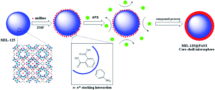
We have studied a series of synthetic methods for MIL-125@PANI core–shell microspheres, as described in Scheme 1. It is synthesized mainly through a two-step process: (1) the core MOF material was synthesized by solvothermal method; (2) control monomer bonding at the interface is occured and then a coating PANI layer was formed via an in situ chemical oxidation polymerization. When aniline monomer is added to MIL-125 solution, π-electrons of aromatic systems in the MIL-125 and aniline monomer certainly were combined through π–π* stacking, resulting in a non-covalent functionalization of core particles.33 In addition, the structure of MOF tends to be round, which provides a core for the growth of polyaniline and facilitates the tight connection between materials.The external morphology of MIL-125 and MIL-125@PANI particles was observed by SEM technique. As shown in Fig. 1(a) and (b), the shape of as-obtained MIL-125 particle is approximately a spherical morphology with an average size of about 200–300 nm. And it has a smooth surface and mono-dispersed size. In particular, CTAB has recently been used to synthesize MOF particles and it can adjust the morphology and size of the particles.33,34 It can be seen from Fig. 1(c) and (d) that the morphology of the MIL-125@PANI nanocomposite particles is basically the same as that of the pure MIL-125, but the average size of the MIL-125@PANI nanocomposite particles also increases slightly, which indicates that polyaniline was successfully coated on the outer surface of the MOF structure in a polar solvent.
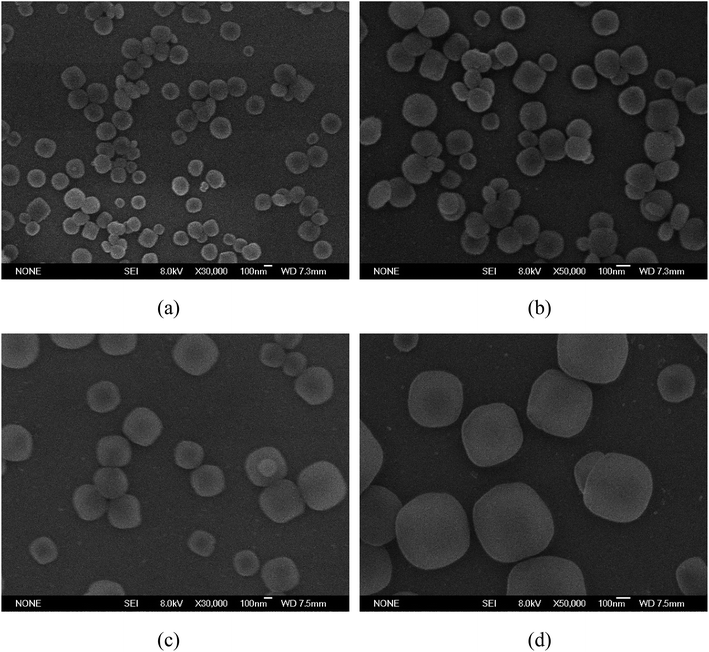 | ||
| Fig. 1 SEM images of as-synthesized MIL-125 particles (a and b) and MIL-125@PANI particles (c and d). | ||
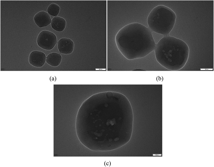
Core/shell structured MIL-125@PANI particles can be clearly confirmed by TEM images in Fig. 2. From these TEM images, we can see that the core–shell structure is very clear, the synthesized PANI layer surrounding the MIL-125 core. The sizes of MIL-125@PANI particles depicted in the TEM micrographs are monodispersed, which is consistent with the results observed in the SEM images. The thickness of outer polyaniline layer is about 70–90 nm, which greatly improves the stability and rheological properties of the MOF structure.
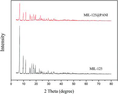
The XRD patterns of pure MIL-125 and MIL-125@PANI are shown in Fig. 3, respectively. As displayed in Fig. 3, the XRD pattern of pure MIL-125 corresponds well with the previous report about MIL-125. By comparing the characteristic peaks of XRD, we can see that the characteristic peak of MIL-125@PANI is basically the same as that of MIL-125. We believe that the crystal structure of the composites does not change, and the metal–organic framework structure remains good. The metal–organic framework greatly enhances its polarization ability due to its unique structure, which greatly enhances its rheological properties. However, the intensity of the characteristic peaks is reduced after the formation of MIL-125@PANI particles, which can prove that PANI is successfully coated on the MIL-125 to some extent.
The conductivity has a crucial influence on its rheological properties. Normally, the suitable range of electrical conductivity of the ER material is 10−8 to 10−10 S cm−1, and adjusting the conductivity to this range is beneficial to enhance its ER activity.35 In addition, in previous reports, Block et al. proposed that the ER fluid exhibiting the best ER effect has an electrical conductivity of about 10−9 S cm−1, because the strength of interfacial polarization, in this case, can reach a maximum value.35 We can calculate the conductivity of the ER suspensions by the formula σ = j/E, where j is the current density through ER suspension, E is the applied electric field strength. Thus, the conductivity of the MIL-125@PANI particles could be studied by the following conductivity equation:36–38
| σ = (1 − φ)σf + φσp | (1) |
The conductivity of pure MIL-125 and MIL-125@PANI ER suspensions are shown in Table 1. The conductivity of MIL-125@PANI maintained within the range of 10−10 to 10−8 S cm−1 and it is good for enhancing ER effect. But the pure MIL-125-based ER fluid possess a high conductivity and shown a break down behavior under E = 2.5 kV mm−1. These results verify that the outer polyaniline reduces its conductivity and enhances ER behavior.
| I/μA | j/μA cm−2 | E/kV mm−1 | σ/S cm−1 | σp/S cm−1 | |
|---|---|---|---|---|---|
| MIL-125 | 950 | 192.85 | 2 | ∼9.64 × 10⁻⁹ | 1.06 × 10⁻⁷ |
| MIL-125@PANI | 40 | 8.12 | 3 | ∼2.64 × 10⁻¹⁰ | ∼2.9 × 10⁻⁹ |
The ER characteristics of the MIL-125 and MIL-125@PANI ER suspensions were analyzed in a controlled shear rate (CSR) mode, and it can show the effect of an applied electric field on the flow behavior of ER fluid. The shear rate ranges from 0.1 s−1 to 500 s−1 and the electric field gradually increases from 0 kV mm−1 to 3.0 kV mm−1. The curves of shear stress as a function of the shear rate under different applied electric field are shown in the Fig. 4(a) and (b). When no applied external electric field is occured, the flow characteristics of the ER fluids are the same as those of Newtonian fluid-like behavior, which shear stress increases linearly with increasing shear rate and the slope approaches 1.39 However, when an electric field is applied, the ER fluids begin to transform toward a “elastic solid”, and the shear stress increases as the electric field strength increases, which presents the performance of Bingham fluid-like behavior.40–44 Because of the formation of the chain-like structure between the dispersed MIL-125@PANI particles, ER fluids exhibited a strong flow resistance. As we can see in Fig. 4(a), as-prepared MIL-125@PANI particles have shown good ER behaviors, a longer plateau region was detected and the shear stress of it can reach more than 200 Pa. We can see that the applied electric field of the pure MIL-125 ER fluid can only reach 2 kV, and continue to increase the voltage will be occurred breakdown (Fig. 4(b)).
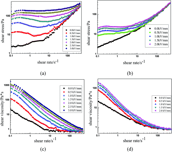 | ||
| Fig. 4 Shear stress and shear viscosity as functions of shear rate for MIL-125@PANI (a and c) and pure MIL-125 (b and d). | ||
As we all know, the properties of ER fluids are mainly due to the chain-like structure or column-like structure formed between the dispersed particles along the direction of electric field. Under the condition of shear flow, the chain-like structure undergoes a process of continuous destruction and recombination. As shown in Fig. 4(a), when the shear rate was low, the shear stress shows a wider plateau region under the application of the electric field. In this process, the chain structure exhibits a dynamic equilibrium between recombination and destruction under the action of electric field strength and shear forces. This is the common feature of the ER fluids. As the electric field strength increases, the electrostatic interaction between the dispersed phase particles increases, resulting in the improvement of the yield stress of the MIL-125@PANI-based ER suspension, which resist the hydrodynamic force. However, when the shear rate is increased to a certain extent, the as-called hydrodynamic force becomes dominant because the destruction rate is faster than the recombination rate, which may result a called pseudo-Newtonian fluid behavior.
In addition, Fig. 4(c) and (d) shows the relationship between the shear viscosity and the shear rate of the pure MIL-125 and MIL-125@PANI ER fluid. It was found that the shear viscosity of the pure MIL-125 and MIL-125@PANI ER fluids decrease with the increase of the shear rate, whether the electric field is applied or not, which is called a phenomenon of shear thinning behavior. Moreover, at low shear rate, the shear viscosity of pure MIL-125 and MIL-125@PANI ER fluids increase with the increase of electric field strength. Therefore, the viscosity of MIL-125@PANI-based ER fluid is varied obviously than that of pure MIL-125 ER fluid, and the shear viscosity increases greatly after the electric field is applied, which indicates that ER fluid has a great application prospect in practice.
Furthermore, we usually use ER efficiency to express the performance of ER fluids,45 as described as follows:
| e = (τE − τ0)/τ0 | (2) |
The Bingham fluid model is usually used to detect the flow curve of ER fluids, which is generally presented as follows:
 | (3) |
![[small gamma, Greek, dot above]](https://www.rsc.org/images/entities/i_char_e0a2.gif) depict the shear rate, and η is used to describe the shear viscosity. The dynamic yield stress can be calculated by deducing the shear rate to a zero limit. However, the unusual decreasing trend of shear stress–shear rate curves is often occurred, appearing in the Fig. 4(a). Therefore, a called Cho–Choi–Jhon (CCJ) model with six parameters46 accurately described the best fit of shear stress behavior of the MIL-125@PANI-based ER fluid over the entire range of shear rate under electric field. The equation is shown as below:
depict the shear rate, and η is used to describe the shear viscosity. The dynamic yield stress can be calculated by deducing the shear rate to a zero limit. However, the unusual decreasing trend of shear stress–shear rate curves is often occurred, appearing in the Fig. 4(a). Therefore, a called Cho–Choi–Jhon (CCJ) model with six parameters46 accurately described the best fit of shear stress behavior of the MIL-125@PANI-based ER fluid over the entire range of shear rate under electric field. The equation is shown as below:
 | (4) |
| MIL-125@PANI | Electric field/kV mm−1 | |||||
|---|---|---|---|---|---|---|
| Parameters | 0.5 | 1 | 1.5 | 2 | 2.5 | 3 |
| τ0 | 8.025 ± 0.132 | 37.504 ± 0.154 | 70.889 ± 0.338 | 51.830 ± 0.71 | 63.705 ± 0.518 | 75.188 ± 1.228 |
| t1 | 0.072 ± 0.02 | 0.117 ± 0.023 | 0.233 ± 0.052 | 0.485 ± 0.082 | 0.544 ± 0.097 | 0.783 ± 0.006 |
| α | 2 ± 0.063 | 1.440 ± 0.033 | 2.006 ± 0.014 | 2.312 ± 0.078 | 2.630 ± 0.022 | 2.77 ± 0.053 |
| β | 0.069 ± 0.006 | 0.069 ± 0.009 | 0.065 ± 0.015 | 0.057 ± 0.017 | 0.053 ± 0.012 | 0.054 ± 0.017 |
| η∞ | 0.198 ± 0.001 | 0.044 ± 0.0007 | 0.016 ± 0.0004 | 0.006 ± 0.0002 | 0.003 ± 0.0001 | 0.002 ± 0.015 |
| t2 | 1.312 ± 0.021 | 1.104 ± 0.009 | 1.118 ± 0.019 | 0.979 ± 0.011 | 0.958 ± 0.005 | 0.96 ± 0.013 |
| Pure MIL-125 | Electric field/kV mm−1 | |||
|---|---|---|---|---|
| Parameters | 0.5 | 1 | 1.5 | 2 |
| τ0 | 6.518 ± 0.137 | 13.205 ± 0.96 | 14.848 ± 0.126 | 22.387 ± 0.517 |
| t1 | 0.015 ± 0.011 | 0.002 ± 0.009 | 0.173 ± 0.005 | 0.007 ± 0.022 |
| α | 1.895 ± 0.154 | 1.805 ± 0.097 | 4.154 ± 0.088 | 2.886 ± 0.01 |
| β | 0.740 ± 0.035 | 0.742 ± 0.422 | 0.732 ± 0.052 | 0.252 ± 0.007 |
| η∞ | 0.061 ± 0.01 | 0.412 ± 0.0003 | 0.0286 ± 0.011 | 0.116 ± 0.006 |
| t2 | 0.945 ± 0.036 | 0.613 ± 0.05 | 0.889 ± 0.059 | 0.112 ± 0.041 |
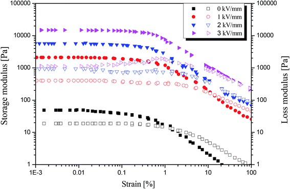
Furthermore, a dynamic oscillation test was carried out to study the visco-elastic behavior of the MIL-125@PANI-based ER fluid, as shown in Fig. 5. The linear viscoelastic region of ER fluid was determined by strain amplitude sweep test with a fixed angular frequency of 6.28 rad s−1 within an adequate strain range from 10−3 to 102%. With or without the application of an electric field, both storage modulus (G′) and loss modulus (G′′) show a plateau region as the strain amplitude increases, and G′ and G′′ begin to decrease until the strain amplitude reaches 1%. And when an electric field is applied, G′ and G′′ are increased to higher values, respectively. In this platform area, G′ is much larger than G′′, which is the so-called linear viscoelastic area (γLVE), in which the deformation of structure is reversible. When the strain amplitude exceeds γLVE, both G′ and G′′ decrease rapidly, and G′′ exceeds G′, because the irreversible change of the chain structure occurs in the ER fluid, and the chain structure begins to break, resulting in a decrease in the elastic properties of ER fluid.
Moreover, the dynamic yield stress of the MIL-125@PANI-based ER fluid is shown in Fig. 6, the drawing is shown by using log–log coordinates. It can be seen that there is a power-law exponential relationship between the yield stress and the electric field intensity according to the results obtained from the model of controlling the shear rate (CSR model). In general, this relationship can be expressed by the following equation:
| τy ∝ Eα | (5) |
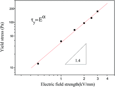 | ||
| Fig. 6 The yield stress as a function of applied electric field strength for MIL-125@PANI-based ER fluid. | ||
The on–off effect of MIL-125@PANI-based ER fluid is shown in Fig. 7. At a constant shear rate, the sensitivity and reversibility of the MIL-125@PANI-based ER fluid can be observed by periodically turning on and off the applied electric field. Whenever a stable electric field is applied, the shear stress of the MIL-125@PANI-based ER fluid rapidly increases to a certain value, when the applied electric field is removed, the ER fluid will quickly drop to zero electric field value. And the whole process of change is very rapid. This indicates that the response of the MIL-125@PANI-based ER fluid to the electric field strength is very sensitive and reversible.
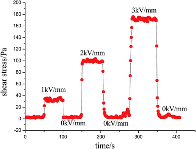 | ||
| Fig. 7 Shear stress of the MIL-125-based ER fluid influenced by alternating on–off state of electric field at a fixed shear rate of 1 s−1. | ||
In general, the intensity of ER performance is also related to the dielectric properties of the material, which can affect the rheological properties by enhancing the polarization between the particles.50 As reported previously, a proper dielectric loss (ε′′) and a large dielectric constant (ε′) can improve the activity of ER fluid.51,52 The relation between the two components of the dielectric constant and the frequency and the Cole–Cole's plot are shown in Fig. 8. The Cole–Cole's equation is usually used to analyze the dielectric spectrum, as described below:
 | (6) |
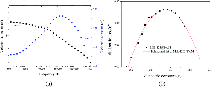 | ||
| Fig. 8 (a) Dielectric constant and loss factor as a function of the frequency and (b) Cole–Cole plot of MIL-125@PANI ER fluid. | ||
4. Conclusion
In summary, we successfully synthesized the core–shell-structured MIL-125@PANI nanocomposite in a polar solvent. SEM and TEM images showed that MIL-125@PANI nanocomposite have a well-defined size distribution with uniform coating layer. Moreover, based on various characterizations, we determined that the as-synthesized MIL-125@PANI could be applied as an ER material and the rheological test showed that the suspension consisting of MIL-125@PANI particles exhibits a strong ER effect. The CCJ model was used to predict the unusual shear stress behavior changed with the applied electric field. A dielectric analysis was performed by measuring the frequency dependence of the dielectric properties for the MIL-125@PANI-based ER fluid, which can better explain the relationship between the particle polarizability and ER effect. The dynamic yield stress showed a power law dependence of the electric field, τy ∝ E1.4, which is consistent with a conduction model. This result of our study provides a useful method for future intelligence materials preparation.Conflicts of interest
There are no conflicts to declare.Acknowledgements
This work was supported by the Shandong Provincial Natural Science Foundation, China (ZR2019MEM051); and Visiting Scholarship of State Key Laboratory of Power Transmission Equipment & System Security and New Technology (Chongqing University, 2007DA10512718401). Training Programs of Innovation and Entrepreneurship for Undergraduates (Qingdao University of Science and Technology, 201810426207).References
- D. E. Park, H. S. Chae, H. J. Choi and A. Maity, Magnetite−Polypyrrole Core−Shell Structured Microspheres and Their Dual Stimuli-Response under Electric and Magnetic Fields, J. Mater. Chem., 2015, 3, 3150–3158 RSC.
- C. Tsitsilianis, Responsive reversible hydrogels from associative “smart” macromolecules, Soft Matter, 2010, 6, 2372–2388 RSC.
- W. Wu, T. Zhou, A. Berliner, P. Banerjee and S. Zhou, Smart Core−Shell Hybrid Nanogels with Ag Nanoparticle Core for Cancer Cell Imaging and Gel Shell for pH-Regulated Drug Delivery, Chem. Mater., 2010, 22, 1966–1976 CrossRef CAS.
- J. Yin, X. Xiang, L. Xiang and X. Zhao, Coaxial cable-like polyaniline@titania nanofibers: facile synthesis and low power electrorheological fluid application, J. Mater. Chem., 2010, 20, 7096–7099 RSC.
- X. Niu, M. Zhang, J. Wu, W. Wen and S. Ping, Generation and manipulation of “smart” droplets, Soft Matter, 2009, 5, 576–581 RSC.
- B. Wang, X. Tian, H. Kai, L. Ma, S. Yu, C. Hao, K. Chen and Q. Lei, Hollow PAQR nanostructure and its smart electrorheological activity, Polymer, 2016, 83, 129–137 CrossRef CAS.
- S. Dai, P. Ravi and K. Tam, Thermo- and photo-responsive polymeric systems, Soft Matter, 2009, 5, 2513–2533 RSC.
- F. D. Jochum and T. Patrick, Temperature- and light-responsive smart polymer materials, Chem. Soc. Rev., 2013, 42, 7468–7483 RSC.
- R. Tao, H. Tang, K. Tawhid-Al-Islam, E. Du and J. Kim, Electrorheology leads to healthier and tastier chocolate, Proc. Natl. Acad. Sci. U. S. A., 2016, 113, 7399–7402 CrossRef CAS PubMed.
- Y. Dong, Y. Liu, J. Yin and X. Zhao, Preparation and enhanced electro-responsive characteristic of graphene/layered double-hydroxide composite dielectric nanoplates, J. Mater. Chem. C, 2014, 2, 10386–10394 RSC.
- H. J. Choi and M. S. Jhon, Electrorheology of Polymers and Nanocomposites, Soft Matter, 2009, 5, 1562–1567 RSC.
- B. Wang, Y. Yin, C. Liu, S. Yu and K. Chen, Synthesis of flower-like BaTiO3/Fe3O4 hierarchically structured particles and their electrorheological and magnetic properties, Dalton Trans., 2013, 42, 10042–10055 RSC.
- M. Sedlaik, M. Mrlik, V. Pavlinek, P. Saha and O. Quadrat, Electrorheological properties of suspensions of hollow globular titanium oxide/polypyrrole particles, Colloid Polym. Sci., 2012, 290, 41–48 CrossRef.
- J. Y. Hong and J. Jang, Highly stable, concentrated dispersions of graphene oxide sheets and their electro-responsive characteristics, Soft Matter, 2012, 8, 7348–7350 RSC.
- B. Wang, C. Liu, Y. Yin, S. Yu, K. Chen, P. Liu and B. Liang, Double template assisting synthesized core-shell structured titania/polyaniline nanocomposite and its smart electrorheological response, Compos. Sci. Technol., 2013, 86, 89–100 CrossRef CAS.
- S. Chen, X. Huang, W. Wen and P. Sheng, Giant electrorheological effect: a microscopic mechanism, Phys. Rev. Lett., 2010, 105, 046001 CrossRef PubMed.
- J. Yin, X. Zhao, L. Xiang, X. Xiang and Z. Zhang, Enhanced electrorheology of suspensions containing sea-urchin-like hierarchical Cr-doped titania particles, Soft Matter, 2009, 5, 4687–4697 RSC.
- M. Ken-Ichi, N. Yuki, O. Hiroshi, M. Makoto, S. Wataru and Y. Toshinobu, Synthesis of transparent and field-responsive BaTiO3 particle/organosiloxane hybrid fluid, Angew. Chem., 2010, 49, 4902–4906 CrossRef PubMed.
- J. W. Kim, F. Liu and H. J. Choi, Polypyrrole/Clay Nanocomposite and its Electrorheological Characteristics, Ind. Eng. Chem., 2002, 8, 399–403 CAS.
- J. Wu, T. Jin, F. Liu, J. Guo, Y. Cheng and G. Xu, Formamide-modified titanium oxide nanoparticles with high electrorheological activity, RSC Adv., 2014, 4, 29622–29628 RSC.
- K. He, Q. Wen, C. Wang, B. Wang, S. Yu, C. Hao and K. Chen, A facile synthesis of hierarchical flower-like TiO2 wrapped with MoS2 sheets nanostructure for enhanced electrorheological activity, Chem. Eng. J., 2018, 349, 416–427 CrossRef CAS.
- T. Plachy, M. Mrlik, Z. Kozakova, P. Suly, M. Sedlacik, V. Pavlinek and I. Kuritka, The electrorheological behavior of suspensions based on molten-salt synthesized lithium titanate nanoparticles and their core-shell titanate/urea analogues, ACS Appl. Mater. Interfaces, 2015, 7, 3725–3731 CrossRef CAS PubMed.
- S. Mendiratta, M. Usman and K. Lu, Expanding the dimensions of metal–organic framework research towards dielectrics, Coord. Chem. Rev., 2018, 360, 77–91 CrossRef CAS.
- J. Zhu, P. Z. Li, W. Guo, Y. Zhao and R. Zou, Titanium-based metal–organic frameworks for photocatalytic applications, Coord. Chem. Rev., 2018, 359, 80–101 CrossRef CAS.
- Y. D. Liu, J. Kim, W. S. Ahn and H. J. Choi, Novel electrorheological properties of a metal-organic framework Cu3(BTC)2, Chem. Commun., 2012, 48, 5635–5637 RSC.
- X. Li, Y. Pi, Q. Hou, H. Yu, Z. Li, Y. Li and J. Xiao, Amorphous TiO2@NH2-MIL-125(Ti) homologous MOF-encapsulated heterostructures with enhanced photocatalytic activity, Chem. Commun., 2018, 54, 1917 RSC.
- X. Shi, Z. Zhang, D. Ke, Y. Lai, F. Jing and L. Jie, Anatase TiO2@C composites with porous structure as an advanced anode material for Na ion batteries, J. Power Sources, 2016, 330, 1–6 CrossRef CAS.
- Z. Xiu, M. H. Alfaruqi, J. Gim, J. Song, S. Kim, P. T. Duong, J. P. Baboo, V. Mathew and J. Kim, MOF-derived mesoporous anatase TiO2 as anode material for lithium–ion batteries with high rate capability and long cycle stability, J. Alloys Compd., 2016, 674, 174–178 CrossRef CAS.
- D. H. Meenakshi, S. Christian, F. Théo, R. Laurence, M. Guillaume, S. Clément and F. Gérard, A new photoactive crystalline highly porous titanium(IV) dicarboxylate, J. Alloys Compd., 2010, 131, 10857–10859 Search PubMed.
- Z. Tian, H. Yu, L. Wang, M. Saleem, F. Ren, P. Ren, Y. Chen, R. Sun, Y. Sun and L. Huang, Recent Progress in the Preparation of Polyaniline Nanostructures and Their Applications in Anticorrosive Coatings, RSC Adv., 2014, 4, 28195–28208 RSC.
- O. Quatrat and J. Stejskal, Polyaniline in electrorheology, J. Ind. Eng. Chem., 2006, 12, 352–361 Search PubMed.
- Q. Wen, K. He, C. Wang, B. Wang, S. Yu, C. Hao and K. Chen, Clip-like polyaniline nanofibers synthesized by an insitu chemical oxidative polymerization and its strong electrorheological behavior, Synth. Met., 2018, 239, 1–12 CrossRef CAS.
- S. Bao, X. Cai, Y. Shi and M. Pang, Effect of Modulators on Size and Shape-Controlled Growth of Highly Uniform In-NDC-MOF Particles, CrystEngComm, 2017, 19, 1875 RSC.
- X. X. Huang, L. G. Qiu, W. Zhang, Y. P. Yuan, X. Jiang, A. J. Xie, Y. H. Shen and J. F. Zhu, Hierarchically Mesostructured MIL-101 Metal-organic Frameworks: Supramolecular Template-Directed Synthesis and Accelerated Adsorption Kinetics for Dye Removal, CrystEngComm, 2012, 14, 1613 RSC.
- H. Block, J. P. Kelly, A. Qin and T. Watson, Materials and mechanisms in electrorheology, Langmuir, 1990, 1, 12–15 Search PubMed.
- M. Whittle, W. A. Bullough, D. J. Peel, R. Firoozian and R. I. Topics, Dependence of electrorheological response on conductivity and polarization time, Phys. Rev. E: Stat. Phys., Plasmas, Fluids, Relat. Interdiscip. Top., 1994, 49, 5249 CrossRef.
- Y. Dong, B. Wang, L. Xiang, Y. Liu, X. Zhao and J. Yin, Influence of Side Chain Sizes on Dielectric and Electrorheological Responses of Poly(ionic liquid)s, J. Phys. Chem. B, 2017, 121, 6226–6237 CrossRef CAS PubMed.
- Y. Liu, J. Yuan, Y. Dong, X. Zhao and J. Yin, Enhanced temperature effect of electrorheological fluid based on cross-linked poly(ionic liquid) particles: rheological and dielectric relaxation studies, Soft Matter, 2017, 13, 1027 RSC.
- M. S. Cho, Y. H. Cho, H. J. Choi and M. S. Jhon, Synthesis and Electrorheological Characteristics of Polyaniline-Coated Poly(methyl methacrylate) Microsphere: Size Effect, Langmuir, 2003, 19, 5875–5881 CrossRef CAS.
- J. Yin, X. Wang, R. Chang and X. Zhao, Polyaniline decorated graphene sheet suspension with enhanced electrorheology, Soft Matter, 2011, 8, 294–297 RSC.
- W. L. Zhang, Y. D. Liu and H. J. Choi, Graphene oxide coated core–shell structured polystyrene microspheres and their electrorheological characteristics under applied electric field, J. Mater. Chem., 2011, 21, 6916–6921 RSC.
- Y. D. Liu, B. J. Park, Y. H. Kim and H. J. Choi, Smart monodisperse polystyrene/polyaniline core–shell structured hybrid microspheres fabricated by a controlled releasing technique and their electro-responsive characteristics, J. Mater. Chem., 2011, 21, 17396 RSC.
- Y. Dong, J. Yin and X. Zhao, Microwave-synthesized poly(ionic liquid) particles: A new material with high electrorheological activity, J. Mater. Chem. A, 2014, 2, 9812–9819 RSC.
- Y. Cao, H. J. Choi, L. Z. Wen, B. Wang, C. Hao and J. Liu, Technology, Eco-friendly mass production of poly(p-phenylenediamine)/graphene oxide nanoplatelet composites and their electrorheological characteristics, Compos. Sci. Technol., 2016, 122, 36–41 CrossRef CAS.
- M. Sedlacik, V. Pavlinek, M. Mrlik, Z. Morávková, M. Hajná, M. Trchová and J. Stejskal, Electrorheology of polyaniline, carbonized polyaniline, and their core–shell composites, Mater. Lett., 2013, 101, 90–92 CrossRef CAS.
- M. S. Cho, H. J. Choi and M. S. Jhon, Shear stress analysis of a semiconducting polymer based electrorheological fluid system, Polymer, 2005, 46, 11484–11488 CrossRef CAS.
- S. D. Kim, W. L. Zhang, H. J. Choi, Y. P. Seo and Y. Seo, Electrorheological activity generation by graphene oxide coating on low-dielectric silica particles, RSC Adv., 2014, 4, 62644–62650 RSC.
- M. Parthasarathy and D. J. Klingenberg, Electrorheology: Mechanisms and models, Mater. Sci. Eng., 1996, 17, 57–103 CrossRef.
- J. Liu, X. Wen, Z. Liu, Y. Tan, S. Yang and P. Zhang, Electrorheological performances of poly(o-toluidine) and p-toluenesulfonic acid doped poly(o-toluidine) suspensions, Colloid Polym. Sci., 2015, 293, 1391–1400 CrossRef CAS.
- A. Lengálová, V. R. PavlíNek, P. Sáha, J. Stejskal, T. Kitano and O. Quadrat, The effect of dielectric properties on the electrorheology of suspensions of silica particles coated with polyaniline, Phys. A, 2003, 321, 411–424 CrossRef.
- S. Lee, J. Lee, S. H. Hwang, J. Yun and J. Jang, Enhanced electroresponsive performance of double-shell SiO2/TiO2 hollow nanoparticles, ACS Nano, 2015, 9, 4939–4949 CrossRef CAS PubMed.
- C. M. Yoon, G. Lee, J. Noh, C. Lee, O. J. Cheong and J. Jang, A comparative study of the electrorheological properties of various N-doped nanomaterials using ammonia plasma treatment, Chem. Commun., 2016, 52, 4808–4811 RSC.
| This journal is © The Royal Society of Chemistry 2019 |

