
 Open Access Article
 This Open Access Article is licensed under a Creative Commons Attribution-Non Commercial 3.0 Unported Licence
Self-assembly of chemically modified graphene sheets in an external magnetic field†
Mingqiong Tong,
Jianda Cao,
Xiaoping Chen,
Huanxia Zhang*,
Wen Wu* and
Hui Ma *
*
China-Australia Institute for Advanced Materials and Manufacturing, College of Material and Textile Engineering, Jiaxing University, Jiaxing, 314001, China. E-mail: mahone1136@163.com; 13967327877@163.com; zhanghuanxia818@163.com; Fax: +86-573-83640322; Tel: +86-573-83641175
First published on 21st June 2019
Abstract
The rapid developments of effective self-assembly technologies indicated that ordered structures could be produced using external field inducement. We designed the alignment of graphene oxide nanosheets grafted with the modified ferroferric oxide by the application of a magnetic field. The results indicated that the morphologies of graphene oxide went through some changes from disordered to semi-ordered in the final and, highly oriented wrinkled structures. The orientation mechanism of graphene oxide demonstrated that the geometric features of the wrinkles were related to the edge stresses and the elastic stiffness of the sheets, magnetic force of magnetic field to magnetic-particles. The prepared reduced graphene oxide fibers indicated that the sheets with magnetic precipitates underwent shrinkage in the radial direction when an external magnetic field was exerted and the interior sheets aligned along the direction of the magnetic field, which was supported by the proposed theories. It is expected that the research could contribute to the applications of flexible graphene-based materials in preparation and controlling the formation of wrinkles in single layer graphene.
1. Introduction
Flexible and wearable energy devices, which are light in weight and easy for integration, are indispensable to deliver utmost unique power storage. Such devices enable stretching, bending, and twisting properties to be accomplished in high-energy storage applications.1 Graphene-based electronic devices, including graphene fiber, graphene aerogel, graphene electrode, graphene film and graphene foam, have aroused many scientists' interests due to its remarkable properties in mechanics, thermology, optics, electrics and acoustics.2–5 These unique properties of graphene-based electronic devices were determined by the microstructures of graphene sheets, such as ripples, kinks and folds.6–8 Therefore, the microstructure manipulation of these products would play a decisive role in the improvement of their performance and application fields.To resolve such an important issue, Gao et al. prepared aligned porous graphene fibers/cylinders by spinning the liquid crystalline GO gels into liquid nitrogen, which offers promising applications in lightweight conductive cables, energy storage, catalysts, and functional textiles.9 Qu et al. prepared the structure-intact graphene aerogel bulk with a size of up to about 1 m2, which has a super elasticity of up to 99% compressive strain, ultralow density of 2.8 mg cm−3, and quick solar-thermal conversion ability.10 Moreover, they prepared the long-range vertically aligned graphene sheets membrane, which achieved average water evaporation rates of 1.62 and 6.25 kg m−2 h−1 under 1 and 4 sun illuminations with a superb solar thermal conversion efficiency of up to 86.5% and 94.2%, respectively, better than that of most carbon materials reported previously.11 These results suggested that the excellent microscopic structure of graphene surface would have significant influence on the macroscopic properties. Therefore, in order to maintain the superior performance and stability of graphene-based electronic devices, such as fineness and its uniformity, the key is to focus on controlling the morphology of graphene nanosheets.
A number of assembly methods and processing techniques have been adopted to manipulate the formation of wrinkles in graphene sheets, such as optimum physical blending, in situ polymerization and chemical functionalization, which effectively prevent the self-restacking and hence improve the electrical and magnetic properties of graphene sheets. It is demonstrated theoretically that the electronic properties of graphene based device could be influenced by varying the size, shape and the edge orientation in the finite size graphene sheets.12–14 Another important method has been developed to align the carbon nanotube along a determined direction using mechanical force, electrospinning and electric field.15–17 For example, Zhu et al. demonstrated the alignment of multi-walled carbon nanotubes in bulk epoxy matrices by the application of external electric field. The main mechanism of electric field induction includes two basic effects, that is, the electrophoresis and dielectrophoresis of CNT, which resulted in translational and rotational forces on the CNT, enabling the electric field induced manipulation of CNT.16
In controlling the geometry conformation of graphene sheets, however, little attention has been paid to the external magnetic field effect on the microstructural changes of graphene. The corresponding mechanisms of magnetic field inducement also need to be further clarified. It is, therefore, significant to study the arrangement and self-assembly behavior of chemically modified graphene sheets in an external magnetic field. In the present article, we designed a magnetic-field-induced graphene oxide (GO) grafted with the modified ferroferric oxide dispersion (GOF) to explore the mechanism for alignment of GO. Moreover, we have also demonstrated the morphologies and microstructures change of graphene-based fibers and films using the elastic plate and magnetic-field-induced theories. The changes of surface feature of the GO, GOF, Fe3O4 nanoparticle and its modified products were investigated by using X-ray photoelectron spectroscopy (XPS). The morphological change of GO dispersions have been characterized by POM (polarized-light optical microscopy) and TEM (transmission electron microscopy), respectively. The relationship is established between the magnetic field induced manipulation of GO and their wrinkles on the sheets by the morphological change of the fabricated graphene-based fibers or films. The results obtained in our work would contribute to the future production of excellent wearable electronics.
2. Materials and methods
2.1 Materials
Graphite was purchased from Merck Sigma-Aldrich China. Ferric chloride hexahydrate (FeCl3·6H2O) and ferrous chloride tetrahydrate (FeCl2·4H2O) were both obtained from Xilong Scientific Co., Ltd. 3-Aminopropyltriethoxysilane (APTES) as silane coupling agent was purchased from Nanjing Chemical Reagent Co., Ltd. In addition, sodium hydroxide, hydrochloric acid, methanol, toluene, 1-ethyl-3-(3-dimethylaminopropyl)carbodiimide hydrochloride (EDC), acetic acid, HI acid, sulfuric acid, hydrogen peroxide, sodium nitrate and potassium permanganate were procured from Sinopharm Chemical Reagent Co., Ltd.2.2 Preparation of ferroferric oxide (Fe3O4) and its APTES/Fe3O4 nanoparticles
Magnetic Fe3O4 nanoparticles were synthesized through the chemical co-precipitation method of iron(III) chloride hexahydrate and iron(II) chloride tetrahydrate, and the weight ratio was 2![[thin space (1/6-em)]](https://www.rsc.org/images/entities/char_2009.gif) :1. Chemical equation for preparing Fe3O4 nanoparticles can be denoted as follows
:1. Chemical equation for preparing Fe3O4 nanoparticles can be denoted as follows| Fe2+ + 2Fe3+ + 8OH− = Fe3O4 + 4H2O |
Under the protection of nitrogen, the reaction was in sodium hydroxide solution and continued for 1 h.18 To produce APTES/Fe3O4 nanoparticle, silane coupling agent APTES was introduced and the reaction was continued for 10 h.
2.3 Preparation of GO and GOF dispersions
Graphene oxide was prepared using a modification of Hummers.19 In a typical reaction, 6 g of KMnO4 as oxidant was added slowly after 1 g of NaNO3, 46 mL of H2SO4, and 2 g of graphite were stirred together in an ice bath, and the oxidation process was continued for 2 h. After that, the mixed solution was transferred to a 45 °C water bath and stirred for about 30 min, then, 92 mL of deionized water was added and the solution was stirred continuously for 30 min at this temperature. Finally, 280 mL of distilled water was added, followed by the slow addition of 10 mL of H2O2 (30%), the reaction time was 15 min. After keeping it for 24 hours, the resulting warm solution was filtered and washed with 10 mL of hydrochloric acid (HCl) and 190 mL water. This process was repeated 2 times. Then the solution was washed with distilled water for several times to neutral with the high-speed centrifugation at 9000 rpm for 30 min. The final residues were continuous ultra-sonication for 4 hours and then the GO dispersion was collected. For the preparation of GOF dispersion, 2 g GO was dissolved in 100 mL water completely and then modified APTES/Fe3O4 nanoparticles were mixed together under the catalyzation of EDC for 2 h. The weight ratio of APTES/Fe3O4 and GO was 12.5:87.5, which is the APTES/Fe3O4 saturation degree of GO. The following spinning experiments in Section 2.3 were difficult to continue to carry out with the increasing of the ratio of APTES/Fe3O4 nanoparticles to GO dispersion.
2.4 Preparation of RGO fiber, RGO film, RGOF fiber and RGOF film
The wet-spinning of GOF solution was carried out in an external magnetic field. The GOF solution was injected into an acetic acid bath by an injection pump with a speed of 12 mL h−1 to form a gel state fiber. First, the resulting GFO fiber was reduced by HI acid at 90 °C for 8 h, then washed with water three times and finally dried at 80 °C under vacuum for 12 h to obtain the reduced GOF (MRGOF) fiber. In the absence of the magnetic field, the reduced GO (RGO) fiber was prepared in the same approach. Similarly, the RGO film without magnetic field and MRGOF film with magnetic field induction were also obtained.2.5 Characterization
The reaction of GO and amino-modified Fe3O4 nanoparticle was confirmed via X-ray photoelectron spectroscopy (XPS) with an XSAM800 (Kratos, UK) by using mono chromatized Al Kα (1486.6 eV) at 180 W (15 mA, 12 kV). In order to monitor the packing structure of fibers, the morphology of the different fibers was examined using field emission scanning electron microscopy (FESEM, JEOL JSM-7100F) at an acceleration voltage 5 kV and transmission electron microscopy (TEM, JEM-2100 Electron Microscope in Japan) using an acceleration voltage of 200 kV. Polarized optical microscopy (POM) measurements of the samples were conducted with a DM2700P Leica Microsystems (German).3. Results and discussion
3.1 The structure and component of Fe3O4 nanoparticle, APTES/Fe3O4, GO and GOF
XPS analyses were performed to investigate the bonding structure between APTES, Fe3O4 and GO. Fig. 1(a) showed the XPS survey spectra of Fe3O4, APTES/Fe3O4 nanoparticle, GO and GOF dispersions. Fig. 1(b) showed XPS spectrum in the Fe 2p region for the samples prepared by chemical co-precipitation. The peak positions of Fe 2p3/2 and Fe 2p1/2 were observed at 708.7 eV and 721.5 eV for Fe3O4, respectively.20 After being modified by APTES, the positions of Fe 2p of Fe3O4 were moved to larger binding energies (709.1 eV and 722.1 eV) in Fig. 1(a) due to the coating of APTES. For N 1s of GO sheets grafted with APTES/Fe3O4 (GOF), four fitting peaks were observed in Fig. 1(b). Compared to N 1s of APTES/Fe3O4 and GO, the peaks at 398.8, 399.0, 400.1 and 400.8 eV are corresponding to the formation of chemical bonds between APTES and GO, Fe3O4, which is in correspondence with the experimental results,21 indicating that APTES polymer was successfully introduced onto the as-prepared APTES/Fe3O4 particle surfaces. In addition, for the spectra of Si 2p of GOF exhibited in Fig. S1,† there are two fitting peaks, and Si–O tetrahedron in GOF sheets at 102.6 eV and Si–O–Fe (APTES grafting Fe3O4) at 102.2 eV.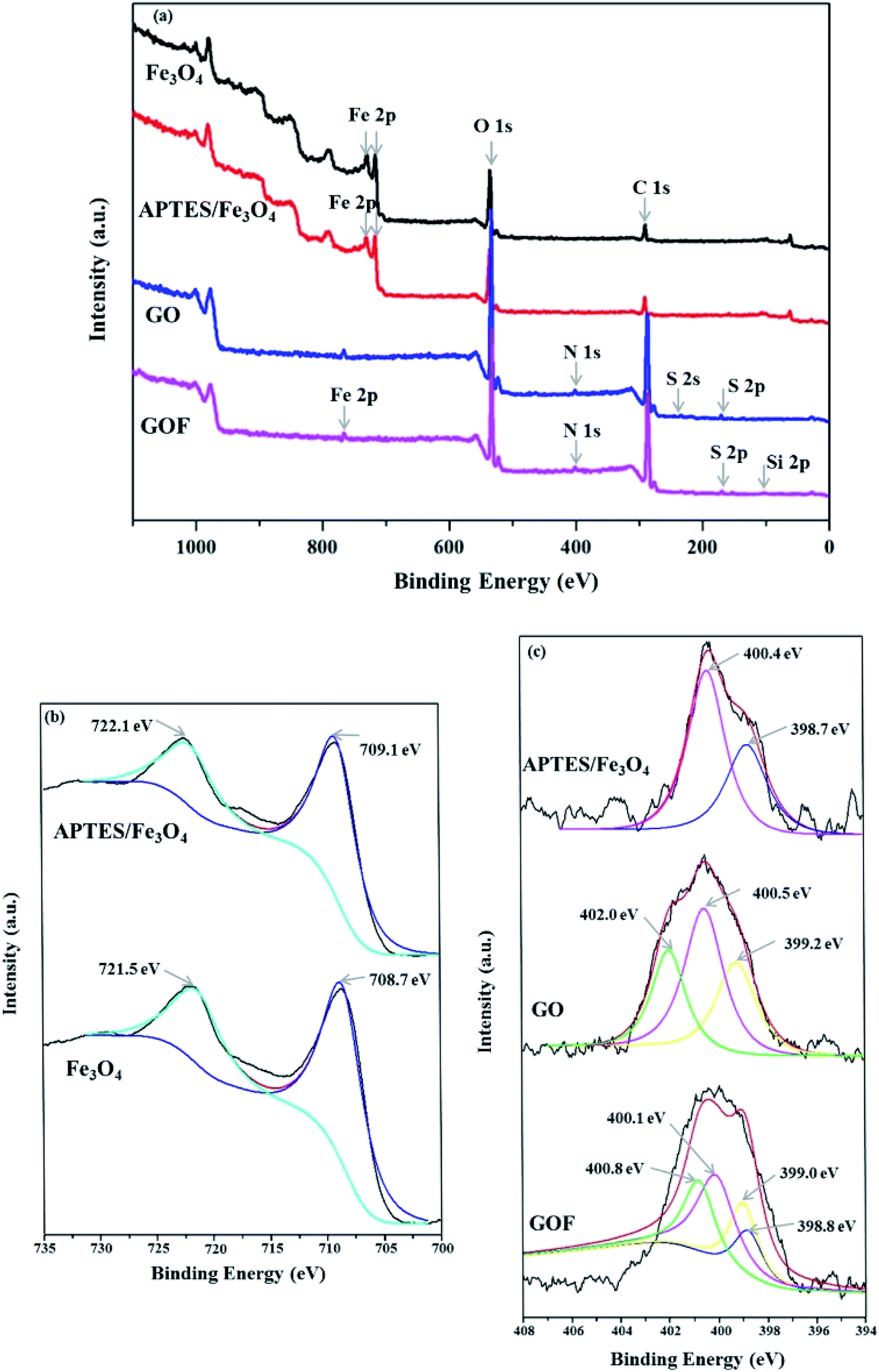 | ||
| Fig. 1 XPS spectra of the samples. (a) XPS survey spectra of Fe3O4, APTES/Fe3O4 nanoparticle, GO and GOF dispersions. (b) Fe 2p of Fe3O4 and APTES/Fe3O4. (c) N 1s of APTES/Fe3O4 nanoparticle, GO and GOF dispersions. | ||
The morphologies of Fe3O4 before and after being modified by APTES were characterized by TEM respectively, as shown in Fig. 2. From the TEM image of the pure Fe3O4 (Fig. 2(b)), the aggregation behavior of the as-prepared Fe3O4 nanoparticles appeared in the spheroid shape could be observed with a mean particle size of 9.6 nm and rough surface. This aggregated phenomenon was usually inevitable during chemical co-precipitation processes owing to the strong intermolecular forces, hydrogen bonds and electrostatic interactions between nanoparticles. Compared with the pure Fe3O4, the APTES/Fe3O4 nanoparticles exhibited the good morphological features of spherical morphology, smooth surface and narrow size distribution, which would prevent the blockage of spinneret hole during spinning when the nanoparticles are grafted on GO. The average particle diameter slightly increased from 9.6 nm for the pure Fe3O4 microspheres to 10.1 nm for the APTES/Fe3O4 nanoparticles (inset in Fig. 2(a) and (b)). The above results indicated that the APTES was encapsulated in the magnetic nanoparticle Fe3O4 during preparation.
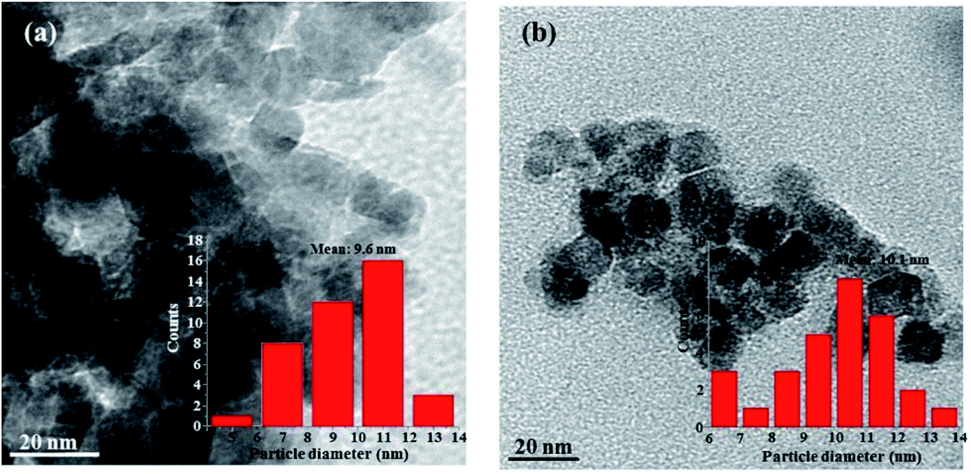 | ||
| Fig. 2 TEM microstructures of Fe3O4 (a) and APTES/Fe3O4 (b) nanoparticles. The inset column figures show the particle size distribution of Fe3O4 and APTES/Fe3O4 nanoparticles. | ||
3.2 Morphology of GO and GOF in an external magnetic field
In order to investigate the evolution of texture of GO and GOF liquid crystals under an external magnetic field (H, 0.31 T), GO and GOF aqueous dispersions were observed by POM between crossed polarizers, as shown in Fig. 3. It can be seen from Fig. 3(a) that the morphology of GO prepared by Hummer's method was irregular. Because of the weak magnetism of the bare GO, the well-aligned alternating ordered structures were difficult to observe under an external magnetic field,22 as shown in Fig. 3(b). However, the textures of GO functionalized with APTES/Fe3O4 nanoparticles, i.e., GOF, turned into the well-aligned, vivid bands within several seconds under the same strength of magnetic field, as shown in Fig. 3(c) and (d). It indicated that magnetic alignment could be remarkably enhanced by decorating graphene oxide with magnetic nanoparticles.23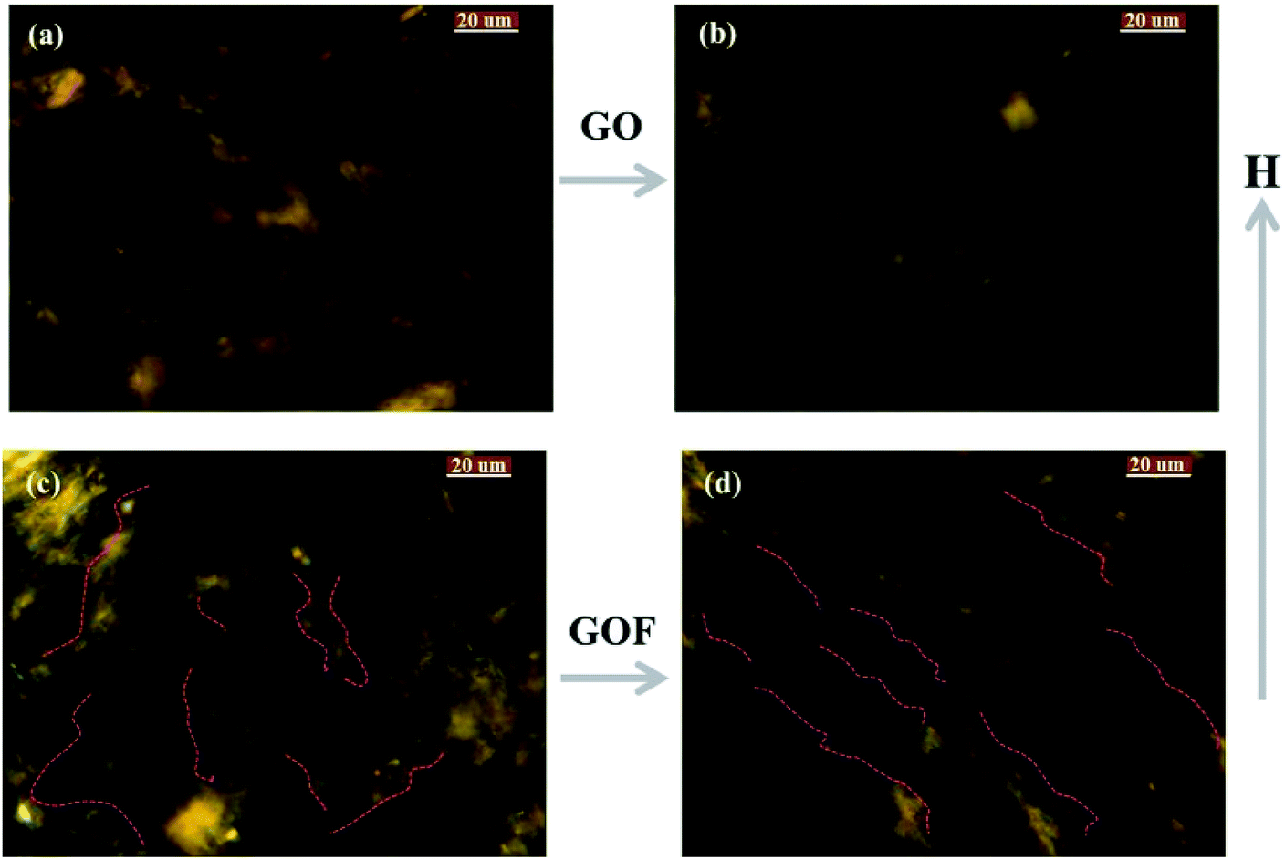 | ||
| Fig. 3 POM observations of GO and GOF dispersions from the absence of a magnetic field to an external magnetic field. (a) and (b) represent the images of GO dispersions without and with a magnetic field, respectively. (c) and (d) represent the images of GOF dispersions without and with a magnetic field, respectively. H is the direction of magnetic field. The pink denotes the magnetic-field-induced alignment. | ||
To understand the morphological details of GO and GOF without and with an external magnetic field, we investigated their structural evolution via TEM experiments, as shown in Fig. 4. In the absence of magnetic field, it can be seen from Fig. 4 that the GO sheets showed the multi-layer fold, and with introduction of APTES/Fe3O4 nanoparticles, the surface of GOF exhibited the curled and rippled structures between nanoparticles. The formation mechanism of irregular wrinkles in GO sheets could be theoretically explained based on elastic plate theory.24,25 It is well documented in several studies that the morphology of GO sheets might be a significant influence by intrinsic ‘‘edge’’ stresses, which can lead to warping and rippling of graphene sheets.24,26,27
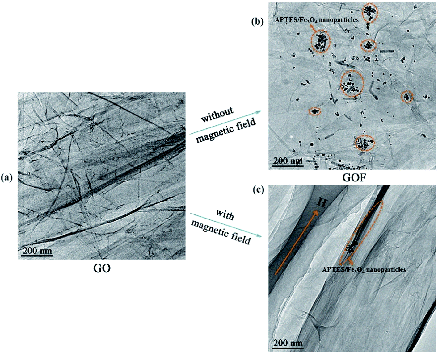 | ||
| Fig. 4 TEM images of the GO and GOF in the absence/presence of magnetic field. (a) is GO nanosheets in the absence of magnetic field. (b) and (c) are GOF nanosheets without and with magnetic field, respectively. Black deposits in (b) and (c) are the APTES/Fe3O4 nanoparticles. H denotes the magnetic field intensity. | ||
As shown in Fig. 4, it is noticed that the modified APTES/Fe3O4 nanoparticles preferentially grow at the edges of GOF, due to the lack of dangling bonds or functional groups on the GOF sheets.28–30 The morphologies of GOF sheets were distinct from the observed GO due to tensile edge stresses at these reconstructed edges, the deformation of the sheets by partially or fully decorating the edges can be explained using the continuum models.31 The deformation of curled sheets can be descripted by the radius of curvature (R0) as follows:
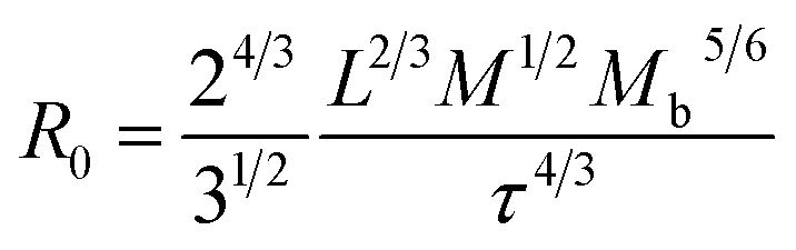 | (1) |
 , L is the sheets width, τ denotes the edge stress. It can be seen that the curvature scale inverse correlation with the sheets width L, which might lead to the different curled and rippled structures in GOF sheets decorated by APTES/Fe3O4 nanoparticles compared with the GO sheets. Moreover, in the GOF system (without a magnetic field), there are three kinds of dominant interactions between GOF sheets, between APTES/Fe3O4 nanoparticles and between GOF sheets and APTES/Fe3O4 nanoparticles, including hydrogen bonds and van der Waals interaction and covalent bonds.32 Additionally, the different geometry of GOF sheets would change the gap between the highest occupied molecular orbital (HOMO) and the lowest unoccupied molecular orbital (LUMO), which might further affect their electromechanical properties.33
However, in the presence of a magnetic field, it is obvious that the GOF layers with highly ordered structure was aligned parallel along the direction of the magnetic field, and the magnetic-particle attaching to the GOF could be observed (see Fig. 4(c)). The images confirmed that the high orientation of GOF layers was being achieved in the presence of external magnetic field. In order to explore the orientation mechanism of GOF by application of a magnetic field, the phenomenon of the well-aligned alternating ordered structures observed in Fig. 4 can be described by self-assembly theory of magnetic-field induction.34–36 The modified APTES/Fe3O4 nanoparticle becomes equivalent magnetic doublet under magnetic field induction, which forms the directional induction force along the external-field direction. The GOF sheets could be aligned along the direction of the easily magnetized axle under an external magnetic field. According to the theory of molecular field, the main driving forces generate by directional wrinkle are the magnetic force of magnetic field to APTES/Fe3O4 nanoparticles and the interaction between magnetic doublets. The magnetic force acting on the APTES/Fe3O4 nanoparticles under conditions of different magnetic intensities can be written as:37
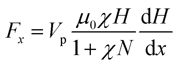 | (2) |
3.3 The GO-based fibers and films through magnetic induced self-assembly
Based on the importance of the external magnetic field induction technique in the preparation of ordered materials, several experiments of the preparation of GOF fibers and GOF films were performed in different magnetic field intensity. The microstructural changes of these fibers were studied by means of SEM, as shown in Fig. 5. It is displayed that the morphologies of RGO layers gradually change from disordered to order, wherein loosely aggregated, semi-ordered lamellae of RGOF sheets are stretched to the final, highly oriented structure of MRGOF through controlling the magnetic field intensity. To be specific, in the absence of magnetic field, GO fiber showed a poplar bark surface with a few large wrinkles due to intrinsic ‘‘edge’’ stresses of GO. When an external magnetic field is exerted, the graphene nanosheets with magnetic precipitates which underwent shrinkage in the radial direction and the interior graphene sheets aligned along the direction of the magnetic field. For example, the surface of the RGOF fiber became more compact and uniform under the influence of compressive edge stresses, as shown the middle image in Fig. 5. Subsequently, with an increasing magnetic field strength, some graphene sheets would move closer towards each other and gradually form thicker macro visible bundles, shown as the right image in Fig. 5, leading to the observed coarsening effect. Moreover, it can also be seen from Fig. 5 that the MRGOF fiber was much more curved compared to the wider sheet considered in RGOF fiber, and the value of fiber diameter decreased from 203 μm in RGO fiber, 191 μm in RGOF fiber to 96.1 μm in MRGOF fiber. According to the above theoretical analysis discussed in Section 3.2, the curvature increases with decreasing width, which was confirmed by morphologies of MRGOF fiber and RGOF fiber.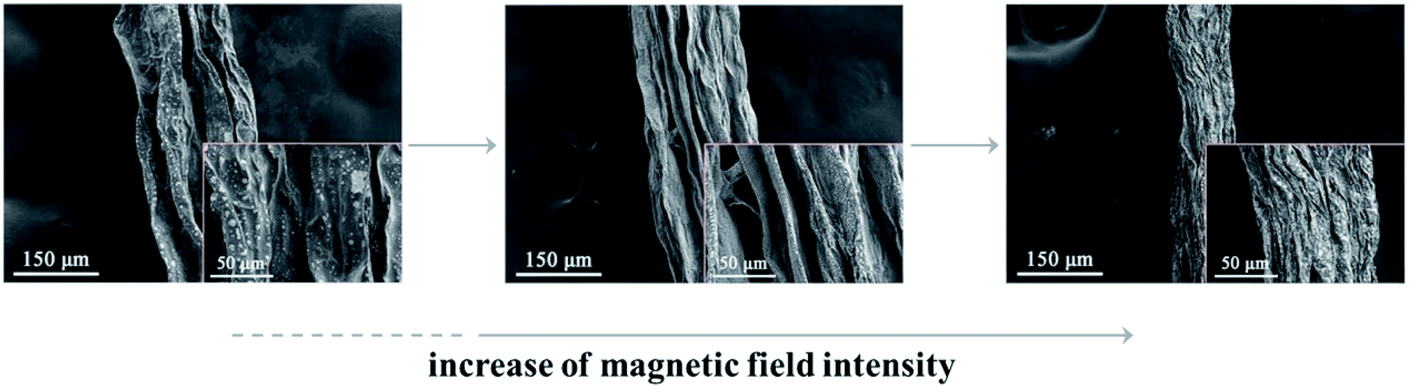 | ||
| Fig. 5 SEM images of the RGO fiber (left), RGOF fiber (center) and MRGOF fiber (right) with an increasing magnetic field strength. | ||
The SEM images of the RGO and RGOF films after applying the different magnetic field strength were shown in Fig. 6. A similar phenomenon was also observed in the RGO, RGOF and MRGOF films compared with the fibers in Fig. 5, where the disordered structure gradually shifts to the well-aligned alternating ordered one, as shown in Fig. 6. The increasing magnetic field strength would cause the relatively rapid movement of APTES/Fe3O4 nanoparticles, leading to much more directional wrinkles (orange in Fig. 6), which suggested that the magnetic field force determined the aligning speed and supported by the above TEM results. It indicated that the assembly of GO sheets in an external magnetic field would be beneficial to offer a versatile route to manipulate the microstructures and the corresponding properties of the carbon-based materials.
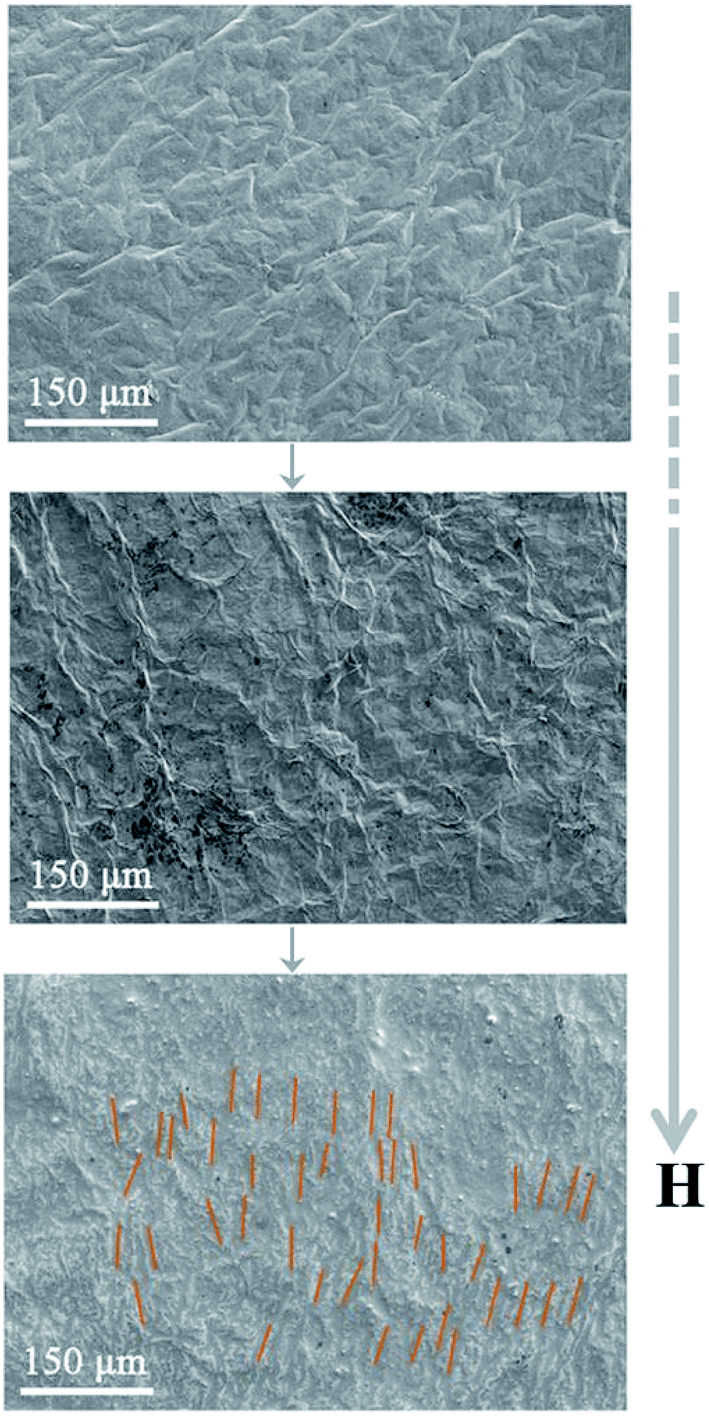 | ||
| Fig. 6 SEM photographs of the RGO film (top), RGOF film (middle) and MRGOF film (bottom) with an increasing magnetic field strength. Orange denotes the aligned direction. | ||
4. Conclusions
In this work, we proposed and demonstrated the highly orientation alignment of GO grafted with the GOF by the application of external magnetic field. The results indicated that the morphologies of GO changed from the disordered, semi-ordered structure to the final, highly oriented wrinkled structure. The orientation mechanism of GO demonstrated that the geometric features of the wrinkles in GO sheets were related to the edge stresses and the elastic stiffness of the sheets, magnetic force of magnetic field to magnetic-particles. Based on the above experimental and theoretical results, we prepared graphene fibers and films using self-assembly of magnetic-field inducement. It was also confirmed that the graphene nanosheets with magnetic precipitates underwent shrinkage in the radial direction with an increasing of magnetic field strength and the interior graphene nanosheets aligned along the direction of the magnetic field, which was in good correspondence with the proposed theories. The present investigations provide useful insights into understanding the wrinkle formation mechanism of graphene nanosheets from pure GO sheets to GOF sheets induced by an external magnetic field, and pave the way for the next generation high-performance graphene electrodes.Conflicts of interest
There are no conflicts to declare.Acknowledgements
We gratefully acknowledge the financial support from the National Natural Science Foundation of China (51703079 and 61704068), the National Training Programs of Innovation and Entrepreneurship for Undergraduates (201710354004 and 201710354005), the Research Program of Zhejiang Educational Committee (Y201738106) and scientific research allowance of Jiaxing University (70518016).References
- K. Gopalsamy, Z. Xu, B. Zheng, T. Huang, L. Kou, X. Zhao and C. Gao, Nanoscale, 2014, 6, 8595–8600 RSC.
- T. Huang, B. Zheng, L. Kou, K. Gopalsamy, Z. Xu, C. Gao, Y. Meng and Z. Wei, RSC Adv., 2013, 3, 23957 RSC.
- T. Xu, Q. Han, Z. Cheng, J. Zhang and L. Qu, Small Methods, 2018, 2, 1800108 CrossRef.
- B. Zheng, T. Huang, L. Kou, X. Zhao, K. Gopalsamy and C. Gao, J. Mater. Chem. A, 2014, 2, 9736–9743 RSC.
- X. Zhao, B. Zheng, T. Huang and C. Gao, Nanoscale, 2015, 7, 9399–9404 RSC.
- A. Fasolino, J. H. Los and M. I. Katsnelson, Nat. Mater., 2007, 6, 858 CrossRef CAS PubMed.
- J. C. Meyer, A. K. Geim, M. I. Katsnelson, K. S. Novoselov, T. J. Booth and S. Roth, Nature, 2007, 446, 60 CrossRef CAS PubMed.
- Q. Li, Z. Li, M. Chen and Y. Fang, Nano Lett., 2009, 9, 2129–2132 CrossRef CAS PubMed.
- Z. Xu and C. Gao, Mater. Today, 2015, 18, 480–492 CrossRef CAS.
- H. Yang, Z. Li, B. Lu, J. Gao, X. Jin, G. Sun, G. Zhang, P. Zhang and L. Qu, ACS Nano, 2018, 12, 11407–11416 CrossRef CAS PubMed.
- P. Zhang, J. Li, L. Lv, Y. Zhao and L. Qu, ACS Nano, 2017, 11, 5087–5093 CrossRef CAS PubMed.
- J. Nilsson, A. H. Castro Neto, F. Guinea and N. M. R. Peres, Phys. Rev. B: Condens. Matter Mater. Phys., 2007, 76, 165416 CrossRef.
- J. Nilsson, A. H. Castro Neto, F. Guinea and N. M. R. Peres, Phys. Rev. B: Condens. Matter Mater. Phys., 2008, 78, 045405 CrossRef.
- J. Sabio, J. Nilsson and A. H. Castro Neto, Phys. Rev. B: Condens. Matter Mater. Phys., 2008, 78, 075410 CrossRef.
- B. Vigolo, A. Pénicaud, C. Coulon, C. Sauder, R. Pailler, C. Journet, P. Bernier and P. Poulin, Science, 2000, 290, 1331 CrossRef CAS PubMed.
- Y.-F. Zhu, C. Ma, W. Zhang, R.-P. Zhang, N. Koratkar and J. Liang, J. Appl. Phys., 2009, 105, 054319 CrossRef.
- R. Sen, B. Zhao, D. Perea, M. E. Itkis, H. Hu, J. Love, E. Bekyarova and R. C. Haddon, Nano Lett., 2004, 4, 459–464 CrossRef CAS.
- J. E. Kim, T. H. Han, S. H. Lee, J. Y. Kim, C. W. Ahn, J. M. Yun and S. O. Kim, Angew. Chem., Int. Ed. Engl., 2011, 50, 3043–3047 CrossRef CAS PubMed.
- W. S. Hummers and R. E. Offeman, J. Am. Chem. Soc., 1958, 80, 1339 CrossRef CAS.
- N. S. McIntyre and D. G. Zetaruk, Anal. Chem., 1977, 49, 1521–1529 CrossRef CAS.
- H. Chen, Y. Li, S. Wang, Y. Li and Y. Zhou, J. Membr. Sci., 2018, 546, 22–30 CrossRef CAS.
- Y. Wang, Y. Huang, Y. Song, X. Zhang, Y. Ma, J. Liang and Y. Chen, Nano Lett., 2009, 9, 220–224 CrossRef CAS PubMed.
- M. Mikhaylova, D. K. Kim, C. C. Berry, A. Zagorodni, M. Toprak, A. S. G. Curtis and M. Muhammed, Chem. Mater., 2004, 16, 2344–2354 CrossRef CAS.
- V. B. Shenoy, C. D. Reddy, A. Ramasubramaniam and Y. W. Zhang, Phys. Rev. Lett., 2008, 101, 245501 CrossRef CAS PubMed.
- L. D. Landau and E. M. Lifshitz, Theory of Elasticity, Oxford, New York, 1986 Search PubMed.
- M. H. Gass, U. Bangert, A. L. Bleloch, P. Wang, R. R. Nair and A. K. Geim, Nat. Nanotechnol., 2008, 3, 676–681 CrossRef CAS PubMed.
- W. H. Duan, K. Gong and Q. Wang, Carbon, 2011, 49, 3107–3112 CrossRef CAS.
- Y. Lu, S. Bangsaruntip, X. Wang, L. Zhang, Y. Nishi and H. Dai, J. Am. Chem. Soc., 2006, 128, 3518–3519 CrossRef CAS PubMed.
- D. B. Farmer and R. G. Gordon, Nano Lett., 2006, 6, 699–703 CrossRef CAS.
- X. Wang, S. M. Tabakman and H. Dai, J. Am. Chem. Soc., 2008, 130, 8152–8153 CrossRef CAS PubMed.
- V. B. Shenoy, C. D. Reddy and Y.-W. Zhang, ACS Nano, 2010, 4, 4840–4844 CrossRef CAS PubMed.
- H. Chen, M. B. Müller, K. J. Gilmore, G. G. Wallace and D. Li, Adv. Mater., 2008, 20, 3557–3561 CrossRef CAS.
- D. Gunlycke, J. Li, J. W. Mintmire and C. T. White, Nano Lett., 2010, 10, 3638–3642 CrossRef CAS PubMed.
- X. Guo, W. Li, L. Luo, Z. Wang, Q. Li, F. Kong, H. Zhang, J. Yang, C. Zhu, Y. Du and J. You, ACS Appl. Mater. Interfaces, 2017, 9, 16581–16593 CrossRef CAS PubMed.
- G. Helgesen, A. T. Skjeltorp, P. M. Mors, R. Botet and R. Jullien, Phys. Rev. Lett., 1988, 61, 1736–1739 CrossRef PubMed.
- J. Ge, L. He, J. Goebl and Y. Yin, J. Am. Chem. Soc., 2009, 131, 3484–3486 CrossRef CAS PubMed.
- R. W. Chantrell, G. N. Coverdale, M. El Hilo and K. O'Grady, J. Magn. Magn. Mater., 1996, 157–158, 250–255 CrossRef.
- C. H. Griffiths, M. P. O'Horo and T. W. Smith, J. Appl. Phys., 1979, 50, 7108–7115 CrossRef CAS.
Footnote |
| † Electronic supplementary information (ESI) available. See DOI: 10.1039/c9ra01807g |
| This journal is © The Royal Society of Chemistry 2019 |