
 Open Access Article
 This Open Access Article is licensed under a Creative Commons Attribution-Non Commercial 3.0 Unported Licence
Development of in situ synthesized Y-based nanoparticle/polyethersulfone adsorptive membranes by adjusting the composition of the coagulation bath for enhanced removal of fluoride†
Anan Cuia,
Fan Nib,
Shihuai Deng*a,
Jinsong He *a,
Fei Shena,
Gang Yanga,
Chun Songa,
Dong Tiana,
Lulu Longa and
Jing Zhanga
*a,
Fei Shena,
Gang Yanga,
Chun Songa,
Dong Tiana,
Lulu Longa and
Jing Zhanga
aInstitute of Ecological and Environmental Sciences, Sichuan Agricultural University, Chengdu, Sichuan 611130, China. E-mail: hejinsong@sicau.edu.cn; shdeng8888@163.com
bDepartment of Chemical Engineering, Northwest University for Nationalities, Lanzhou, Gansu 730030, China
First published on 29th May 2019
Abstract
The effects of the composition of the coagulation bath (NaOH solution) on the preparation of in situ generated Y-based nanoparticles (NPs)/polyethersulfone (PES) composite adsorptive membranes were investigated in terms of membrane structure, composition, surface hydrophilicity, water permeability, phase inversion and adsorption performance for defluoridation for the first time. The changes of NaOH concentration in the coagulation bath altered the membrane structure, which was believed to be associated with the change of the phase inversion kinetics in membrane formation process. With the increase in NaOH concentration of the coagulation bath, the demixing way changed from an instantaneous demixing to a delayed demixing process, which led to the suppression of the formation of macro-voids and the generation of more sponger-like structures. Consequently, the surface porosity and permeability of the resulted membranes decreased, e.g. M2-1 > M2-2 > M2-3 > M2-4. From an over view, the contents of Y-based NPs in nanocomposite membrane matrix decreased with slower phase inversion kinetics. The M10-2 showed the best adsorption performance with the maximum adsorption capacity of 51.058 mg g−1 for fluoride among those prepared membranes, which also contained the most Y-based NPs in membrane. The M10-2 can effectively treat 1770 bed volume of the fluoride contaminated water at neutral pH by continuous filtration, with no leakage of NPs in the permeate. Furthermore, the presence of humic acid and bicarbonate slightly hindered the removal of fluoride in batch and filtration models. This suggested that the prepared in situ nanocomposite adsorptive membranes can be used as a potential membrane for practical treatment of fluoride contaminated water.
1. Introduction
In recent years, nanocomposite membranes have attracted great attention in water and wastewater treatment due to their enhanced properties, such as seawater desalination, adsorption, antifouling, antibacterial, and catalytic ability.1–4 Traditional methods for preparation of nanocomposite membranes usually include blending nanoparticles in casting solution or soaking the membrane in nanoparticle solution.1,5,6 However, these methods generally suffer from the agglomeration of nanoparticles (NPs) during membrane formation process, which would further result in the non-uniform distribution of NPs in nanocomposite membrane and weak compatibility between NPs and membrane matrix.7To solve the shortcomings of the traditional methods, the in situ generation of nanoparticles in membrane is regarded as a powerful strategy by combination of generation of NPs and membrane formation in one step.8,9 In the in situ preparation method, the nanoparticle's precursors can be molecular-level mixed with the casting solution, and in situ generate the NPs in the polymer matrix during the phase inversion process, consequently resulting in an uniform dispersion of the NPs in membrane matrix.7,10
For in situ preparation method, many factors can affect the membrane structure and properties, such as casting solution composition, coagulation bath, temperature and so on.11,12 Among these factors, casting solution composition is one of the most important ones, which is reported to be associated with the changes of thermodynamic instability and viscosity of the casting solution.13,14 Generally, the addition of precursors in casting solution would increase the thermodynamic instability, leading to facilitate a rapid phase inversion process and result in macro-void formation;15 on the contrary, the addition can also cause an increase in viscosity and tends to a delayed demixing process, finally reducing macro-voids.16,17 As a result, the membrane structure and properties are dependent upon the contributions of both thermodynamic enhancement and viscosity inhibition.
On the other hand, the composition of coagulation bath is considered to be another major factor that has significant impacts on membrane structure and properties by adjusting the kinetics of phase inversion process via changing the solvent-non solvent exchange rate.12,18 To study these effects, one of the most common ways is to change the composition of coagulation bath to obtain different mutual affinities with the solvent in casting solutions.19,20 Zhang et al.21 used NaCl as salt coagulation bath (SCB) with different concentration to improve membrane properties and adjust membrane structures. Wang et al.22 investigated the effects of composition of coagulation bath on membrane structure and protein-adsorption-resistant properties of polyethersulfone (PES)/soybean phosphatidylcholine (SPC) membrane. They found that the PC content on membrane surface was significantly affected by the composition of coagulation bath, which could further influence the protein-adsorption-resistant performance.
In our previous study, the in situ generated yttrium-based nanoparticle (NP)/PES composite adsorptive membranes were successfully developed. It has been proved that the composition of casting solution significantly affected the structure and properties of the nanocomposite membranes.23 In addition, our preliminary study had shown that the composition of salt coagulation bath (NaOH solution) could change the in situ generation phase inversion process, resulting in different structure and properties of nanocomposite adsorptive membranes. However, to the best of our knowledge, no research work on the effects of coagulation batch composition on the properties and adsorption ability of nanocomposite adsorptive membranes has been reported by now. Thus, it is very important and interesting to study the fundamental understanding of the in situ preparation process from a new insight view: the correlation between composition of coagulation bath and membrane properties.
In this study, the research work would focus on the effects of composition of coagulation bath on the preparation of in situ-Y-based NPs/PES composite adsorptive membranes. The structure, physic-chemical properties, and adsorption performance of the prepared membranes were studied by adjusting the composition of coagulation bath for the first time. To explore the feasibility of the application of present membranes in treating fluoride-containing water, the batch adsorption and continuous filtration under different conditions were investigated.
2. Material and methods
2.1. Materials
In this study, all the chemicals were of analytical grade and used without further treatment. PES with a molecular weight of 28 KDa was purchased from BASF Co. (Germany). Yttrium(III) nitrate hexahydrate was purchased from Tianjin Kaima Chemical Co., Ltd. Polyvinylpyrrolidone (PVP), 1-methyl-2-pyrrolidone (NMP), sodium hydroxide, sodium fluoride, humic acid (HA) and other chemicals were purchased from Chengdu Kelong Chemical Reagent Plant.2.2. Preparation of Y-based NPs/PES composite adsorptive membrane
The preparation of the nanocomposite adsorptive membranes followed the description in our previous study.23 The compositions of casting solutions and coagulation bath are shown in Table 1.| Membrane | Composition of casting solution | The condition of coagulation bath | ||||
|---|---|---|---|---|---|---|
| PES (wt%) | PVP (wt%) | NMP (wt%) | Y(NO3)3·6H2O (wt%) | NaOH (M) | ||
| M2 | M2-1 | 16 | 3 | 81 | 2 | 0.25 |
| M2-2 | 16 | 3 | 81 | 2 | 0.5 | |
| M2-3 | 16 | 3 | 81 | 2 | 0.75 | |
| M2-4 | 16 | 3 | 81 | 2 | 1 | |
| M6 | M6-1 | 16 | 3 | 81 | 6 | 0.25 |
| M6-2 | 16 | 3 | 81 | 6 | 0.5 | |
| M6-3 | 16 | 3 | 81 | 6 | 0.75 | |
| M6-4 | 16 | 3 | 81 | 6 | 1 | |
| M10 | M10-1 | 16 | 3 | 81 | 10 | 0.25 |
| M10-2 | 16 | 3 | 81 | 10 | 0.5 | |
| M10-3 | 16 | 3 | 81 | 10 | 0.75 | |
| M10-4 | 16 | 3 | 81 | 10 | 1 | |
2.3. Characterization of membranes
 | (1) |
 | (2) |
2.4. Batch adsorption experiments
All the adsorption experiments were carried out in triplicates at room temperature to minimize the experimental errors. The adsorption isotherm experiments were conducted to find out the optimal adsorptive membrane for the fluoride removal. Fluoride solutions with different concentrations in the range of 5–160 mg L−1 were prepared. 0.025 g of each membrane sample was added into 50 mL of different fluoride solutions. The mixed solution was shaken for 48 h with the pH value controlled as a constant of 7.0. Finally, the water sample was collected and the concentration of fluoride was measured by a fluoride electrode (PF-1-01, Leici, China). Meanwhile, the pH effect on the leakage of Y-based NPs was also studied by measuring the Y3+ concentration via an inductively coupled plasma mass spectrometer (ICP-MS, Agilent 7900).The effect of pH on the adsorption of fluoride was studied by varying the solution pH from 3 to 12. The other procedures were the same as the aforementioned.
Adsorption kinetics experiment was conducted by adding 0.5 g of membrane sample into 1 L fluoride solution under continuous stirring. The pH of the fluoride solution was controlled at 7.0. The water samples were collected at different time intervals and the fluoride concentration was measured.
To evaluate the feasibility of the present membrane for defluorination in practical application, the effects of co-existing anions such as NO3−, HCO3−, and SiO32− and natural organic matters (NOMs) on the removal of fluoride at neutral pH were studied. Fluoride solutions with the co-existing substances were prepared. The concentrations of co-existing substances were set referred to their actual concentration levels in natural environment and calculated by the weight of target atoms. The other procedures were the same as the aforementioned.
2.5. Filtration experiments
The filtration experiments with fluoride solution was measured by dead-end filtration method with an ultrafiltration cup (Model 8050, Millipore Corporation), with the pressure of 1.45 psi. The effective area of the membrane M10-2 was 12.56 cm2. The concentration of fluoride solution was around 5 mg L−1 and the solution pH was 7.0. The permeate was collected at different time intervals and analyzed. Besides, the leakage of Y-based NPs in permeate was also studied by ICP-MS (Agilent 7900).The used membrane was desorbed in 200 mL of 0.01 M NaOH solution for 12 h. The regenerated membrane was washed by DI water for several times and subsequently reused for fluoride removal under the same conditions as the aforementioned.
Furthermore, the effects of the above co-existing substances on filtration performance of fluoride were also studied. Fluoride solutions with the co-existing substances were prepared. The other procedures were the same as the aforementioned.
3. Results and discussion
3.1. Characterization of nanocomposite membranes
 | ||
| Fig. 1 The concentrations of Y and O in membrane cross-sections and top surface: Y content in (a) membrane cross-section and (b) top surface; O content in (c) membrane cross-section and (d) top surface. | ||
It should be noted that the measured Y content in obtained membranes is lower than the theoretical Y content in their corresponding casting solutions, which indicates the occurrence of the leaching of Y from polymer bulk into coagulation bath. This finding is consistent with other reported studies.7,29 During the phase inversion process in water environment, the hydrophilic moieties can migrate from the polymer bulk to the interface of water/polymer, and then leach out from surface layer to coagulation bath.22 In this study, the additional positive Y3+ cations easily migrate from polymer bulk to membrane surface and further to coagulation bath in phase inversion process. Simultaneously, the Y3+ cations reacted with OH− anions to in situ form the Y-based NPs in both membrane body and surface, and also in coagulation bath. The changes of the measured content of Y from the generated Y-based NPs suggest that with the increase in NaOH concentration in coagulation bath (e.g. 0.75 M NaOH), more Y3+ cations transfer from the polymer bulk to water/polymer interface and further to coagulation bath, simultaneously reacting with OH− in coagulation bath and forming Y-based NPs.
Furthermore, the distribution of element O in membrane cross-section and surface exhibits the similar trend to that of Y, which should be attributed to the presence of O-containing groups in Y-based NPs. However, the changes of O content are not obvious for all membrane, which is due to the existing large amount of O in the presence of PES membrane body.
Overall, the above results demonstrate that the composition of coagulation bath can significantly affect the composition of in situ NP/PES nanocomposite membranes. In other words, the amount of generated NPs can be controlled by the adjustment of the composition of coagulation bath.
 | ||
| Fig. 2 SEM images and pictures of water contact angle (the inset) of different membranes: (right) top surface and (left) cross section. | ||
The morphologies of membrane cross-sections show that the thickness of different membranes is in the range of 84.5–144.2 μm. All the membranes display a typical asymmetric porous structure, which is composed of a dense top skin layer and a macro-voids sublayer. However, different morphologies of the membranes prepared in different coagulation baths can be found. For example, regular channel-like structure with closed ends is observed in membrane M2-1 prepared under a coagulation bath composition of 0.25 M NaOH. As the concentration of NaOH in coagulation bath increase to 0.5 M and 0.75 M, the channels gradually decrease and more sponge-like structures are observed in membrane M2-2 and M2-3. With the highest concentration of NaOH, the structure changes to small finger, channel and tear-like structures with more sponge-like areas for M2-4. For both M6 and M10 membranes, similar trend can be observed except that more sponge-like structures are observed in membrane structures compared to M2 membranes, especially for M10. In general, with the increase in the NaOH concentration of coagulation bath, the formation of macro-voids is suppressed,30 and more finger- and tear-like structures with more sponge-like areas appear. This phenomenon is believed to be attributed to the kinetics effects during the phase inversion process, which will be discussed next.
Besides, for the membrane structures prepared by different casting solutions under the same coagulation bath composition, e.g., M2-1 vs. M10-1, the number of pores on the membrane surface significantly decreases and the macro-voids in the cross-section are suppressed for M10-1 compared to M2-1. The changes should be ascribed to the delayed demixing rate caused by viscosity hindrance during the phase inversion process, which was deeply discussed in our previous study.23
 | ||
| Fig. 3 Light transmittance curves of different casting solutions in different coagulation bath: (a) M2, (b) M6 and (c) M10 in different coagulation bath. | ||
Moreover, in comparison of the phase inversion process of M2, M6 and M10, M2 completes the phase inversion within 2–3 s, and M6 completes the process for 2.5–3.5 s, while M10 takes a relatively longer time about 6–7 s. This phenomenon is consistent with our previous study, which is caused by the different amount of additional Y precursor in casting solution.23
As illustrated in Section 3.1.4, for different types of membranes, e.g. M2, M6 and M10, with the increase in NaOH concentration of coagulation bath, the demixing rate becomes slower. This leads to the reduction in pores onto the top surface, suppression of the macrovoids formation and facilitation of the formation of finger- and tear-like pores with more sponge-like areas in membrane cross-sections. This phenomenon is consistent with other reported study.21 Compared to M2 and M6, M10 membranes from M10-1 to M10-4 possess much less surface pores and macrovoids with more sponger-like structures, which is attributed to the much slower demixing processes than those for M2 and M6.
On the other hand, as the demixing process becomes slower, the phase inversion process takes longer time. Thus, the additional hydrophilic Y3+ cations in casting solution have more time to migrate from the PES bulk to the interface of water/PES, and then leach out from surface layer to coagulation bath. Simultaneously, the in situ formed small Y-based NPs onto the membrane surface may have more chances to leach into the coagulation bath. Therefore, from an overall view, the contents of Y in membranes shown in Fig. 1 quite match the results of demixing process.
Generally, the membrane structure and composition are associated with the composition of coagulation bath. This implies that the membrane structure and composition and even the adsorption performance can be manipulated by adjusting coagulation bath composition.
| Membrane | Porosity (%) | Water contact angle (°) | Pure water flux (L m−2 h−1) | Thickness (μm) |
|---|---|---|---|---|
| M2-1 | 84.75 | 65.29 ± 0.1 | 112.35 ± 1.0 | 140.7 |
| M2-2 | 82.78 | 66.6 ± 0.5 | 106.53 ± 1.5 | 137.7 |
| M2-3 | 78.15 | 67.28 ± 0.6 | 100.12 ± 0.9 | 84.51 |
| M2-4 | 71.53 | 68.73 ± 0.4 | 87.19 ± 2.1 | 92.23 |
| M6-1 | 83.79 | 55.02 ± 0.1 | 119.09 ± 1.6 | 102.4 |
| M6-2 | 82.37 | 57.14 ± 0.6 | 115.54 ± 1.2 | 112.1 |
| M6-3 | 74.55 | 58.61 ± 0.1 | 93.57 ± 1.0 | 111.3 |
| M6-4 | 68.96 | 60.13 ± 0.9 | 80.32 ± 0.8 | 90.72 |
| M10-1 | 81.69 | 61.23 ± 0.4 | 102.43 ± 1.8 | 110.3 |
| M10-2 | 80.54 | 61.37 ± 0.8 | 98.52 ± 1.6 | 88.57 |
| M10-3 | 70.59 | 62.79 ± 0.1 | 84.203 ± 2.1 | 100 |
| M10-4 | 62.61 | 63.11 ± 1.6 | 71.12 ± 1.1 | 144.2 |
In addition, the results of porosity are also summarized in Table 2. For M2, M6 and M10, the porosity of the membranes decreases with the increase in NaOH concentration, especially for membranes prepared under higher NaOH concentration, e.g., 0.75 M and 1.0 M. As shown in Fig. 2, the macrovoids are suppressed and more sponger-like structure are formed with the increasing NaOH concentration, thereby the corresponding porosity decreases.
As known, the porosity is the main driving force of the water permeability. The WF of different membranes presented in Table 2 shows that the WF decreases with the increase in NaOH concentration, e.g., M2-1 > M2-2 > M2-3 > M2-4, which is quite in agreement with the changes in membrane porosity.
3.2. Adsorption performance
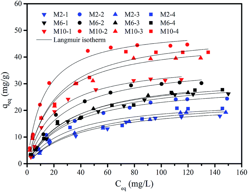 | ||
| Fig. 4 Adsorption isotherm of F− by different membranes. Experimental conditions: m = 0.5 g L−1, pH = 7.0 ± 0.1, reaction time = 48 h, and T = 20 ± 1 °C. | ||
Furthermore, considering the same coagulation bath, the membrane which contains a higher content of Y precursor in casting solution such as M10-2 shows higher adsorption capacity of fluoride than that contains a lower content of Y precursor, such as M2-2. This is mainly due to the higher content of generated Y-based NPs in obtained membrane caused by the higher content of Y precursor in casting solution,23 which is quite consistent with our previous study.
Both Langmuir and Freundlich isotherms models are used to describe the adsorption isotherm data. The Langmuir equation is expressed as follows:
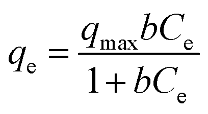 | (3) |
The Freundlich equation is described as below:
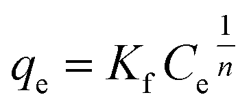 | (4) |
The parameters of Langmuir and Freundlich models are summarized in Table 3. Both Langmuir and Freundlich models can describe the sorption data well, with the value of correlation coefficient (r2) ranging from 0.937 to 0.995 for Langmuir model, and 0.887 to 0.971 for Freundlich model, respectively. While in comparison with the qmax values obtained from both models under the studied concentrations, the data from Langmuir model is more closed to the experimental data than Freundlich model (qmax value not shown). This result indicates that Langmuir model is more suitable for the description of the experimental data than Freundlich model. Thus, the adsorption of F− ions onto the membranes would belong to a monolayer adsorption process. Furthermore, the changes of the value of b show a similar tendency to the changes in Y-based NPs content in membranes. More specifically, a higher content of Y-based NPs in membranes has a higher value of b, leading to a higher adsorption affinity toward fluoride, i.e., M10-2 vs. M10-1.
| Membranes | Langmuir isotherm | Freundlich isotherm | ||||||
|---|---|---|---|---|---|---|---|---|
| qmax (mg g−1) | b (L mg−1) | r2 | χ2 | Kf | n | r2 | χ2 | |
| M2-1 | 23.483 | 0.0247 | 0.986 | 0.437 | 1.939 | 2.155 | 0.971 | 0.929 |
| M2-2 | 30.365 | 0.0312 | 0.990 | 0.621 | 2.969 | 2.273 | 0.944 | 3.654 |
| M2-3 | 24.924 | 0.0242 | 0.982 | 0.696 | 1.979 | 2.123 | 0.968 | 1.203 |
| M2-4 | 24.354 | 0.0322 | 0.937 | 2.545 | 2.485 | 2.298 | 0.953 | 1.911 |
| M6-1 | 32.830 | 0.0293 | 0.995 | 0.357 | 3.187 | 2.283 | 0.968 | 2.418 |
| M6-2 | 38.041 | 0.0365 | 0.989 | 1.209 | 4.078 | 2.309 | 0.927 | 8.084 |
| M6-3 | 34.340 | 0.0297 | 0.992 | 0.581 | 2.976 | 2.132 | 0.964 | 2.887 |
| M6-4 | 33.354 | 0.0318 | 0.983 | 1.357 | 3.366 | 2.299 | 0.969 | 2.512 |
| M10-1 | 38.455 | 0.0454 | 0.988 | 1.378 | 5.043 | 2.463 | 0.914 | 10.412 |
| M10-2 | 51.058 | 0.0798 | 0.988 | 2.726 | 9.857 | 2.967 | 0.887 | 27.208 |
| M10-3 | 46.874 | 0.0492 | 0.986 | 2.368 | 6.776 | 2.618 | 0.955 | 7.710 |
| M10-4 | 49.949 | 0.0459 | 0.980 | 3.812 | 7.068 | 2.618 | 0.950 | 9.604 |
According to the Langmuir model, the maximum adsorption capacity of fluoride is 30.365 mg g−1 for M2-2, 38.041 mg g−1 for M6-2, and 51.058 mg g−1 for M10-2, respectively. Due to the highest adsorption capacity, the M10-2 was used in the subsequent experiments.
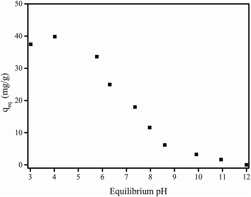 | ||
| Fig. 5 Effect of equilibrium pH on adsorption of F− by membrane M10-2. Experimental conditions: m = 0.5 g L−1, initial F− concentration = 21.26 mg L−1, and T = 20 ± 1 °C. | ||
As demonstrated in Table S1,† the atom content of O decreased after the adsorption of F−, suggesting that the O-containing groups would be involved in the adsorption process. In particular, the high resolution XPS spectra of O 1s shown in Fig. S2† illustrated that after adsorption of F−, the Y–OH content obviously decreased compared to that before adsorption, indicating the association with the ion-exchange process between the fluoride and –OH groups bond to yttrium in the presence of in situ formed Y-based NPs in membrane matrix.23 With the increase in solution pH, more OH− anions exist in the solution and inhibit the ion exchange process between –OH groups and F− anions, reducing the adsorption of F−. At higher pH condition such as pH of 12, the adsorption of F− can be entirely restrained. Since the natural water is generally in the range of 6–8, considering the stability of Y-based NPs in membrane the pH of the subsequent experiments was set as 7.0.
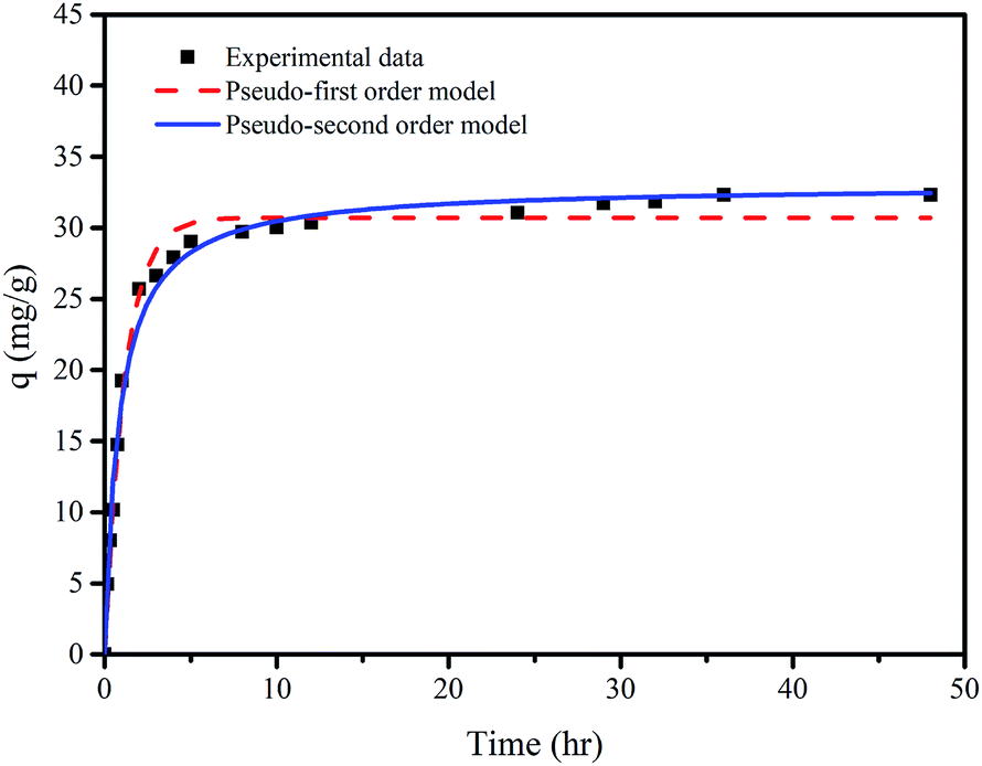 | ||
| Fig. 6 Adsorption kinetics of F− on membrane M10-2: experimental data and pseudo-first order and pseudo-second order models. Experimental conditions: m = 0.5 g L−1, pH = 7.0 ± 0.1, and T = 20 ± 1 °C. | ||
Both pseudo-first order model and pseudo-second order model are used to analyze the experimental data of the adsorption kinetics. The equation of each model is expressed as follows:
| qt = qe(1 − e−k1t) | (5) |
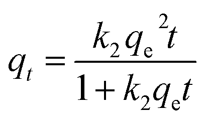 | (6) |
It can be seen that the experimental data can be well fit by both models from Fig. 6. The parameters of both models summarized in Table 4 show that the correlation coefficient (r2) of the pseudo-second order model is slightly higher than that of pseudo-first order model, implying that the adsorption of fluoride onto the M10-2 is controlled by chemisorptions.39
| qexp (mg g−1) | Pseudo-first order model | Pseudo-second order model | ||||
|---|---|---|---|---|---|---|
| qe (mg g−1) | k1 (h−1) | r2 | qe (mg g−1) | k2 ((g mg−1) h−1) | r2 | |
| 32.32 | 30.717 | 0.871 | 0.988 | 33.018 | 0.036 | 0.990 |
The results shown in Fig. 7 demonstrate that the removal rate of fluoride by the membrane is decreased with the increase in fluoride concentration. The presence of nitrate and silicate has limited effects on the removal rate of fluoride. The presence of 0–10 mM bicarbonate decreased the removal rate from 50.1% to 38.5% for 5 mg L−1 F−, 42.1% to 33.2% for 10 mg L−1 F−, and 37.4% to 30.1% for 20 mg L−1 F−, respectively. Overall, the removal rate is reduced by 20–23% for these three concentration levels of fluoride. This result indicates the slight inhibition of bicarbonate on the fluoride removal. Moreover, it seems that when the bicarbonate concentration is above 6 mM, the removal rate reaches a platform without further inhibition effect. Thus, the presence of 6 mM bicarbonate was selected as represented in the following filtration study. For HA, the removal rate is reduced significantly in the presence of 2 mg L−1 HA, while slightly decreased with further increase in HA concentration. Generally, the presence of HA in the range of 2–10 mg L−1 reduces the removal rate of fluoride by 27–33% at the fluoride concentration level of 5 mg L−1 −20 mg L−1.
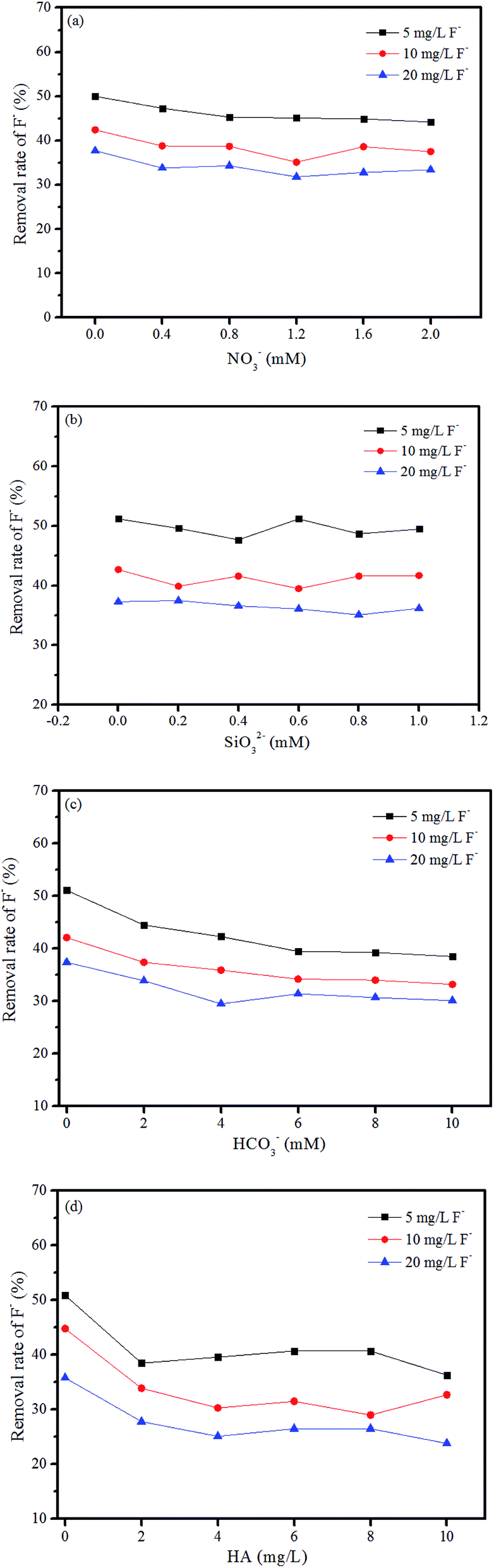 | ||
| Fig. 7 The effects of co-substances on the removal rate of F−: (a) NO3−, (b) SiO32−, (c) HCO3−, and (d) HA. Experimental conditions: m = 0.5 g L−1, pH = 7.0 ± 0.1, and T = 20 ± 1 °C. | ||
3.3. Filtration performance
Fig. 8 shows the fluoride concentration of the permeate is below the maximum contaminant level (MCL, 1.5 ppm) in the first 115 bed volume for single fluoride-containing water. The filtration was continued until the fluoride concentration of permeate reached a constant value, and a total volume of 1770 bed volume of permeate was produced. The corresponding adsorption capacity is 5.99 mg g−1, which is slightly higher than that in batch adsorption, e.g., 5.67 mg g−1. The membrane can yield a total volume of treated water of 366.5 L m−2 as summarized in Table 5. Considering the MCL of fluoride in drinking water, a yield of 23.9 L m−2 can be produced when treating 5.46 mg L−1 fluoride contaminated water. More importantly, the leaching of Y-based NPs in permeate was measured. The result in Fig. 8 showed that the leakage of Y ions is not detected during the whole filtration process. This phenomenon is quite important for the long-term stability of the prepared membranes under continuous filtration.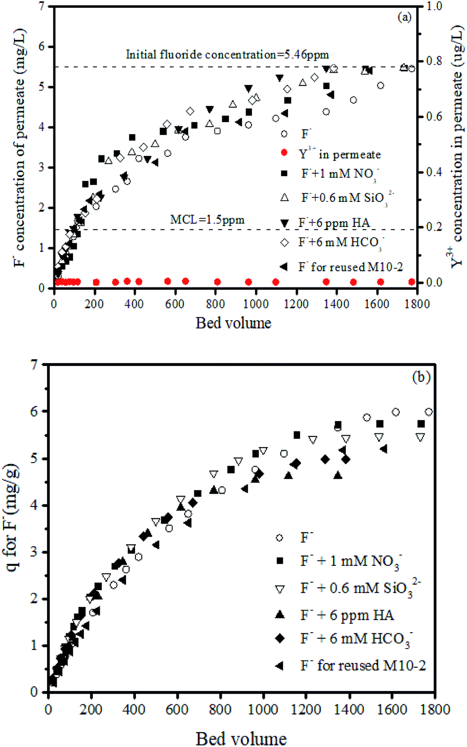 | ||
| Fig. 8 Filtration performance of fluoride with different fluoride-containing influent by M10-2: (a) F− and Y3+ concentrations of permeate vs. bed volume and (b) accumulated q value vs. bed volume. Experimental conditions: pH = 7.0 ± 0.1, initial F− concentration = 5.46 mg L−1, pressure = 1.25 psi. | ||
| Conditions | Bed volume of permeate | Permeate yield (L m−2) | ||
|---|---|---|---|---|
| Conc. under MCL | Conc. reached equilibrium | Conc. under MCL | Conc. reached equilibrium | |
| F− | 115 | 1770 | 23.9 | 366.5 |
| F− + 1 mM NO3− | 135 | 1732 | 27.8 | 358.5 |
| F− + 0.6 mM SiO32− | 130 | 1730 | 27.1 | 358.3 |
| F− + 6 mM HCO3− | 107 | 1347 | 22.3 | 286.6 |
| F− + 6 mg L−1 HA | 96 | 1384 | 19.9 | 278.8 |
| Regenerated M10-2 + F− | 100 | 1563 | 20.8 | 323.6 |
To further confirm the removal of F− by filtration, the composition of used membrane was analyzed by EDS. The EDS mapping results in Fig. 9 clearly show the signal of F element distributed on the membrane cross-section. Besides, the morphology of used membrane does not change obviously, suggesting that the prepared membrane has a good stability under filtration process.
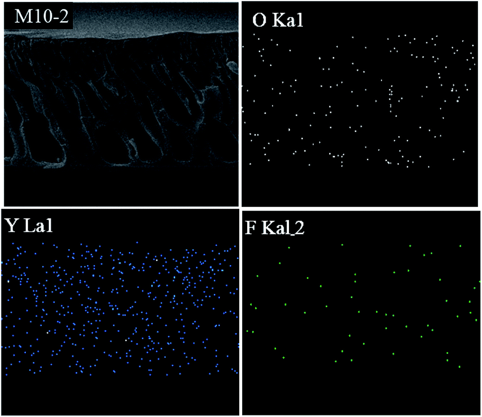 | ||
| Fig. 9 EDS mapping of M10-2 after filtration. | ||
In comparison with other adsorptive membranes for fluoride treatment, the present membrane exhibits a comparable performance with others considering the NPs loading content in membrane matrix.39,40
The reusability of M10-2 is also one concern in this study. The filtration performance by regenerated membrane was also shown in Fig. 8. The total volume of treated permeate is found to be 1563 bed volume, with the corresponding adsorption capacity of 5.20 mg g−1. The used membrane can produce a yield of 323.6 L m−2 totally, which is about 88.3% of that for fresh membrane. This result suggested that the membrane M10-2 has a good reusability and can be reused for fluoride removal. Besides, the value of reusability is lower than that in batch system (97% shown in Fig. S3†). Since the F− may be adsorbed tightly on Y-based NPs loaded in the fine pores in membrane matrix, which would be hardly desorbed in the experimental conditions. Therefore, the available active sites become less in the regenerated membrane, leading to a lower reusability.
Furthermore, Fig. 8 also displays that the presence of nitrate and silicate anions has a very limited effect on the removal of fluoride, whereas the presence of bicarbonate slightly hinder the adsorption of fluoride. The total treated volume of permeate is 1384 bed volume, with the corresponding adsorption capacity of 4.98 mg g−1, about 83.11% of that for pure fluoride influent. This result can be explained by that the Y–OH groups can react with carbonate, forming carbon-oxygen containing complex, reducing the adsorption of fluoride.41,42 It had been confirmed in our previous study that the content of CO32− in the presence of Y-based NPs increased after adsorption of F− in ambient environment as shown in Fig. S2,† indicating that the Y–OH groups can adsorb CO2 from air forming Y-carbonate complex. Thus, when carbonate or bicarbonate anions exist in solution, the active sites of Y–OH would be occupied by these anions leading to less available active sites left for F− adsorption.
Finally, the effect of HA was also investigated. The result shows the presence of 6 mg L−1 HA adversely affected the adsorption of fluoride, reducing the yield by 23.9%, indicating that the membrane fouling caused by HA is not very severe. This phenomenon illustrates that the present Y-based NPs/PES adsorptive membrane could be used as an alternative for the practical treatment of fluoride contaminated water.
4. Conclusions
In this present study, the effects of composition of coagulation bath on membrane structure and properties of the in situ generated Y-based NPs/PES composite adsorptive membranes were studied for the first time. The results illustrated that with the increase in NaOH concentration of coagulation bath, the membrane structure turned to be less pores on top surface and less channel-like macro-voids with more sponger-liked areas in cross-section, leading to a reduction in surface hydrophilicity and water permeability, and the content of Y-based NPs slightly decreased. These changes were related to the change of phase inversion kinetics from an instantaneous demixing to a delayed demixing due to the increase in NaOH concentration. Furthermore, the M10-2 possessed the best adsorption performance of fluoride, with the maximum adsorption capacity of 51.058 mg g−1 at neutral pH. The continuous filtration study indicated that the M10-2 can effectively produce a yield of 23.9 L m−2 when treating 5.46 mg L−1 fluoride-containing water to MCL. The presence of co-existing substances had limited (nitrate and silicate anions) or slight effects (bicarbonate and HA) on the removal of fluoride. More importantly, the membrane was stable in filtration process with no leakage of NPs in permeate, little change in membrane morphology, and a high reusability of 88% for defluorination, suggesting a potential application of the present membrane in the treatment of fluoride-containing water. These findings indicated that the membrane structure and properties can be controlled by adjusting the composition of coagulation bath during the in situ preparation process.Conflicts of interest
There are no conflicts to declare.Acknowledgements
This study was supported by the National Natural Science Foundation of China (grant number 51708372, 51508465), and Key Projects funded by Sichuan Province Education Department (grant number 18ZA0372).References
- A. C. Sun, W. Kosar, Y. Zhang and X. Feng, Desalination, 2013, 309, 156–164 CrossRef CAS.
- J. R. Du, S. Peldszus, P. M. Huck and X. Feng, J. Membr. Sci., 2015, 475, 488–495 CrossRef CAS.
- Y. Tang, N. Li, A. Liu, S. Ding, C. Yi and H. Liu, Desalination, 2012, 287, 326–339 CrossRef CAS.
- M. Kumar, R. Shevate, R. Hilke and K.-V. Peinemann, Chem. Eng. J., 2016, 301, 306–314 CrossRef CAS.
- L. M. Jin, S. L. Yu, W. X. Shi, X. S. Yi, N. Sun, Y. L. Ge and C. Ma, Polymer, 2012, 53, 5295–5303 CrossRef CAS.
- P. Sivaranjana, E. R. Nagarajan, N. Rajini, M. Jawaid and A. V. Rajulu, Int. J. Biol. Macromol., 2017, 99, 223–232 CrossRef CAS PubMed.
- Q. Zhang, L. Fan, Z. Yang, R. Zhang, Y.-n. Liu, M. He, Y. Su and Z. Jiang, Appl. Surf. Sci., 2017, 410, 494–504 CrossRef CAS.
- M. Ben-Sasson, X. Lu, E. Bar-Zeev, K. R. Zodrow, S. Nejati, G. Qi, E. P. Giannelis and M. Elimelech, Water Res., 2014, 62, 260–270 CrossRef CAS PubMed.
- Q. Liu, H. Wang, C. Wu, Z. Wei and H. Wang, Sep. Purif. Technol., 2017, 188, 282–292 CrossRef CAS.
- W. Chen, Y. Su, L. Zhang, Q. Shi, J. Peng and Z. Jiang, J. Membr. Sci., 2010, 348, 75–83 CrossRef CAS.
- H. Liu and X. Liao, Sep. Purif. Technol., 2019, 212, 619–631 CrossRef CAS.
- E. Saljoughi, M. Amirilargani and T. Mohammadi, Desalination, 2010, 262, 72–78 CrossRef CAS.
- A. K. Hołda, B. Aernouts, W. Saeys and I. F. J. Vankelecom, J. Membr. Sci., 2013, 442, 196–205 CrossRef.
- Y. Li, B. Cao and P. Li, J. Membr. Sci., 2017, 544, 1–11 CrossRef CAS.
- X. Zhao, N. Jia, L. Cheng, L. Liu and C. Gao, J. Membr. Sci., 2018, 560, 47–57 CrossRef CAS.
- W.-S. Hung, J.-H. Liang, R. L. G. Lecaros, Q.-F. An, C.-C. Hu, K.-R. Lee and J.-Y. Lai, Sep. Purif. Technol., 2017, 187, 443–452 CrossRef CAS.
- D. Sun, M. Meng, Y. Qiao, Y. Zhao, Y. Yan and C. Li, Sep. Purif. Technol., 2018, 194, 64–72 CrossRef CAS.
- T. V. Plisko, A. V. Bildyukevich, Y. A. Karslyan, A. A. Ovcharova and V. V. Volkov, J. Membr. Sci., 2018, 565, 266–280 CrossRef CAS.
- H. Rajabi, N. Ghaemi, S. S. Madaeni, P. Daraei, B. Astinchap, S. Zinadini and S. H. Razavizadeh, Appl. Surf. Sci., 2015, 349, 66–77 CrossRef CAS.
- X. Zhang, X. Fang, J. Li, S. Pan, X. Sun, J. Shen, W. Han, L. Wang and S. Zhao, J. Colloid Interface Sci., 2018, 514, 760–768 CrossRef CAS PubMed.
- Y. Zhang, X. Tong, B. Zhang, C. Zhang, H. Zhang and Y. Chen, J. Membr. Sci., 2018, 548, 32–41 CrossRef CAS.
- T. Wang, Y.-q. Wang, Y.-l. Su and Z.-y. Jiang, Colloids Surf., B, 2005, 46, 233–239 CrossRef CAS PubMed.
- J. He, A. Cui, F. Ni, S. Deng, F. Shen, C. Song, L. Lou, D. Tian, C. Huang and L. Long, J. Colloid Interface Sci., 2019, 536, 710–721 CrossRef CAS PubMed.
- A. Alpatova, E.-S. Kim, X. Sun, G. Hwang, Y. Liu and M. Gamal El-Din, J. Membr. Sci., 2013, 444, 449–460 CrossRef CAS.
- I. H. Alsohaimi, M. Kumar, M. S. Algamdi, M. A. Khan, K. Nolan and J. Lawler, Chem. Eng. J., 2017, 316, 573–583 CrossRef CAS.
- C. Mbareck, Q. T. Nguyen, O. T. Alaoui and D. Barillier, J. Hazard. Mater., 2009, 171, 93–101 CrossRef CAS PubMed.
- Z. Zhang, Q. An, T. Liu, Y. Zhou, J. Qian and C. Gao, Desalination, 2011, 269, 239–248 CrossRef CAS.
- A. J. Reuvers and C. A. Smolders, J. Membr. Sci., 1987, 34, 67–86 CrossRef CAS.
- S. Han, L. Mao, T. Wu and H. Wang, J. Membr. Sci., 2016, 516, 47–55 CrossRef CAS.
- J. Zhang, Z. Wang, M. Liu, F. Zhao and Z. Wu, J. Membr. Sci., 2017, 526, 272–280 CrossRef CAS.
- Z. Zhang, Q. An, Y. Ji, J. Qian and C. Gao, Desalination, 2010, 260, 43–50 CrossRef CAS.
- B. Jung, J. K. Yoon, B. Kim and H. W. Rhee, J. Membr. Sci., 2004, 243, 45–57 CrossRef CAS.
- C. Dong, G. He, H. Li, R. Zhao, Y. Han and Y. Deng, J. Membr. Sci., 2012, 387–388, 40–47 CrossRef CAS.
- A. L. Ahmad, W. K. W. Ramli, W. J. N. Fernando and W. R. W. Daud, Sep. Purif. Technol., 2012, 88, 11–18 CrossRef CAS.
- S. Zwane, M. L. Masheane, A. T. Kuvarega, G. D. Vilakati, B. B. Mamba, H. Nyoni, S. D. Mhlanga and D. S. Dlamini, Journal of Water Process Engineering, 2017 DOI:10.1016/j.jwpe.2017.09.013.
- Y.-M. Zheng, S.-W. Zou, K. G. N. Nanayakkara, T. Matsuura and J. P. Chen, J. Membr. Sci., 2011, 374, 1–11 CrossRef CAS.
- Y. Yu, L. Yu, M. Sun and J. Paul Chen, J. Colloid Interface Sci., 2016, 474, 216–222 CrossRef CAS PubMed.
- J. Wang, L. Wu, J. Li, D. Tang and G. Zhang, J. Alloys Compd., 2018, 753, 422–432 CrossRef CAS.
- J. He, T. S. Siah and J. Paul Chen, Water Res., 2014, 56, 88–97 CrossRef CAS PubMed.
- S. Karmakar, S. Bhattacharjee and S. De, J. Environ. Chem. Eng., 2017, 5, 6087–6097 CrossRef CAS.
- D. Niu, R. W. Ashcraft and G. N. Parsons, Appl. Phys. Lett., 2002, 80, 3575–3577 CrossRef CAS.
- Y. Kuroda, H. Hamano, T. Mori, Y. Yoshikawa and M. Nagao, Langmuir, 2000, 16, 6937–6947 CrossRef CAS.
Footnote |
| † Electronic supplementary information (ESI) available. See DOI: 10.1039/c9ra01771b |
| This journal is © The Royal Society of Chemistry 2019 |