DOI:
10.1039/C9RA01451A
(Paper)
RSC Adv., 2019,
9, 11932-11938
Three novel polyoxometalate-based inorganic–organic hybrid materials based on 2,6-bis(1,2,4-triazol-1-yl)pyridine†
Received
26th February 2019
, Accepted 1st April 2019
First published on 16th April 2019
Abstract
Three novel inorganic–organic hybrid materials [Co(btp)2(W5O16)(H2O)]n (1), [Cd3(btp)6(PW12O40)2(H2O)6·6H2O]n (2), and [Ag3(btp)2(PMo12O40)·1.5H2O]n (3) (btp = 2,6-bis(1,2,4-triazol-1-yl)pyridine) have been hydrothermally synthesized and characterized by IR spectroscopy, single-crystal X-ray diffraction, powder X-ray diffraction (PXRD), elemental analysis and thermal gravimetric analysis (TGA). The most striking structure feature of compound 1 is a 3D polycatenation framework, interpenetrated by a 2D 4-connected sql topology layer and a 3D 6-connected rob topology framework. Compound 2 exhibits a rare meso-helices 3D network with different chiralities crossing coexistence. Compound 3 also holds a 3D framework formed by linking terminal oxygen atoms of [α-PMo12O40]3− anions and silver ions in a 2D metal–organic layer. Compound 1 displays antiferromagnetic behavior. The luminescence, electrochemical and photocatalytic properties of compounds 1–3 have also been investigated. Compound 3 exhibits significant electrochemical activity for the reduction of H2O2 while compounds 1 and 2 show efficient photocatalytic activities for the degradation of Rhodamine B (RhB). Furthermore, the three compounds display luminescence behaviors in the solid state.
Introduction
Currently, the design and synthesis of new inorganic–organic hybrid materials, especially polyoxometalate (POM)-based compounds modified by different transition-metals (TMs) and organic ligands, have attracted considerable attention, owing to not only the structural diversities but also the potential applications, such as heterogeneous catalysis, selective absorption, electrochemistry, magnetic functional materials,1–4 etc.
On the one hand, POMs, as one type of transition-metal oxide anionic cluster, can be regarded as “building blocks” with their terminal or bridging oxides coordinating with metal cations. On the other hand, POMs are very good candidates in the synthesis of various multifunctional inorganic–organic hybrid materials because of the following characteristics: (i) the chemically-tunable clusters with negative charges and chemical modifications; (ii) having remarkable catalytic properties; (iii) their tuned acidic and redox properties. An effective strategy to synthesize POM-based inorganic–organic hybrid materials is the combination of POMs clusters into the framework built up from functional organic moieties and desired transition metals (TMs) through the self-assembly methods. So far, numerous inorganic–organic hybrid materials have been obtained, which reveal multifunctional characteristics such as electrocatalytic and photocatalytic activities.5,6
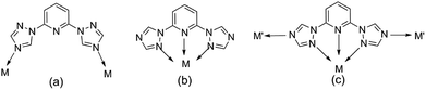
Meanwhile, the choice and design of organic ligands are of great importance for exploring new POM-based inorganic–organic hybrid materials.7–9 Through literature research, many N-heterocyclic organic ligands containing imidazole groups have been used to synthesize POM-based inorganic–organic hybrid materials, such as 1,4-bis(1-imidazoly)benzene, 2,5-bis(1-imidazoly)pyridine, 2,6-bis(1-imidazoly)pyridine.10–13 By comparison, triazoles and its derivatives, because of their potential μ1,2-, μ2,4-, and μ1,2,4-bridging fashions, are expected to construct more novel functional frameworks with intriguing structural motifs. Some flexible ligands containing triazoles by the introduction of –(CH2)n– or phenyl groups have been focused on so as to construct more complicated and variable structural topologies (such as 2,6-bis(1,2,4-triazol-1-yl)benzene, 2,6-bis(1,2,4-triazol-1-yl)ethane, 2,6-bis(1,2,4-triazol-1-yl)propane).14–17 However, the ligand containing pyridine and double-triazole (2,6-bis(1,2,4-triazol-1-yl)pyridine (btp)), has been paid less attention18–20 which has the potential to adopt various coordination modes: (a) bridging two metal centers; (b) chelating a metal ion as a terdentate ligand; (c) functioning in modes A and B simultaneously (Scheme 1).
 |
| | Scheme 1 The potential coordination modes of the ligands. | |
Herein, btp ligand was firstly used to construct three novel POM-based inorganic–organic hybrid materials, namely, [Co(btp)2(W5O16)(H2O)]n (1), [Cd3(btp)6(PW12O40)2(H2O)6·6H2O]n (2), [Ag3(btp)2(PMo12O40)·1.5H2O]n (3). Different structures are discussed, especially compound 1 displays a rare 3D polycatenation framework interpenetrated by a 2D sql layer and a 3D rob network while compound 2 bears one unusual meso-helix 3D network constructed left- and right-helices by the metal centers following different axial directions. Furthermore, the electrocatalysis, luminescence properties of compounds 1–3, photocatalytic properties of compounds 1–3 and the magnetism property of compound 1 are also discussed, respectively.
Experiment section
Materials and methods
All materials were commercially available and used as received without further purification. The FT-IR spectrum was recorded on a Bruker VERTEX-70 FT-IR spectrophotometer in the range of 400–4000 cm−1 using KBr pellet. Elemental analysis was carried out on a Vario EL III Etro Elemental Analyzer. Powder X-ray diffraction (PXRD) was gathered on a Bruker D8 Advance diffractometer with CuKα radiation in the 2θ = 5–50°. Thermogravimetric analysis (TGA) was carried out at room temperature by heating the samples from 25 to 1000 °C under a N2 ambient air with a heating rate of 20 °C min−1 using TGA/DSC3+. Magnetic measurement was carried out on a Quantum Design MPMS-XL SQUID magnetometer.
Synthesis of [Co(btp)2(W5O16)(H2O)]n (1)
A mixture of CoCl2·6H2O (0.3 mmol, 0.071 g), btp (0.2 mmol, 0.042 g), Na2H5P(W2O7)6 (0.05 mmol, 0.148 g), H2O (8 mL) was placed in a Teflon-lined stainless steel vessel, stirred until it was uniformly mixed (about 40 minutes), adjust the pH of the solution to about 2.1 with 2 mol L−1 HCl during the stirring, and kept at 150 °C for 3 days; then cooled to room temperature over 7–8 h, red block crystals of 1 were obtained and washed with H2O (yield: 0.033 g, 39.32% based on Na2H5P(W2O7)6). Anal. calcd (%) for CoW5C18H16N14O17: C, 12.89; H, 0.95; N, 11.70. Found (%): C, 12.88; H, 0.96; N, 11.68. IR (KBr, cm−1): 3426 (w), 1609 (s), 1535 (s), 1468 (s), 1317 (m), 1282 (m), 1222 (m), 1174 (w), 1140 (m), 1107 (w), 977 (vs.), 887 (s), 783 (s).
Synthesis of [Cd3(btp)6(PW12O40)2(H2O)6·6H2O]n (2)
Similar to that of compound 1, except that CdCl2·2.5H2O (0.3 mmol, 0.069 g) was used as the raw material and the mixture was kept in 180 °C, light yellow block crystals of 2 were obtained and washed with H2O (yield: 0.078 g, 30.84% based on btp). Anal. calcd (%) for Cd3P2W24C54H66N42O92: C, 8.56; H, 0.89; N, 7.77. Found (%): C, 8.55; H, 0.88; N, 7.75. IR (KBr, cm−1): 3464 (w), 3130 (w), 1610 (s), 1521 (s), 1476 (m), 1370 (w), 1283 (m), 1218 (m), 1134 (m), 1075 (s), 985 (s), 900 (s), 814 (s).
Synthesis of [Ag3(btp)2(PMo12O40)·1.5H2O]n (3)
Similar to that of compound 1, except that AgNO3 (0.1 mmol, 0.017 g) and H3PMo12O40 (0.05 mmol, 0.091 g) were used as the raw materials, golden yellow block crystals of 3 were obtained and washed with H2O (yield: 0.043 g, 49.63% based on AgNO3). Anal. calcd (%) for Ag3PMo12C18H17N14O41.5: C, 8.33; H, 0.65; N, 7.56. Found (%): C, 8.32; H, 0.66; N, 7.54. IR (KBr, cm−1): 3440 (w), 3120 (w), 1609 (m), 1527 (m), 1460 (m), 1310 (w), 1220 (w), 1171 (w), 1065 (s), 953 (s), 877 (s), 798 (s).
X-ray crystallographic analyses
Single crystal data were collected on Bruker Apex-II CCD area detector diffractometer with graphite-monochromatized MoKα radiation (λ = 0.71073 Å) at room temperature. Data absorption correction and reduction were made with empirical methods. The structures were solved by direct methods with SHELXS-97 (ref. 21) for compounds 2–3 and SHELXS-2014 (ref. 22) for compound 1, respectively, and refined by full matrix least-squares methods on F2 with SHELXL-97 (ref. 23) for compounds 2–3 and SHELXL-2014 (ref. 24) for compound 1, respectively. Anisotropic displacement parameters were refined for all non-hydrogen atoms. Most hydrogen atoms were localized in their calculated positions and refined using a riding model. Crystal data and refinement for compounds 1–3 are listed in the Table S1 (ESI†) and selected bond length (Å) and bond angles (°) in Table S2–S4 (ESI†). CCDC: 1895048–1895050 for compounds 1–3, respectively.
Results and discussion
Crystal structure of compound [Co(btp)2(W5O16)(H2O)]n (1)
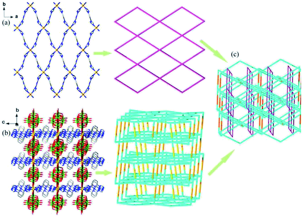
Single-crystal X-ray analysis reveals that compound 1 crystallizes in orthorhombic space group Cccm. Compound 1 exhibits a rare 3D polycatenation framework, which is interpenetrated by a 2D 4-connected sql topology layer and a 3D 6-connected rob network. As shown in Fig. 1, the asymmetrical unit contains two independent Co(II) atoms, bearing six-coordinate octahedral geometrical configuration. Both of Co(II) atoms are ligated by four nitrogen atoms of btp ligands in the equatorial plane (N1, N1B, N1C and N1D for Co1, N2, N2A, N2E and N2F for Co2, A: 0.5 − x, 0.5 − y, z; B: x, 1 − y, 0.5 − z; C: −x, y, 0.5 − z; D: −x, 1 − y, z; E: x, y, −z, F: 0.5 − x, 0.5 − y, −z) with Co–N bond lengths of about 2.066(7) Å, and two oxygen atoms derived from two lattice water molecules (O1W, O1WB for Co1) and the terminal oxygen atoms of two W10O324− anions (O1, O1A for Co2) in the axial positions with the range of Co–O bond lengths about 2.127(7) −2.320 (10) Å.
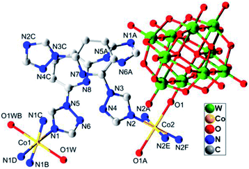 |
| | Fig. 1 The coordination diagram of Co(II) atoms in the compound 1. (Symmetry codes: A: 0.5 − x, 0.5 − y, z; B: x, 1 − y, 0.5 − z; C: −x, y, 0.5 − z; D: −x, 1 − y, z; E: x, y, −z; F: 0.5 − x, 0.5 − y, −z). | |
As a result, Co1 atoms are bridged by four ligands to form one 2D layered structure in the ab plane, while Co2 atoms coordinated by four ligands and the W10O324− anion to construct one 3D framework (Fig. 2a and b). From the view point of topology, if the coordinated water molecules are ignored, the 2D layered structure is regarded as a 4-connected sql layer with {44·62} topology by simplifying the btp ligands as linear connectors and Co1 ions as a 4-connecting nodes. The 3D network can be rationalized as a 6-connected framework with rob topology (point symbol (48·66·8)), in which the Co2 atoms are considered as nodes as well as btp ligands and the W10O324− anions as linkers. It is interesting that the 2D sql motifs and the 3D rob frameworks are further interpenetrated with each other to form one rare 3D(2D/3D) polycatenation framework (Fig. 2c). Some examples of polycatenation arrays formed by interpenetrating with two motifs are known,25–29 including 1D + 2D → 2D arrays, 1D + 2D → 3D arrays, 0D + 2D → 2D arrays and 2D + 2D → 3D arrays. However, the polycatenation framework involving 3D and 2D networks is quite unusual.9,30,31
 |
| | Fig. 2 (a) 2D layered structure and its topological representation in compound 1. (b) 3D network structure and its topological representation in compound 1. (c) The topological representation of the 3D(2D/3D) polycatenation framework. Color scheme: W: green; Co: light orange; O: red; N: blue; C: gray. (The hydrogen atoms and the water molecules are omitted for clarity.) | |
Crystal structure of compound [Cd3(btp)6(PW12O40)2(H2O)6·6H2O]n (2)
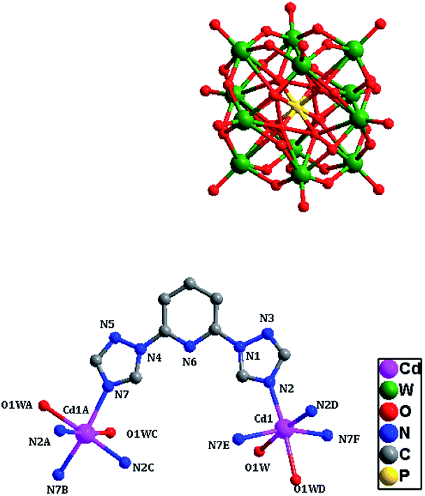
Single-crystal X-ray structural analysis shows that compound 2 belongs to cubic Ia![[3 with combining macron]](https://www.rsc.org/images/entities/char_0033_0304.gif) space group, forming a rare 3D network structure with different meso-helices crossing coexistence. In compound 2, the asymmetrical unit contains one independent Cd(II) atom, which bears six-coordinated environment, ligated by four nitrogen atoms (N2, N2D, N7E and N7F, D: 1 − x, −1/2 − y, z; E: 1 + y, −3/2 − z, −3/2 + x; F: −y, 1 + z, −3/2 + x) from four btp ligands and two oxygen atoms from two coordinated water molecules (Fig. 3). The bond length of Cd–N is 2.30(2)–2.35(3) Å, the Cd–O bond length is 2.44(3) Å, and the bond angles of O–Cd–O, N–Cd–N and N–Cd–O are 84(2)° are 94.7(8)–161.1(12)° and 82.1(9)–173.1(11)°, respectively.
space group, forming a rare 3D network structure with different meso-helices crossing coexistence. In compound 2, the asymmetrical unit contains one independent Cd(II) atom, which bears six-coordinated environment, ligated by four nitrogen atoms (N2, N2D, N7E and N7F, D: 1 − x, −1/2 − y, z; E: 1 + y, −3/2 − z, −3/2 + x; F: −y, 1 + z, −3/2 + x) from four btp ligands and two oxygen atoms from two coordinated water molecules (Fig. 3). The bond length of Cd–N is 2.30(2)–2.35(3) Å, the Cd–O bond length is 2.44(3) Å, and the bond angles of O–Cd–O, N–Cd–N and N–Cd–O are 84(2)° are 94.7(8)–161.1(12)° and 82.1(9)–173.1(11)°, respectively.
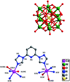 |
| | Fig. 3 The coordination diagram of the Cd(II) atoms in compound 2. (Symmetry codes: A: 3/2 + z, −1 + x, −3/2 − y; B: x, −1 − y, −5/2 − z; C: 3/2 + z, −x, −1 + y; D: 1 − x, −1/2 − y, z; E: 1 + y, −3/2 − z, −3/2 + x; F: −y, 1 + z, −3/2 + x). (The hydrogen atoms and crystal water molecules are omitted for clarity.) | |
Just due to the coordination of Cd–N2 and Cd–N7 (Fig. 4a), the Cd(II) atoms are bridged by the btp ligands to fabricate left- and right-helical chains by 21 screw axis with the pitch of 30.375 Å, which are vertical to each other (Fig. 4b) and have the same components transmitted by the alternately linking sequence of N2–Cd–N2 and N7–Cd–N7. As a result, cross-linked meso-helixes 3D network are constructed by the metal ions following different axial directions (Fig. 4c). As far as we know, the meso-helices with different chiralities crossing coexisting in 3D structure are rare,32,33 which are determined by the high symmetry of compound 2. Meanwhile, two kinds of cavities are formed with [α-PW12O40]3− polyoxoanions filled as “guest” cluster anions through electrostatic interactions (Fig. 4d).
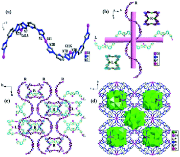 |
| | Fig. 4 (a)–(c) The pseudo-helical chains in compound 2. (Symmetry codes: A: 3/2 + z, −1 + x, −3/2 − y; B: x, −1 − y, −5/2 − z; D: 1 − x, −1/2 − y, z; G: −1/2 − z, 1/2 − x, −3/2 − y; H: 1 − x, 1/2 + y, −5/2 − z). (d) The 3D network of compound 2. The color scheme for (b) and (c): Cd: pink; N: yellow and dark red; C: sky blue and purple. (The hydrogen atoms and crystal water molecules are omitted for clarity.) | |
Crystal structure of compound [Ag3(btp)2(PMo12O40)·1.5H2O]n (3)
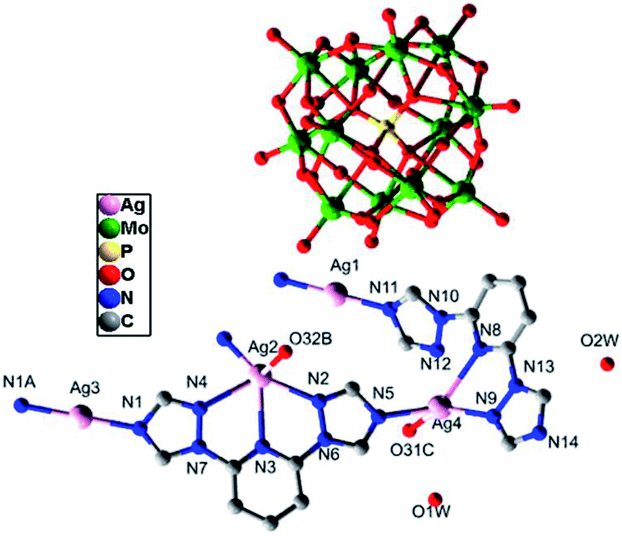
Single-crystal X-ray structural analysis shows that compound 3 belongs to monoclinic P21/n space group, which is a 3D framework formed by Ag–O between 2D metal–organic layers and [α-PMo12O40]3− polyoxoanions. From Fig. 5, the asymmetrical unit of compound 3 contains four Ag(I) atoms. Ag1 and Ag3 atoms bear linear geometries formed by two nitrogen atoms from two btp ligands with Ag–N lengths of 2.143(5)–2.161(5) Å and N–Ag–N of about 179.998(1)–180.0°. Ag2 and Ag4 atoms are coordinated to two nitrogen atoms derived from two btp ligands with N–Ag–N of about 62.42(16)° and 67.25(17)° and Ag–N lengths of 2.222(5) to 2.315(5) Å, respectively. Besides, Ag2 is also weak connected to two nitrogen atoms from the same btp ligand and one oxygen atom from one [α-PMo12O40]3− polyoxoanion, and Ag4 atom forms weak interactions with one nitrogen atom from one btp ligand and one oxygen atom from one [α-PMo12O40]3− polyoxoanion. The Ag–O and Ag–N bond lengths range from 2.640(43) to 2.696(45) Å and 2.514(9) to 2.564(6) Å, respectively. As a result, Ag2 atom is five coordinated in a pyramid geometry environment while Ag4 atom is in a tetrahedral configuration.
 |
| | Fig. 5 The coordination diagram of Ag(I) atoms in the compound 3. (The hydrogen atoms are omitted for clarity.) (Symmetry codes: A: −1 − x, 2 − y, −1 − z; B: −0.5 − x, −0.5 + y, −0.5 − z; C: −x, 3 − y,−1 − z). | |
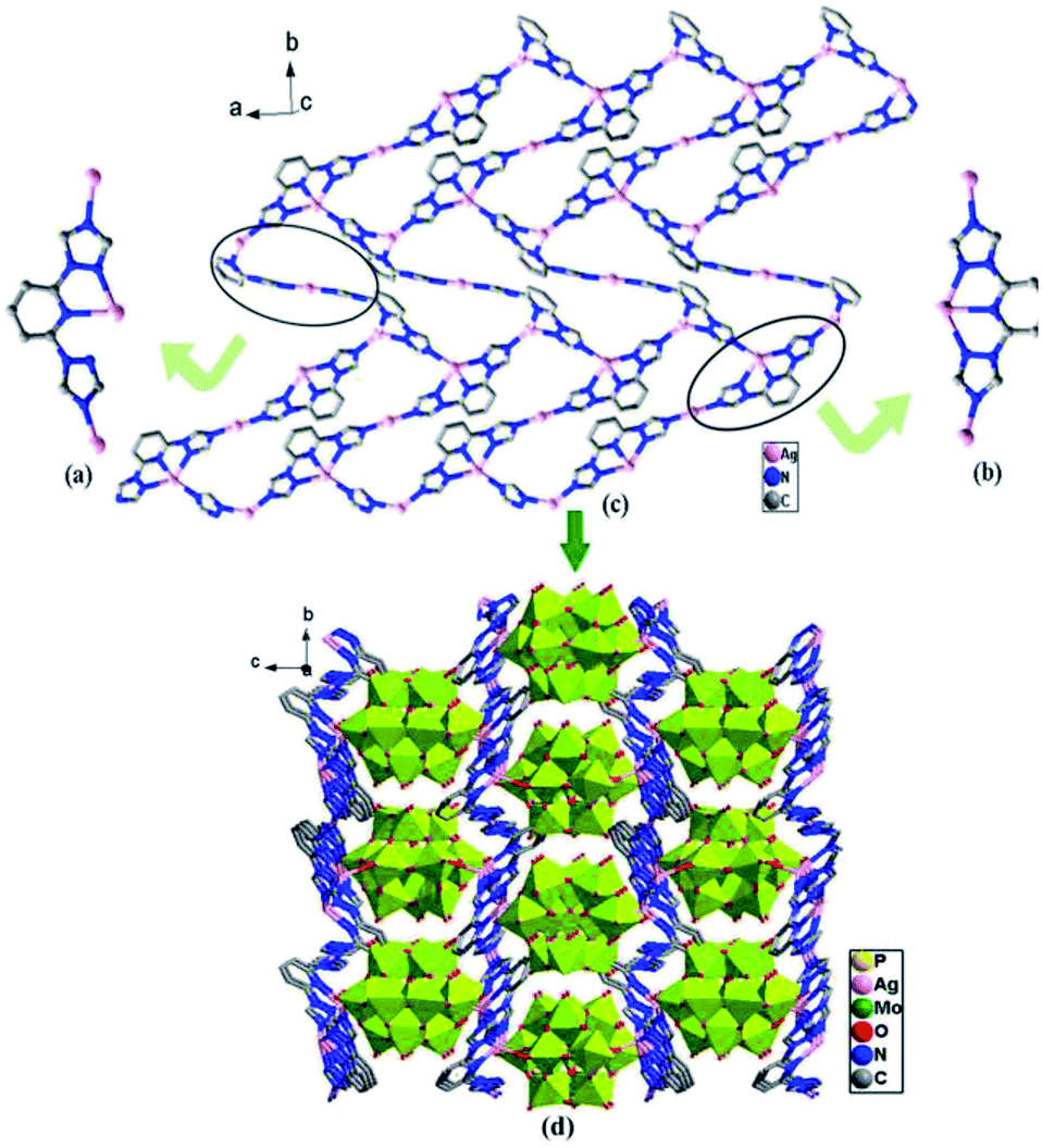
As shown in the Fig. 6a and b, different from those of compounds 1 and 2, two coordination modes of btp ligands (A: μ3-η1:η1:η1:η1; B: μ3-η1:η1:η1:η1:η1) are observed in compound 3, which link different Ag toms into 2D metal–organic layers (Fig. 6c). The 2D layers are further connected by Ag–O from [α-PMo12O40]3− anions to generate a 3D framework (Fig. 6d).
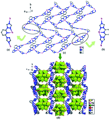 |
| | Fig. 6 (a) Coordination mode A of the btp ligand. (b) Coordination mode B of the btp ligand. (c) The 2D sheet. (d) The 3D network structure of the compound 3. (The hydrogen atoms and crystal water molecules are omitted for clarity.) | |
IR spectra, thermal stability and XRD
The IR spectra of 1–3 display the characteristic absorption bands of btp ligands. The characteristic peaks of 1609 cm−1, 1535 cm−1, 1468 cm−1 for 1, 1610 cm−1, 1521 cm−1, 1476 cm−1 for 2, 1609 cm−1, 1527 cm−1, 1460 cm−1 for 3 can be indicated the existence of btp ligands.34 The strong peaks at 783 cm−1, 887 cm−1 and 977 cm−1 for 1 are attributed to the ν (W–Oc), ν (W–Ob) and ν (W–Od); 814 cm−1, 900 cm−1, 985 cm−1 and 1075 cm−1 for 2 are assigned to the ν (W–Oc), ν (W–Ob), ν (W–Od) and ν (P–Oa); 789 cm−1, 877 cm−1, 953 cm−1 and 1065 cm−1 for 3 can be attributed to the ν (Mo–Oc), ν (Mo–Ob), ν (Mo–Od) and ν (P–Oa), respectively (Fig. S1, ESI†). All of the above demonstrate the presence of polyacid anions in the compounds 1–3.
The thermogravimetric analyses of the compounds 1–3 have been investigated under N2 atmosphere with the heating test range of 25–1000 °C by TGA. As shown in Fig. S2 (ESI†), the experimental results show that compounds 1–3 have high stability and exhibit similar two-step weight loss with the temperature for collapse of skeleton of about 391 °C for compound 1, 299 °C for compound 2 and 334 °C for compound 3.
In order to check the phase purities of the bulky solid sample for compounds 1–3, the X-ray powder diffractions of compounds 1–3 were carried out at room temperature with the angle in the range of 5–50°. As shown in Fig. S3 (ESI†), peaks of experimental patterns are in good agreement with as-synthesized diffraction peaks for compounds 1–3, which confirm the pure phase of the samples. The differences in intensity are because of the preferred orientation of crystalline powder samples.35
Electrochemical properties of compounds 1–3
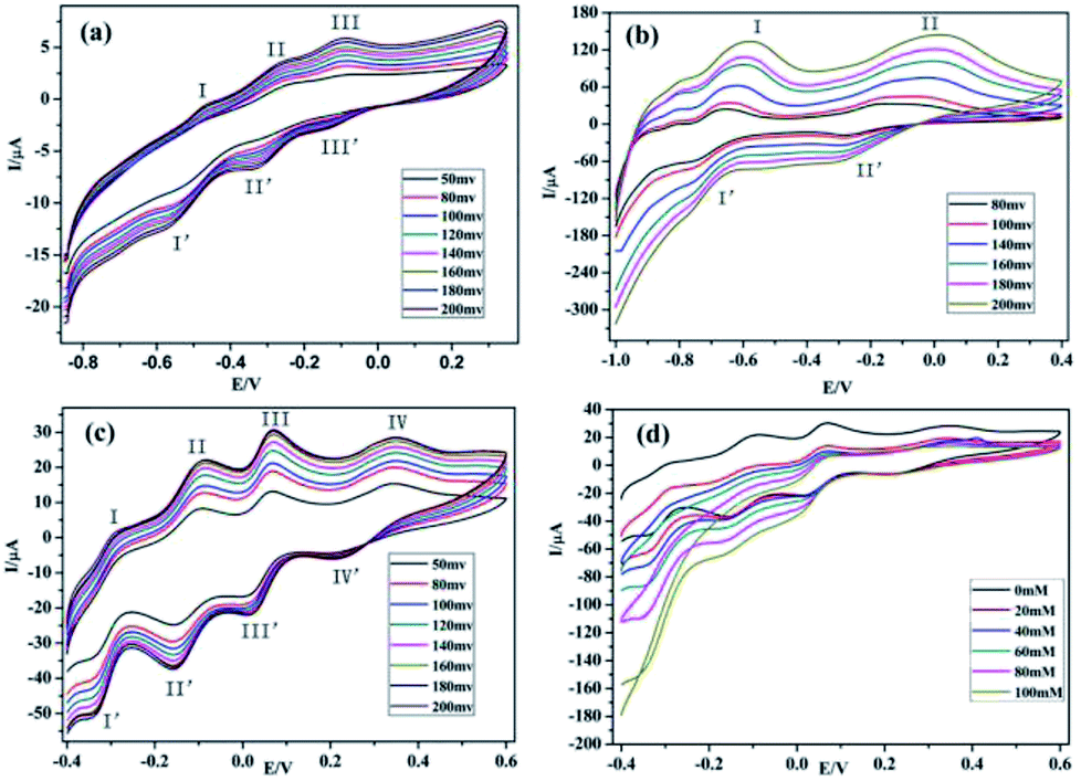
The glassy carbon electrodes (GCEs) become an optimal choice for studying the electrochemical properties of compounds 1–3, because of their good electrical conductivities and high chemical stabilities.36–38 In order to investigate the electrochemical behaviors of compounds 1–3, the three compounds have been used as modifiers to fabricate chemically modified electrodes (1–GCE, 2–GCE and 3–GCE). The cyclic voltammetric behaviors for 1–GCE, 2–GCE and 3–GCE in 0.5 mol L−1 Na2SO4 + 0.01 mol L−1 H2SO4 aqueous solution at different scan rates were recorded with the scan rate varying from 80 to 200 mV s−1 for 2–GCE, from 50 to 200 mV s−1 for 1–GCE and 3–GCE. In the potential range of −850 to 350 mV for 1–GCE, there are three pairs of reversible redox peaks (I–I′, II–II′ and III–III′), and the mean peak potentials E1/2 = (Epa + Epc)/2 of approximately −519.90, −294.88 and −114.79 mV can be clearly observed (Fig. 7a), which is attributed to two consecutive one-electron processes and one two-electron process of W atoms.39 For 2–GCE, two redox peaks (I–I′, II–II′) appear in the potential range of −100 to 400 mV (Fig. 7b), and the mean peak potentials E1/2 = (Epa + Epc)/2 are −675.63, −232.05 mV, respectively. Moreover the redox peaks I–I′ and III–III′ may be assigned to two consecutive two-electron redox processes of W centers.40 The 3–GCE has four reversible redox couples (I–I′, II–II′, III–III′ and IV–IV′) in the scan range of −0.4–0.6 V (Fig. 7c), which is mainly derived from the redox process of PMo12O403− anions, and the corresponding half-wave potential E1/2 = (Epa + Epc)/2 are located at −342.21, −252.56, 40.52 and 284.73 mV, respectively.41 At the same time, the peak potentials change gradually following the scan rates 80–200 mV s−1 for 2–GCE, 50–200 mV s−1 for 1–GCE and 3–GCE (Fig. S4, ESI†): the cathodic peak potentials shift toward the negative direction and the corresponding anodic peak potentials move to the positive direction. The peak currents are proportional to the square root of the scan rates up to 200 mV s−1, which indicates that the redox process of the 1–3–GCE is surface-controlled.42 In addition, electrocatalytic reduction for H2O2 of 3–GCE was also investigated. As shown in Fig. 7d, with the addition of H2O2, the four reduction peak currents increase markedly while the corresponding oxidation peak currents decrease, suggesting that the 3–GCE has good electrocatalytic activity for the reduction of H2O2.
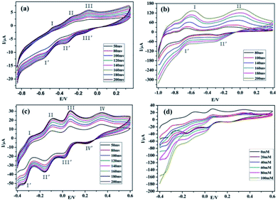 |
| | Fig. 7 (a)–(c) The cyclic voltammetric behaviors at different scan rates in 0.5 mol L−1 Na2SO4 + 0.01 mol L−1 H2SO4 solution for 1–GCE, 2–GCE and 3–GCE. (d) The electrocatalytic activity to reduce H2O2 in 0.5 mol L−1 Na2SO4 + 0.01 mol L−1 H2SO4 solution at the scan rate 200 mV s−1 for 3–GCE. | |
Photocatalytic properties of compounds 1–3
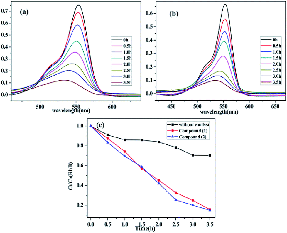
It is known that a wide range of POMs have photocatalytic activities during the degradation of organic dyes under UV irradiation. Therefore, the photocatalytic properties of POMs have a wide range of potential applications in purifying water quality.43 Herein, Rhodamine B (RhB) was used to investigate the photocatalytic performance of compounds 1–3 upon UV irradiation from a 300 W Hg lamp. Moreover, the photodegradation process of RhB without catalyst has also been studied under the same conditions (Fig. S5, ESI†). It can be clearly observed that the absorption peaks of RhB containing compounds 1–2 decrease obviously with increasing of reaction time (Fig. 8a and b). The calculations display that the degradation ratio of RhB was 84.44% for compound 1 and 85.14% for compound 2 after about the irradiation of 3.5 hours. Comparatively, the degradation ratio of RhB for compound 3 was 29.90%, which was lower than those of compounds 1 and 2 (Fig. S6, ESI†). The results indicate that compounds 1–2 have good photocatalytic activities for the degradation of RhB, which may be good candidates for photocatalysis to degrade the certain organic dyes (Fig. 8c).
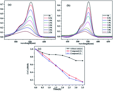 |
| | Fig. 8 (a) and (b) Absorption spectra of the RhB (10 mg L−1) solution during the decomposition reaction under UV light irradiation with the use of compound 1 and 2. (c) The comparison of the two compounds and no crystal decomposition rate of RhB in the same conditions. | |
Luminescent properties of compounds 1–3
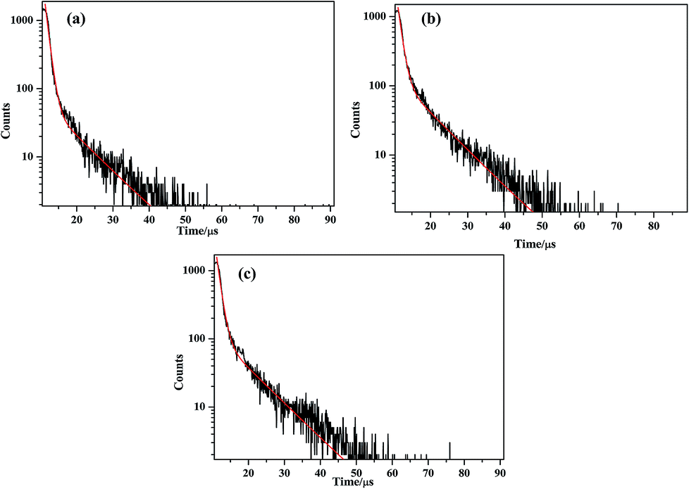
The solid-state photoluminescence of complexes 1–3 and the btp ligands were carried out at room temperature. As shown in the Fig. S7 (ESI†), the free btp ligands display two intense emissions at 442 and 466 nm upon excitation at 230 nm, while the main emission peaks are observed at about 430 and 454 nm for compound 1, 434 and 458 nm for compound 2, 435 and 459 nm for compound 3 upon the excitation of 230 nm, respectively. Compared by those of btp ligand, there is an obvious blue-shift of about 7–12 nm for three compounds. It can be inferred that those peaks originates from the π*–π transition of btp ligands.44,45 In order to further investigate the photoluminescent properties, luminescent decay curve was carried out by checking the emission at 454 nm (compound 1), 458 nm (compound 2) and 459 nm (compound 3), which can be well fitted into a double-exponential decay function as I = A1![[thin space (1/6-em)]](https://www.rsc.org/images/entities/char_2009.gif) exp(−t/τ) + A2exp(−t/τ), affording the lifetime: τ1 = 938.66 ns (78.17%) and τ2 = 8271.71 ns (21.83%) for compound 1, τ1 = 1000.00 ns (58.00%) and τ2 = 8043.97 ns (42.00%) for compound 2, τ1 = 1037.39 ns (64.92%) and τ2 = 8415.63 ns (35.08%) for compound 3, the pre-exponential factor: A1 = 1853.76, A2 = 58.74 (compound 1) (Fig. 9a); A1 = 1357.10, A2 = 122.15 (compound 2) (Fig. 9b); A1 = 1610.91, A2 = 107.32 (compound 3) (Fig. 9c). Therefore, the average lifetime of 2.5393 μs for compound 1, 3.9582 μs for compound 2, 3.6260 μs for compound 3 based on the formula τ = (A1τ12 + A2τ22)/(A1τ1 + A2τ2).46
exp(−t/τ) + A2exp(−t/τ), affording the lifetime: τ1 = 938.66 ns (78.17%) and τ2 = 8271.71 ns (21.83%) for compound 1, τ1 = 1000.00 ns (58.00%) and τ2 = 8043.97 ns (42.00%) for compound 2, τ1 = 1037.39 ns (64.92%) and τ2 = 8415.63 ns (35.08%) for compound 3, the pre-exponential factor: A1 = 1853.76, A2 = 58.74 (compound 1) (Fig. 9a); A1 = 1357.10, A2 = 122.15 (compound 2) (Fig. 9b); A1 = 1610.91, A2 = 107.32 (compound 3) (Fig. 9c). Therefore, the average lifetime of 2.5393 μs for compound 1, 3.9582 μs for compound 2, 3.6260 μs for compound 3 based on the formula τ = (A1τ12 + A2τ22)/(A1τ1 + A2τ2).46
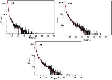 |
| | Fig. 9 (a)–(c) The luminescence decay curves taken by monitoring the emission at 454 nm for compounds 1–3. | |
Magnetic property of compound 1
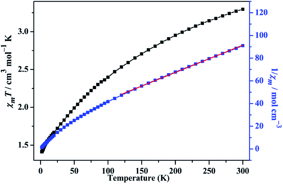
The temperature-dependent magnetic susceptibility data of compound 1 is measured for the crystal samples in the 2–300 K temperature range under an applied field of 1000 Oe. The χmT and χm−1 versus T are shown in the Fig. 10. The χmT value is 3.296 cm3 mol−1 K at 300 K, which is smaller than the expected (3.75 cm3 mol−1 K) for one isolated Co(II) ion (g = 2.5, S = 3/2).47 As the temperature decreasing, the χmT value continuously reduces to 1.414 cm3 mol−1 K at 2 K, which is an indicative to the presence of antiferromagnetic exchange interactions between the Co(II) magnetic centers. The temperature dependence of the reciprocal susceptibility χm−1 of compound 1 obeys the Curie–Weiss law in the temperature range of 120–300 K, giving C = 4.160 cm3 mol−1 K, θ = −80.374 K, which further confirm the antiferromagnetic interaction between Co(II) ions. To further investigate the magnetic interactions, the variation of magnetizations with field strengths was also tested at 2 K (Fig. S8, ESI†). The M value is 2.072 Nβ when the field reaches 7 T, lower than the expected value of 3.75 Nβ, which is also characteristic of antiferromagnetic interaction.
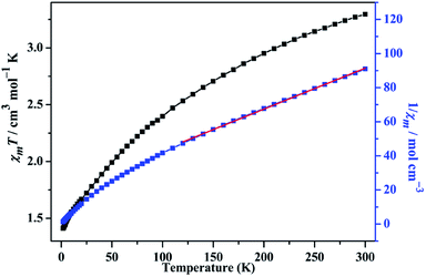 |
| | Fig. 10 The χmT vs. T and χm−1 vs. T plots of 1 in the range of 2–300 K at 1000 Oe, the red solid line represents the best fit. | |
Conclusion
In conclusion, three novel inorganic–organic hybrid materials [Co2(btp)4(W10O32)(H2O)2]n (1), [Cd3(btp)(PW12O40)2(H2O)6·6H2O]n (2), [Ag3(btp)2(PMo12O40)·1.5H2O]n (3) (btp = 2,6-bis(1,2,4-triazol-1-yl)pyridine) have successfully been synthesized through hydrothermal methods. Three compounds exhibit 3D frameworks of various structures due to different coordination modes of the ligands, different coordination environment of the metal ions and different polyoxoanions. Compound 1 is a rare 3D polycatenation framework, interpenetrated by a 2D 4-connected sql layer with {44·62} topology and a 3D 6-connected framework with rob network structure with {48·66·8} topology; the unusual meso-helices 3D network of compound 2 comprises of the crossing left- and right-helical chains following different axial directions while the 3D framework is formed by 2D metal–organic layer connected by Ag–O bond from [α-PMo12O40]3− anions in compound 3. In addition, the magnetism of compound 1, the luminescent, photocatalytic and electrochemical properties of compounds 1–3 have been investigated. The results show that three compounds display luminescent behaviors at solid state. In addition, compound 1 displays antiferromagnetic behavior, compounds 1–2 show efficient catalytic activities for the degradation of Rhodamine B (RhB), and compound 3 exhibits significant electrochemical activity for the reduction of H2O2.
Conflicts of interest
There are no conflicts to declare.
Acknowledgements
The research is financially supported by the National Natural Science Foundation of China (U1504209, 21403053), Young Backbone Teacher Project of Henan Colleges and Universities (2016GGJS-023) and Foundation of Henan University (0000A40478).
Notes and references
- W. Salomon, E. Rivière, X. López, N. Suaud, P. Mialane, M. Haouas, A. Saad, J. Marrot and A. Dolbecq, Dalton Trans., 2018, 47, 10636–10645 RSC
 .
. - M. S. S. Balula, I. C. M. S. Santos, J. A. F. Gamelas, A. M. V. Cavaleiro, N. Binsted and W. Schlindwein, Eur. J. Inorg. Chem., 2007, 7, 1027–1038 CrossRef .
- C. G. Liu, S. Liu and T. Zheng, Inorg. Chem., 2015, 54, 7929–7935 CrossRef CAS .
- M. Carraro and S. Gross, Materials, 2014, 7, 3956–3989 CrossRef CAS PubMed .
- X. F. Li, X. Wang, Y. Y. Wu, X. W. Zhao, H. Y. Li and Y. M. Li, J. Solid State Chem., 2019, 269, 118–124 CrossRef CAS .
- X. F. Li, Y. Y. Wu, H. J. Lun, H. Y. Li, J. H. Yang and Y. M. Li, Synth. Met., 2017, 232, 103–110 CrossRef CAS .
- X. J. Yang, M. Sun, H. Y. Zang, Y. Y. Ma, X. J. Feng, H. Q. Tan, Y. H. Wang and Y. G. Li, Chem.–Asian J., 2016, 11, 858–867 CrossRef CAS .
- S. B. Li, L. Zhang, K. P. O'Halloran, H. Y. Ma and H. J. Pang, Dalton Trans., 2015, 44, 2062–2065 RSC .
- X. L. Hao, Y. Y. Ma, Y. H. Wang, L. Y. Xu, F. C. Liu, M. M. Zhang and Y. G. Li, Chem.–Asian J., 2014, 9, 819–829 CrossRef CAS .
- W. L. Zhou, Y. P. Zheng and J. Peng, J. Solid State Chem., 2018, 258, 786–791 CrossRef CAS .
- J. Q. Sha, P. P. Zhu, X. Y. Yang, N. Sheng, J. S. Li, L. J. Sun and H. Yan, CrystEngComm, 2016, 18, 7049–7055 RSC .
- B. W. Cong, Z. H. Su, Z. F. Zhao, B. Y. Yu, W. Q. Zhao, L. Xia, X. J. Ma and B. B. Zhou, CrystEngComm, 2017, 19, 2739–2749 RSC .
- Z. Z. He, D. Ma, B. R. Cao, X. Q. Li and Y. Lu, Inorg. Chim. Acta, 2018, 471, 316–325 CrossRef CAS .
- X. L. Wang, R. Zhang, X. Wang, H. Y. Lin, G. C. Liu and H. X. Zhang, Dalton Trans., 2017, 46, 1965–1974 RSC .
- C. J. Zhang, H. J. Pang, Q. Tang, H. Y. Wang and Y. G. Chen, Dalton Trans., 2010, 39, 7993–7999 RSC .
- A. X. Tian, X. J. Liu, J. Ying, D. X. Zhu, X. L. Wang and J. Peng, CrystEngComm, 2011, 13, 6680–6687 RSC .
- H. Zhang, K. Yu, S. Gao, C. M. Wang, C. X. Wang, H. Y. Wang and B. B. Zhou, CrystEngComm, 2014, 16, 8449–8456 RSC .
- X. L. Wang, J. J. Cao, G. C. Liu, A. X. Tian, J. Luan, H. Y. Lin, J. W. Zhang and N. Li, CrystEngComm, 2014, 16, 5732–5740 RSC .
- K. T. Youm, H. K. Woo, J. Ko and M. J. Jun, CrystEngComm, 2007, 9, 30–34 RSC .
- J. R. Miecznikowski, J. P. Jasinski, M. A. Lynn, S. S. Jain, E. E. Butrick, A. E. R. Drozdoski, K. A. Archer and J. T. Panarra, Inorg. Chim. Acta, 2013, 394, 310–321 CrossRef CAS .
- G. M. Seldrick, SHELXS-97, Program for X-ray Crystal Structure Solution, University of Göttingen, Göttingen, Germany, 1997 Search PubMed .
- G. M. Sheldrick, Acta Crystallogr., Sect. C: Struct. Chem., 2015, 71, 3–8 Search PubMed .
- G. M. Sheldrick, SHELXL-97, Program for X-ray Crystal Structure Refinement, University of Göttingen, Göttingen, Germany, 1997 Search PubMed .
- G. M. Sheldrick, Acta Crystallogr., Sect. A: Found. Crystallogr., 2008, 64, 112–122 CrossRef CAS .
- Y. B. Liu, W. J. Duan, X. B. Cui and J. Q. Xu, Chem. Res. Chin. Univ., 2015, 31, 4–8 CrossRef CAS .
- R. F. D. Luis, M. K. Urtiaga, J. L. Mesa, A. T. Aguayo, T. Rojo and M. I. Arriortuaa, CrystEngComm, 2010, 12, 1880–1886 RSC .
- Y. Q. Lan, S. L. Li, Z. M. Su, K. Z. Shao, J. F. Ma, X. L. Wang and E. B. Wang, Chem. Commun., 2008, 1, 58–60 RSC .
- X. F. Kuang, X. Y. Wu, J. Zhang and C. Z. Lu, Chem. Commun., 2011, 7, 4150–4152 RSC .
- H. Wu, J. Yang, Y. Y. Liu and J. F. Ma, Cryst. Growth Des., 2012, 12, 2272–2276 CrossRef CAS .
- L. Carlucci, G. Ciani and D. M. Proserpio, Coord. Chem. Rev., 2003, 246, 247–289 CrossRef CAS .
- L. Hou, J. P. Zhang and X. M. Chen, Cryst. Growth Des., 2009, 9, 2415–2419 CrossRef CAS .
- J. Q. Chen, Y. P. Cai, H. C. Fang, Z. Y. Zhou, X. L. Zhan, G. Zhao and Z. Zhang, Cryst. Growth Des., 2009, 9, 1605–1613 CrossRef CAS .
- Y. Huang, B. Yan and M. Shao, J. Solid State Chem., 2009, 182, 657–668 CrossRef CAS .
- Y. M. Li, C. Y. Xiao, X. D. Zhang, Y. Q. Xu, H. J. Luna and J. Y. Niu, CrystEngComm, 2013, 15, 7756–7762 RSC .
- H. J. Lun, X. F. Li, X. Wang, H. Y. Li, Y. M. Li and Y. Bai, J. Mol. Struct., 2017, 1127, 662–667 CrossRef CAS .
- Y. H. Zhang, W. Lei, Q. J. Wu, X. F. Xia and Q. L. Hao, Microchim. Acta, 2017, 184, 3103–3111 CrossRef CAS .
- M. Musameh, M. R. Notivoli, M. Hickey, C. P. Huynh, S. C. Hawkins, J. M. Yousef and I. L. Kyratzis, Electrochim. Acta, 2013, 101, 209–215 CrossRef CAS .
- H. J. Lun, S. S. Cui, H. J. Li, Q. Ping, H. H. Song, Y. M. Li, Y. Ru, Y. L. Bai and S. C. Xiang, CrystEngComm, 2015, 17, 7029–7033 RSC .
- H. J. Pang, J. Peng, J. Q. Sha, A. X. Tian, P. P. Zhang, Y. Chen and M. Zhu, J. Mol. Struct., 2009, 922, 88–92 CrossRef CAS .
- X. Wang, J. Peng, K. Alimaje, Z. Y. Zhang and Z. Y. Shi, Inorg. Chem. Commun., 2013, 36, 141–145 CrossRef CAS .
- X. L. Wang, Y. F. Bi, B. K. Chen, H. Y. Lin and G. C. Liu, Inorg. Chem., 2008, 47, 2442–2448 CrossRef CAS .
- Q. H. Guo, J. S. Huang, P. Q. Chen, Y. Liu, H. Q. Hou and T. Y. You, Sens. Actuators, B, 2012, 163, 179–185 CrossRef CAS .
- S. Roy, V. Vemuri, S. Maiti, K. S. Manoj, U. Subbarao and S. C. Peter, Inorg. Chem., 2018, 57, 12078–12092 CrossRef CAS PubMed .
- Q. Y. Liu, W. F. Wang, Y. L. Wang, Z. M. Shan, M. S. Wang and J. K. Tang, Inorg. Chem., 2012, 51, 2381–2392 CrossRef CAS PubMed .
- Y. M. Li, X. F. Li, Y. Y. Wu, D. L. Collins-Wildman, S. M. Hu, Y. Liu, H. Y. Li, X. W. Zhao, L. Y. Jin and D. B. Dang, Cryst. Growth Des., 2018, 18, 7541–7547 CrossRef CAS .
- T. Fujii, K. Kodaira, O. Kawauchi and N. Tanaka, J. Phys. Chem. B, 1997, 101, 10631–10637 CrossRef CAS .
- Y. M. Li, H. J. Lun, C. Y. Xiao, Y. Q. Xu, L. Wu, J. H. Yang, J. Y. Niu and S. C. Xiang, Chem. Commun., 2014, 50, 8558–8560 RSC .
Footnote |
| † Electronic supplementary information (ESI) available: IR spectra, PXRD patterns, TG curves; additional electrochemical, luminescence, photocatalytic and magnetic characterizations; crystallographic data, bond distances and angles. CCDC 1895048–1895050. For ESI and crystallographic data in CIF or other electronic format see DOI: 10.1039/c9ra01451a |
|
| This journal is © The Royal Society of Chemistry 2019 |
Click here to see how this site uses Cookies. View our privacy policy here. 
 Open Access Article
 This Open Access Article is licensed under a Creative Commons Attribution-Non Commercial 3.0 Unported Licence
 *,
Dongbin Dang
*,
Dongbin Dang