DOI:
10.1039/C9RA01379B
(Paper)
RSC Adv., 2019,
9, 15457-15465
Preparation of graphene oxide/poly(vinyl alcohol) composite membrane and pervaporation performance for ethanol dehydration
Received
23rd February 2019
, Accepted 5th May 2019
First published on 17th May 2019
Abstract
Although poly(vinyl alcohol) (PVA) membranes are widely used in solvent dehydration by pervaporation, the separation factor is rather limited. Considering this, novel PVA mixed matrix membranes with graphene oxide (GO) nanosheets were prepared. poly(acrylonitrile) ultrafiltration (PAN) membrane was used as support layer. The PVA/GO composite membranes were characterized by Fourier transform infrared spectroscopy, X-ray diffractometry, scanning electron microscopy, thermogravimetric analysis and water contact angle. We also explored the pervaporation performance of the membrane for ethanol dehydration. GO slightly improves the thermal stability and crystallinity of the composite membranes. In addition, the hydrophilicity of the composite membranes is weakened after GO addition, but the crosslinking degree is increased, resulting a significant increase in the separation factor and a certain decrease in the total flux. With the amount of GO addition increases, the total flux of the PVA/GO composite membrane decreases, while the separation factor increases first and then decreases, and the preferred amount of GO addition is 2.0 wt%. Especially, the separation factor of the composite membranes with 2.0 wt% GO addition could reach 3 059, which is 16 times higher than PVA membranes, with the corresponding permeability flux is 145 g m−2 h−1.
1. Introduction
As a renewable energy source, fuel ethanol is the development focus of alternative fuels energy in the world, and it has good economic and social benefits and hopes to partially replace gasoline and diesel.1,2 Pervaporation technology (PV)3 could separate ethanol–water mixture with high efficiency and low energy consumption,4 providing an opportunity for the application of anhydrous fuel ethanol. At present, pervaporation technology has been industrialized in the field of organic solvent dehydration. In 1982, GFT of Germany took the lead in building the world's first pervaporation unit for ethanol dehydration via cross-linked poly(vinyl alcohol) (PVA) membranes. PVA5,6 is non-toxic, inexpensive and biodegradable water-soluble polymers with hydroxyl groups in molecular chain and strict linear structures. It has high hydrophilicity and good membrane forming property, which is used for organic solvents dehydration and exhibits superior separation performance. However, PVA is poor in water resistance and tends to swell excessively in aqueous solution, which makes it weak in mechanical strength and thermal stability, resulting in sharp drops in separation performance. Table 1 contains some key data on the PVA membrane for organic solvents dehydration by pervaporation. As can be seen from Table 1, for the ethanol–water system, the separation factor of PVA membranes with different cross-linking methods was rather limited. To solve the problem, various modification techniques such as blending, grafting, and crosslinking are employed. Among them, doping inorganic nanomaterials have become an important research direction, polymer nanocomposites membranes were prepared by PVA with nano-SiO2,17,18 NaA zeolite,19 nano-TiO2,20 carbon nitride,21,22 Ag,23,24 and other inorganic nanomaterials. Arif et al.17 synthesized PVA/silica membranes by sol–gel derived route for application in pervaporation of isopropanol–water mixture. The chemically cross-linked composite membrane prepared showed improved performance concerning flux and selectivity when compared to the pristine PVA membrane. The addition of silica changes semi-crystalline PVA to an amorphous polymer which favoured diffusion of the water molecule to permeate through membrane hence flux increases. In the work of Wang et al.21 hybrid membranes with excellent water/ethanol separation performance and superior water channels were fabricated by incorporating g-C3N4 nanosheets into a PVA matrix. Due to the strong interfacial interactions between g-C3N4 and PVA, the hybrid nanocomposite membranes showed both high swelling resistance and mechanical stability. The total flux and separation factor of the new membrane can reach to 6332 g m−2 h−1, and 30.7 for 90 wt% ethanol, respectively. Compared with the cross-linked pure PVA membrane (2337 g m−2 h−1 and 11.2), the composite membrane could break the “trade-off effect” effectively. In the study of Premakshi et al.25 the silver nanoparticles were in situ prepared before crosslinking PVA matrix by reducing of silver ions using sodium borohydride. The membranes were under go pervaporation for separation of water from isopropanol at different temperatures. The results indicated that hydrophilicity and amorphous nature of the membranes were increased with increasing silver nanoparticles in PVA matrix, and permeation flux and selectivity were increased simultaneously. Among the membranes studied, the membrane containing 2.5 wt% of Ag-Nps demonstrated the highest separation selectivity of 634 with a flux of 71.6 g m−2 h−1.
Table 1 Dehydration of organic solvents using PVA membranes
| Solution–water mixture (mass ratio) |
Membrane |
Cross-linker |
Flux (g m−2 h−1) |
Separation factor |
Temperature (°C) |
Ref. |
Isopropanol/water (90![[thin space (1/6-em)]](https://www.rsc.org/images/entities/char_2009.gif) :10) :10) |
PVA |
Glutaraldehyde |
40 |
21 |
30 |
7 |
| Isopropanol/water (90:10) |
PVA |
UFS solution |
95 |
77 |
30 |
8 |
| Isopropanol/water (80:20) |
PVA |
Thermally cross-linked |
140 |
40 |
50 |
9 |
| Acetic acid/water (90:10) |
PVA |
Glutaraldehyde |
100 |
9 |
30 |
10 |
| Acetic acid/water (90:10) |
PVA |
— |
37.1 |
11.61 |
45 |
11 |
| Acetic acid/water (90:10) |
PVA |
Malic acid |
48 |
670 |
40 |
12 |
| Tetrahydrofuran/water (95:5) |
PVA |
UFS solution |
210 |
210 |
30 |
8 |
| Ethanol/water (azeotrope) |
PVA |
— |
120 |
10 |
60 |
13 |
| Ethanol/water (90:10) |
PVA |
Dimethylolurea |
120 |
115 |
60 |
14 |
| Ethanol/water (90:10) |
PVA |
Glutaraldehyde |
95 |
77.3 |
30 |
15 |
| Ethanol/water (80:20) |
PVA |
Thermally cross-linked |
183 |
15.5 |
50 |
9 |
| Ethanol/water (95:5) |
PVA (GFT 1510/2510) |
Malic acid |
600 |
258 |
60 |
16 |
Graphene26 is a single-layer crystal with honeycomb lattice structure. As a new type of nanomaterial with the thinnest, strongest and thermal conductivity, the research trend of its application value is still in the ascendant. The only one-atom thick and nearly frictionless surface enables graphene to form membranes that minimize transport resistance and maximize permeate flux. Bunch et al.27 attributed the ultra-fast transport of water to a low-friction flow of a monolayer of water through 2D capillaries formed by closely spaced graphene sheets and diffusion of other molecules is blocked by reversible narrowing of the capillaries in low humidity and/or by their clogging with water. The graphene-based membranes28 could be used as functional membranes for constructing high separation performance, while graphene has strong hydrophobicity and low reactivity and it has certain limitations as pervaporation dehydration membranes. Graphene oxide (GO) is a derivative of graphene,28,29 which has a similar two-dimensional structure to graphene. In addition to the six-membered ring skeleton of carbon atoms, it also contains polar oxygen-containing functional groups such as hydroxyl groups, epoxy groups, carboxyl groups, and carbonyl groups. The pioneering work of Geim et al.30 found that submicrometer-thick laminates formed from GO can be completely impermeable to liquids, vapors and gases, yet allow unimpeded permeation of water. Besides, molecular transport within GO-based membranes is particularly benefited by the oxygen atoms bonded to the carbon atoms in the oxidized regions of graphene play the role of spacers that keep graphene planes about 0.7 to 1.0 nm apart in GO laminates, and the pristine regions create almost frictionless 2D nanochannels for transporting water molecules across GO laminates. GO exhibits outstanding hydrophilicity and facilitates to further modification attributed to the complex and active structure, thereby preparing nanocomposite membranes with excellent properties. Tang et al.31 assembled free-standing GO membranes by pressurized ultrafiltration method, and studied the pervaporation performance of ethanol dehydration. Experimental results suggest that the interlaminar spacing is determined by both packing density of GO nanosheets and water content in the feed solution. By tuning the ultrafiltration pressure, a high separation performance with water permeability of 13800 barrer (1 barrer = 3.348 × 10⁻¹⁹ kmol m m−2 s−1 Pa−1) and water/ethanol selectivity of 227 is achieved for dehydration of an 85 wt% ethanol aqueous solution at 24 °C. The high stability and hydrophilic layered packing structure of the GO sheets and the appropriate layer spacing allow it to preferentially transport water.
In this paper, PVA/GO nanocomposite membranes32–34 with different GO content were prepared and analysed by attenuated total reflectance-Fourier transform infrared spectroscopy (ATR-FTIR), scanning electron microscopy (SEM), X-ray diffractometry (XRD), and thermogravimetric analysis (TGA), water contact angle (WCA) and degree of swelling. The pervaporation performance of membranes for ethanol dehydration was also tested.
2. Experimental
2.1 Material
Poly(vinyl alcohol) (PVA) with Mw ∼ 100000 was obtained from Beijing Organic Chemical Co., Ltd. (Beijing, China). Flake graphite powder (325 mesh) was purchased from Nanjing Xian Feng Nano Material Technology Co., Ltd. (China). Sulfuric acid (H2SO4, >98%), sodium nitrate (NaNO3, AR) and potassium permanganate (KMnO4, >99%) were supplied by Modern Oriental (Beijing) Technology Development CD., LTD. (Beijing, China). Hydrochloric acid (HCl, AR) and hydrogen peroxide (H2O2, 30 vol%) were from Shanghai Jinlu Chemical Co., Ltd. (Shanghai, China). Glutaraldehyde acts (GA, 50%) was purchased from Tianjin Guangfu Fine Chemical Research Institute (China). Acetic acid (HAc, AR) and ethanol (AR) were supplied by Modern Oriental Technology Development Co., Ltd. (Beijing, China).
2.2 Synthesis of GO
Graphene oxide was synthesized following the modified Hummers' method.35 The steps were as follows: 2.5 g of NaNO3 and 115 ml of 98 wt% H2SO4 were mixed in an ice bath for 10 min. 5 g of graphite powder was added and stirred for 1 h. Then 15 g of KMnO4 was slowly added in batches to keep the temperature under 20 °C. After 1 h, stirring was continued for 2 hours at 35 °C. The temperature of the mixture was adjusted to 98 °C for 30 min while 230 ml of deionized water was added continuously. Then stop the reaction with a large amount of deionized water. Added 30% H2O2 to the solution, the reaction product was centrifuged and washed deionized water and 5% HCl solution repeatedly to remove the metal ions from the product. Then sonicated for 1 h and freeze-drying to obtain dark brown graphene oxide (GO) powder finally.36
2.3 Fabrication of composite PVA/GO membranes
The synthesized GO was ultrasonically dispersed in deionized water to prepare GO suspension. PVA powder was dissolved in 2.0 wt% acetic acid solution, continuously stirred for 2 h at 90 °C to obtain PVA solutions.
Different amount of graphene oxide (GO) suspension was added in PVA solutions. The solutions were sonication for 30 min to uniformly disperse GO in the PVA solution. Then, the mixture were stirred in a water bath at 90 °C for 1 h, and ultrasonic for 30 min. 2 wt% glutaraldehyde acts (GA) as a crosslinking agent was added, and stirred for 1 h. Finally, the obtained casting solution was degassed at room temperature. Cut out a certain size of PAN ultrafiltration membrane and tape it to clean and flat glass plates. Then poured PVA/GO casting solution onto the based membranes to cast and then dried for 12–14 h at room temperature. Finally react at 60 °C for 1 h to prepare PVA/GO composite membranes with 0.0 wt%, 1.0 wt%, 2.0 wt%, 3.0 wt%, 4.0 wt% GO, recorded as GOP-0.0, GOP-0.5, GOP-1.0, GOP-2.0, GOP-3.0, GOP-4.0.
2.4 Pervaporation performance of composite membranes
The pervaporation dehydration performance of the PVA/GO composite membranes was assessed on a self-designed stainless steel apparatus in our lab, and flow diagram was illustrated in Fig. 1. The PVA/GO composite membrane was cut and put into the membrane cell (the effective area of the membrane was 2.2 × 10⁻³ m2). The feed tank was heated by electric heating coil and material liquid was pressurized by a magnetic pump from the feed tank (about 2.5 × 10⁻³ m3) to the upper side of the membrane cell under set temperature. The down-stream pressure was maintained at 200 Pa. The permeate component was condensed by liquid nitrogen and collected in the cold trap, and the mass of the permeate component was accurately weighed. Contents of upstream feed solution and downstream permeate, which consisted of ethanol and water, were analysed with the aid of chromatography (Shimadzu, GC-14C, Japan).
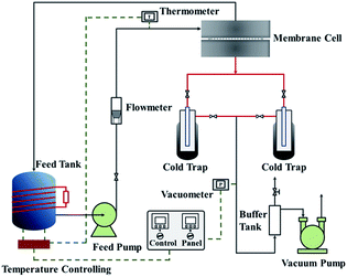 |
| | Fig. 1 Flow chart of pervaporation evaluation apparatus. | |
Pervaporation performances indicators mainly include permeate flux J and separation factor α, which are defined as follows:
| |
 | (1) |
| |
 | (2) |
where
m is the mass of permeating mixture (g),
A is the membrane effective surface area (m
2),
t is the collecting time (h),
J is the total flux (g m
−2 h
−1),
YA and
YB are the concentrations (wt%) of ethanol and water in the permeate respectively.
XA and
XB are the concentrations (wt%) of ethanol and water in the feed solution respectively, and subscripts A and B represent ethanol and water respectively.
2.5 Membrane characterization
The infrared spectra of composite membranes were analysed with Fourier transform infrared spectroscopy (ATR-FTIR, BRUKER TENSOR 27). All samples were collected from a wave number of 700–4000 cm−1 at a resolution of 2.0 cm−1. The diffraction patterns and the orientation of crystalline phases of composite membranes were tested by Bruker D8 ADVANCE Diffractometer (Germany) with λ = 1.54 Å in the range 5° ≤ 2θ ≤ 90°. The exfoliation of GO powder was also investigated via XRD. Surface and cross section images of all types of membranes were observed by scanning electron microscopy (SEM, JSM7401F, Japan). The membranes were first cryogenically fractured in liquid nitrogen bath to expose their cross-sections. Prior to the measurement, all samples were adhered to the metal sample stage with a conductive paste and gold (GATAN MODEL-862; JEOL-JHC-1100) was applied under vacuum. Water contact angle (WCA, Model PV-DP) was experimented to show the hydrophobicity and hydrophilicity of composite membrane. In a nitrogen atmosphere, thermogravimetric analysis (TGA, 1600 HT, Mettler-Toledo, Switzerland) with a temperature range of 30–700 °C and a heating rate of 10°C min−1 was used to test the heat resistance and thermal stability of the membrane varies with increasing temperature. Swelling tests on the membranes of the GOP membrane were performed gravimetrically.
3. Results and discussion
3.1 Characterization of samples
The Fourier transform infrared spectroscopy (FTIR) of the composite GOP membranes was analysed, as shown in Fig. 2. There is a broad absorption peak at 3267 cm−1, which is generated by the stretching vibration of the –OH groups. It could be observed that the peak intensity of the PVA/GO composite membranes here is weaker than that of the pristine PVA membranes (GOP-0.0), and the peak intensity become weaker with increasing GO in PVA matrix, which possible owing to the crosslinking reaction between PVA and GA increases as increasing GO, so the number of –OH groups decreases. The C![[double bond, length as m-dash]](https://www.rsc.org/images/entities/char_e001.gif) O stretching vibration in the carboxyl group is observed at 1709 cm−1, and the absorption peak at 1234 cm−1 is generated by the C–O groups stretching vibration. The absorption peak observed at 1090 cm−1 is the asymmetric stretching vibration of C–O–C groups, indicating that the aldehyde groups of GA cross-linked with –OH groups of GO and PVA to produce C–O–C bonds. In addition, the peak intensity of the PVA/GO composite membranes is significantly weaker than the PVA membrane at 1090 cm−1, further demonstrating that GO could enhance the crosslinking degree of the composite membranes. The cross-linking density of the composite membrane can be analysed by semi-quantitative analysis of the peak height ratio of 3267 cm−1 (O–H) and 2940 cm−1 (C–H) in the infrared spectrum.37 It can be seen from Table 2 that with the amount of GO addition increases, the peak height ratio of the composite membrane decreases, indicating that cross linking density of the composite membrane increases with GO content increases. The ATR-FTIR analysis reasonably explains the strong interaction between PVA and GO.
O stretching vibration in the carboxyl group is observed at 1709 cm−1, and the absorption peak at 1234 cm−1 is generated by the C–O groups stretching vibration. The absorption peak observed at 1090 cm−1 is the asymmetric stretching vibration of C–O–C groups, indicating that the aldehyde groups of GA cross-linked with –OH groups of GO and PVA to produce C–O–C bonds. In addition, the peak intensity of the PVA/GO composite membranes is significantly weaker than the PVA membrane at 1090 cm−1, further demonstrating that GO could enhance the crosslinking degree of the composite membranes. The cross-linking density of the composite membrane can be analysed by semi-quantitative analysis of the peak height ratio of 3267 cm−1 (O–H) and 2940 cm−1 (C–H) in the infrared spectrum.37 It can be seen from Table 2 that with the amount of GO addition increases, the peak height ratio of the composite membrane decreases, indicating that cross linking density of the composite membrane increases with GO content increases. The ATR-FTIR analysis reasonably explains the strong interaction between PVA and GO.
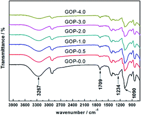 |
| | Fig. 2 ATR-FTIR spectra of GOP composite membranes. | |
Table 2 The peak height ratio of 3267 cm−1 and 2940 cm−1 in the infrared spectrum of different membranes
| Membrane |
GOP-0.0 |
GOP-0.5 |
GOP-1.0 |
GOP-2.0 |
GOP-3.0 |
GOP-4.0 |
| h (3267 cm−1)/h (2940 cm−1) |
1.384 |
1.360 |
1.334 |
1.312 |
1.282 |
1.255 |
PVA is a polymer with high crystallinity, and loading GO into pristine PVA could affect its crystallinity.38 XRD patterns of the graphite and GO powder is presented in Fig. 3, and the XRD spectrum of crosslinked composite GOP membranes is shown in Fig. 4. The d-spacing of the sheets structure was estimated by the Bragg formula.
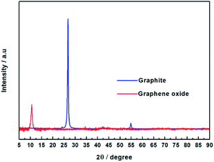 |
| | Fig. 3 XRD patterns of graphite and GO powder. | |
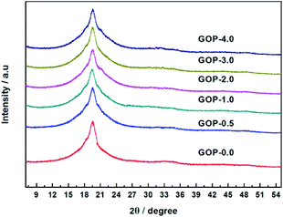 |
| | Fig. 4 XRD patterns of GOP membranes. | |
From Fig. 3, it was found that graphite showed a strong diffraction peak at 2θ = 26.67° (d-spacing = 3.34 Å), which indicated a typical two dimensional layer structure of sp2 hybridization.39 No diffraction peak appeared at 2θ = 26.67° in the graphene oxide XRD pattern, it shows that GO was successfully synthesized and did not contain the graphite. In contrast, GO exhibits a sharp diffraction peak at 2θ = 10.57°, the layer spacing of GO can be calculated to be 8.36 Å, which is increased compared to the layer spacing of graphene (3.34 Å). This is due to graphene have a large amount of oxygen-containing functional groups after oxidation, which increases the GO d-spacing. According to Fig. 4, the pristine PVA membranes (GOP-0.0) exhibits a strong diffraction peak at 2θ = 19.57° (d-spacing of 4.53 Å), which is a semi-crystalline structure and typical orthogonal lattice of PVA. The PVA/GO composite membranes with different GO additions exhibits strong diffraction peaks at 2θ = 19.54°, 19.37°, 19.57°, 19.46°, and 19.55°, and no diffraction peak appear at 2θ = 10.57°, possible due to only the small amount of GO is doped in PVA. It could be seen that the diffraction peak intensity of PVA/GO composite membranes are weaker than that of pristine PVA membranes, simultaneously the crystallinity of PVA is declined after GO addition, which indicating that the number of –OH groups decreases resulting in the peak intensity decreases. Therefore, it can be assumed based on FTIR and XRD spectral data, that the PVA cross-linking by GO occurs according to an acetal reaction mechanism, with ester formation by acid catalysis and temperature.
The surface images and cross-section structures of the composite membranes were observed by scanning electron microscopy (SEM). The SEM images of all type of GOP membranes are shown in the Fig. 5. The surface image of the pristine PVA membrane (Fig. 5a) is flat and almost wrinkle-free, whereas the PVA/GO composite membranes have slight wrinkles, which are typical GO surface wrinkles. With increasing of GO content, the surface unevenness of the PVA/GO composite membranes increases. The cross-section structures of the composite membranes are shown in the Fig. 5g–l, according to the SEM images, the thickness of composite GOP membranes is about 8 μm. Compared with the pristine PVA membranes (Fig. 5g), the separation layer and the support layer of the PVA/GO composite membranes has a clear boundary line and the pore intrusion phenomenon is limited, while the PVA membranes could observe an pore intrusion.
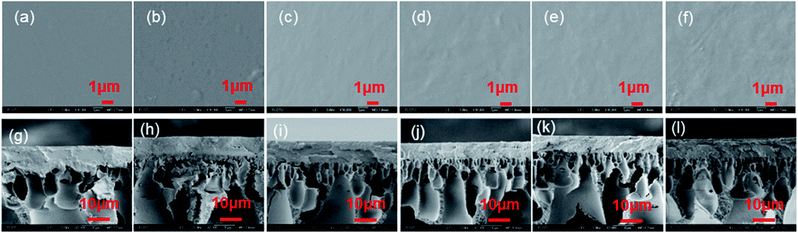 |
| | Fig. 5 The surface (a–f) and cross section (g–l) images of GOP-0.0–GOP-4.0 membranes, respectively. | |
Thermogravimetric analysis (TGA) indicated that the heat resistance and thermal stability of the polymer vary with increasing temperature. The composite GOP membranes were further characterized using TGA analyses under a nitrogen atmosphere. The results are presented in the Fig. 6. The initial weight loss both begin at 250 °C, attributed to the evaporation of physically absorbed water molecules in the membranes. The second stage of weight loss are observed at about 360 °C and 370 °C for the composite GOP-0.0 membranes and the composite GOP-2.0 membranes respectively. The second stage of weight loss is mainly caused by the volatilization of the main chain of PVA and the degradation of unstable oxygen functional groups of GO. Due to the small amount of GO added and only physical effects occurred between molecules, the two thermogravimetric curves does not show significant differences. The end point weight of composite GOP-2.0 membrane at the second stage is slightly higher, which is due to GO has better thermal stability. However, the weight loss of the composite GOP-2.0 membranes in the second stage occurs at a higher temperature, which indicating that the thermal stability of the separation membranes is slightly improved after GO addition.
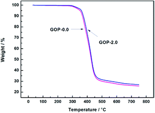 |
| | Fig. 6 TGA curves of GOP-0.0 and GOP-2.0 composite membrane. | |
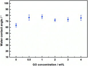
The effect of the hydrophilicity of the composite membranes with different GO additions was investigated by water contact angle (WCA). As shown in the Fig. 7, the contact angle of the pristine PVA membranes is 63.6°(average value), whereas the PVA/GO composite membranes with different GO addition are 76.5°, 77.8°, 72.3°, 73.2° and 75.9° respectively. It can be observed that the contact angle of the membranes increase, and the hydrophilicity decrease after GO addition. This is due to the increases in the network crosslink density of the system after GO addition, which reduces –OH groups in the surface, resulting the increasing of contact angle.
 |
| | Fig. 7 Water contact angles of PVA/GO membranes with different GO loadings. | |
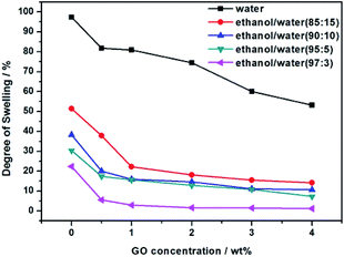
The swelling test results are shown in Fig. 8, the pre-dried membrane samples were immersed in pure water and different ethanol/water binary solutions, respectively. It can be seen that the degree of swelling of the membranes decreases with the increase of the GO addition amount, it is mainly contributed by the hydrogen bonding between GO and PVA, which enhances the membrane rigidity. In addition, as the concentration of ethanol increases, the degree of swelling decreases.
 |
| | Fig. 8 Swelling degree of GOP membranes with different GO addition. | |
3.2 Pervaporation performance for ethanol dehydration
We further studied the pervaporation performance of the composite GOP membranes at feed concentration is 90 wt% ethanol and feed temperature of 45 °C and 69 °C respectively. As shown in Fig. 9a, the total flux of PVA/GO composite membranes are less than PVA membranes. Although the GO nanosheets layer provide an ultra-fast transport pathway to water, the increase of water contact angle makes water harder to enter in membrane, and the increase of PVA crosslinking degree makes it more difficult for water to pass through the membrane, thus the water flux decrease. As can see from Fig. 9b, the separation factor is very high, and in this case, the total flux is determined by the water flux, so total flux decreases. From Fig. 9b, the separation factors first increases and then decreases with increasing GO. When the GO addition increases from 0.0% to 2.0 wt%, the separation factor of the membrane increases sharply, which can be attributed to the cross linking reaction between the GO sheet and the PVA matrix, and the cross linking density increases lead to the membrane more dense. For both experimental temperatures, the separation factor reach the highest value when the amount of GO is 2.0 wt%, which is 1143 for 65 °C and 3059 for 45 °C. Compared with the pristine PVA membranes, the separation factor of all PVA/GO composite membranes are more than 1 000, indicating that GO blending in PVA could significantly enhance the separation factor of the membranes. When GO addition exceed 2.0 wt%, the decrease in the separation factor may be due to the saturation limit of the GO load, and higher than this concentration cause agglomeration of GO, causing defects in the membrane.40–42 The GOP-2.0 membrane is the best selection for further study, due to excellent separation factor and suitable flux. Fig. 10 describes the effect of ethanol concentration on GOP-2.0 performance. According to Fig. 10a, with the increase of ethanol concentration, the total flux decrease notably at experiment temperature, 45 °C and 69 °C. It is owing to that when the mass percentage of water in the feed liquid is decreased, the degree of swelling of the membrane is reduced and the free volume of the membrane is decreased, so that the transport resistance of water and ethanol is increased. At the same time, it is known from Fig. 11 that the ethanol flux is almost constant and close to zero, while the flux of water is large and the trend is almost similar to the total flux. Since the water is preferentially permeated and the separation factor is large, the total flux is determined by the water flux, so the total flux decreases as the ethanol concentration increases. Otherwise, the separation factors of membranes increases with increasing ethanol concentration (Fig. 10b), especially in the high ethanol concentration. This may be caused by that, when the water concentration decreases, the swelling degree of the membrane also decreases, the chain activity spacing of the polymer become smaller, which makes the ethanol diffuse harder that water for its large size.
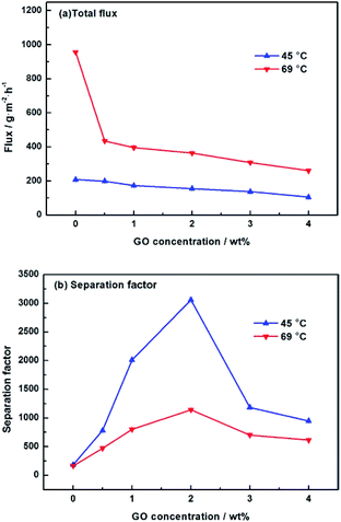 |
| | Fig. 9 Pervaporation performance of GOP membranes. (a) Total flux for membranes under varied GO concentration; (b) separation factor for membranes under varied GO concentration. | |
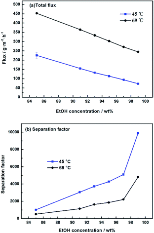 |
| | Fig. 10 Pervaporation performance of GOP-2.0 membrane. Total flux (a) and separation factor (b) for membranes under varied ethanol concentration. | |
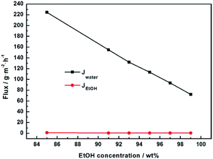 |
| | Fig. 11 Pervaporation performance of GOP-2.0 membrane at 45 °C. Water flux and ethanol flux under varied ethanol concentration. | |
Fig. 12 is the effect of operating temperature on pervaporation performance with 90 wt% ethanol in feed concentration. With the temperature rising from 37 °C to 69 °C, the total flux of the composite GOP-2.0 membranes increase from 103 g m−2 h−1 to 364 g m−2 h−1, and the total flux of the composite GOP-0.0 membranes increase from 139 g m−2 h−1 to 956 g m−2 h−1 (Fig. 12a). Temperature is an important factor affecting the total flux and separation factor. As the feed temperature increases, the vapour pressure in the feed side increases simultaneously and thus the mass transfer driving force of pervaporation increases, which is beneficial to mass transfer. At the same time, the activity and flexibility of the polymer chain are strengthened and the molecular segment spacing increases with increasing temperature, which is benefit for the diffusion of water and ethanol. The above-mentioned combined factors lead to the increase in the total flux. From Fig. 12b, it could be seen that the separation factor first increases and then decreases with increasing temperature. This may be due to when the temperature increases from 37 °C to 45 °C, the activity of polar groups in the membrane is intense, the permeation rate of water and ethanol molecules increases, and the separation effect is obvious. When the temperature exceeds 45 °C, it may be that during the temperature increases, the membrane structure undergoes subtle changes and the macromolecular segments in the membrane are re-aligned, the free volume of the membrane increases and the permeation resistance of the ethanol molecules decreases lead to the permeation rate of ethanol exceeds the rate of penetration of water, thereby reducing the separation factor. At present, there is no clear rule about the relationship between separation factor and temperature. This phenomenon has also appeared in the previous literature.43 Membranes have the best separation factor of 3059 at 45 °C, for the composite GOP-2.0 membranes, much greater than the composite GOP-0.0 membranes (the pristine PVA membranes) in this work, and the PVA membranes obtained in previous studies (Table 3).
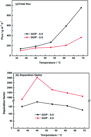 |
| | Fig. 12 Pervaporation performance of GOP-2.0 membrane. Total flux (a) and separation factor (b) for membranes under varied temperature. | |
Table 3 Comparison of pervaporation performance of PVA hybrid membranes for ethanol dehydration
| Membrane |
Temp. (°C) |
Feed, water (wt%) |
Flux (g m−2 h−1) |
Separation factor |
Ref. |
| PVA/g-C3N4 |
75 |
10 |
6332 |
30.7 |
19 |
| PVA/CF (3.5%)-TSA (PVA-3) |
50 |
30 |
127 |
775 |
44 |
| PVA/silk fibroin |
22 |
30 |
∼80 |
23.7 |
45 |
| PVA/ZIF-90 |
30 |
10 |
268 |
1379 |
46 |
| PVA/Fe-DA |
30 |
10 |
995 |
2980 |
41 |
| PVA/SiO2 |
40 |
15 |
145 |
1026 |
47 |
| PVA/N,N-methylene bisacrylamide |
40 |
5 |
353 |
3781 |
48 |
| PVA/ZIF-8-NH2 |
40 |
15 |
158 |
148 |
42 |
| PVA/gelatin |
80 |
10 |
1910 |
∼60 |
49 |
| PVA/H-ZSM5 |
30 |
15 |
182 |
46 |
52 |
| PVA/NaY |
60 |
20 |
300 |
450 |
53 |
| PVA |
40 |
10 |
280 |
104 |
50 |
| PVA |
30 |
20 |
201 |
22 |
51 |
| PVA |
45 |
10 |
200 |
185 |
This work |
| PVA/GO |
45 |
10 |
145 |
3095 |
This work |
| PVA/GO |
45 |
5 |
74 |
4281 |
This work |
4. Conclusions
In this work, PVA/GO nanocomposite membranes were fabricated and used for ethanol dehydration by pervaporation. By GO addition, the crosslinking degree of PVA is effectively increased. When GO content increases from 0.0–4.0 wt%, the PVA crosslinking degree increases, the total flux of the PVA/GO composite membranes decrease, while the separation factors first increases but then decreases, which may be attributed to defects caused by GO aggregation. Of all the PVA/GO membranes, the composite GOP-2.0 membranes had the best separation performance with the separation factor of 3059 and the total flux of 145 g m−2 h−1 at 45 °C and 90 wt% ethanol concentration. The influence of feed concentration and temperature were also conducted. With the increase of feed ethanol concentration, the separation factors of membranes increases significantly, while the total flux decrease. Separation factor 9866 and permeation flux 74 g m−2 h−1 was observed at 45 °C and 99 wt% ethanol concentration. Total flux increase with feed temperature, while separation factor increase first and then decrease. Compared with pristine PVA membranes, permeate flux of PVA/GO nanocomposite membranes decreased a certain amount, but the separation factor were notably increased.
Conflicts of interest
There are no conflicts to declare.
Acknowledgements
The authors greatly appreciate the financial supports of National Natural Science Foundation of China (21736001, 21776153, and 21576150).
References
- C. A. Cardona and O. J. Sanchez, Bioresour. Technol., 2007, 98, 2415–2457 CrossRef CAS PubMed.
- B. Bolto, M. Hoang and Z. Xie, Chem. Eng. Process., 2011, 50, 227–235 CrossRef CAS.
- R. W. Baker, Membr. Technol. and Appli., Wiley, 2012, pp. 3771–3777 Search PubMed.
- P. A. Kober, J. Am. Chem. Soc., 1917, 39, 944–948 CrossRef CAS.
- Y. Sakurada, A. Sueoka and M. Kawahashi, Polym. J., 1987, 19, 501–503 CrossRef CAS.
- S. Qiu, L. Wu and G. Shi, Ind. Eng. Chem. Res., 2010, 49, 11667–11675 CrossRef CAS.
- M. D. Kurkuri, U. S. Toti and T. M. Aminabhavi, J. Appl. Polym. Sci., 2002, 86, 3642–3651 CrossRef CAS.
- K. S. V. K. Rao, M. C. S. Subha, M. Sairam, N. N. Mallikarjuna and T. M. Aminabhavi, J. Appl. Polym. Sci., 2007, 103, 1918–1926 CrossRef CAS.
- Z. Gao, Y. Yue and W. Li, Zeolites, 1996, 16, 70–74 CrossRef.
- N. Durmaz-Hilmioglu, A. E. Yildirim, A. S. Sakaoglu and S. Tulbentci, Chem. Eng. Sci., 2001, 40, 263–267 CAS.
- T. A. Aminabhavi and H. G. Naik, J. Appl. Polym. Sci., 2002, 83, 244–258 CrossRef CAS.
- N. Isiklan and O. Sanli, Chem. Eng. Process., 2005, 44, 1019–1027 CrossRef CAS.
- M. Rafik, A. Mas, M. F. Guimon, C. Guimon, A. Elharfi and F. Schue, Polym. Int., 2003, 52, 1222–1229 CrossRef CAS.
- M. L. Gimenes, L. Liu and X. Feng, J. Membr. Sci., 2007, 295, 71–79 CrossRef CAS.
- B. V. K. Naidua, M. Sairam, K. Raju and T. M. Aminabhavi, J. Membr. Sci., 2005, 260, 142–155 CrossRef.
- S. P. Doguparthy, J. Membr. Sci., 2001, 185, 201–205 CrossRef CAS.
- Z. Arif, N. K. Sethy, P. K. Mishra, S. N. Upadhayay and B. Verma, J. Porous Mater., 2018, 25, 1203–1211 CrossRef CAS.
- Y. P. Wu, Z. L. Xie, D. Ng, S. Shen and Z. H. Zhou, J. Appl. Polym. Sci., 2017, 134 CAS.
- D. Liu, Y. Zhang, J. Jiang, X. Wang, C. Zhang and X. Gu, RSC Adv., 2015, 5, 95866–95871 RSC.
- I. Soroko and A. Livingston, J. Membr. Sci., 2009, 343, 189–198 CrossRef CAS.
- J. Wang, M. Li, S.-Y. Zhou, A. Xue, Y. Zhang, Y.-J. Zhao and J. Zhong, Chem. Eng. Sci., 2018, 181, 237–250 CrossRef CAS.
- J. Wang, M. Li, S. Zhou, A. Xue, Y. Zhang, Y. Zhao, J. Zhong and Q. Zhang, Sep. Purif. Technol., 2017, 188, 24–37 CrossRef CAS.
- P. I. Cheng, P. D. Hong, K. R. Lee, J. Y. Lai and Y. L. Tsai, J. Membr. Sci., 2018, 564, 926–934 CrossRef CAS.
- D. Wang, Q. Lu, M. Wei and E. Guo, J. Appl. Polym. Sci., 2018, 135 Search PubMed.
- H. G. Premakshi, A. M. Sajjan, A. A. Kittur and M. Y. Kariduraganavar, J. Appl.
Polym. Sci., 2015, 132 Search PubMed.
- A. K. Geim, Science, 2009, 324, 1530–1534 CrossRef CAS PubMed.
- J. S. Bunch, S. S. Verbridge, J. S. Alden, A. M. van der Zande, J. M. Parpia, H. G. Craighead and P. L. McEuen, Nano Lett., 2008, 8, 2458–2462 CrossRef CAS PubMed.
- A. K. Geim and K. S. Novoselov, Nat. Mater., 2007, 6, 183–191 CrossRef CAS PubMed.
- G. Liu, W. Jin and N. Xu, Chem. Soc. Rev., 2015, 44, 5016–5030 RSC.
- R. R. Nair, H. A. Wu, P. N. Jayaram, I. V. Grigorieva and A. K. Geim, Science, 2012, 335, 442–444 CrossRef CAS PubMed.
- Y. P. Tang, D. R. Paul and T. S. Chung, J. Membr. Sci., 2014, 458, 199–208 CrossRef CAS.
- S. Mallakpour, A. Abdolmaleki and Z. Khalesi, Polym. Bull., 2018, 75, 1473–1486 CrossRef CAS.
- H. K. Dave and K. Nath, J. Water Process Eng., 2016, 14, 124–134 CrossRef.
- R. L. G. Lecaros, G. E. J. Mendoza, W.-S. Hung, Q.-F. An, A. R. Caparanga, H.-A. Tsai, C.-C. Hu, K.-R. Lee and J.-Y. Lai, Carbon, 2017, 123, 660–667 CrossRef CAS.
- W. S. Hummers and R. E. Offeman, J. Am. Chem. Soc., 1958, 80, 1339 CrossRef CAS.
- C.-H. Tsou, Q.-F. An, S.-C. Lo, M. De Guzman, W.-S. Hung, C.-C. Hu, K.-R. Lee and J.-Y. Lai, J. Membr. Sci., 2015, 477, 93–100 CrossRef CAS.
- N. A. Peppas, Makromol. Chem., 1977, 178, 595–601 CrossRef CAS.
- D. Chen, X. Wang, T. Liu, X. Wang and J. Li, J. Am. Chem. Soc., 2010, 2, 2005–2011 CAS.
- C.-H. Tsou, Q.-F. An, S.-C. Lo, M. De Guzman, W.-S. Hung, C.-C. Hu, K.-R. Lee and J.-Y. Lai, J. Membr. Sci., 2015, 477, 93–100 CrossRef CAS.
- S. P. Dharupaneedi, R. V. Anjanapura, J. M. Han and T. M. Aminabhavi, Ind. Eng. Chem. Res., 2014, 53, 14474–14484 CrossRef CAS.
- Q. Liu, H. Wang, C. Wu, Z. Wei and H. Wang, Sep. Purif. Technol., 2017, 188, 282–292 CrossRef CAS.
- H. Zhang and Y. Wang, AIChE J., 2016, 62, 1728–1739 CrossRef CAS.
- G. Zhang, W. Gu, S. Ji, Z. Liu, Y. Peng and Z. Wang, J. Membr. Sci., 2006, 280, 727–733 CrossRef CAS.
- A. V. Penkova, M. E. Dmitrenko, N. A. Savon, A. B. Missyul, A. S. Mazur, A. I. Kuzminova, A. A. Zolotarev, V. Mikhailovskii, E. Landeranta, D. A. Markelov, K. N. Semenov and S. S. Ermakov, Sep. Purif. Technol., 2018, 204, 1–12 CrossRef CAS.
- J. R. Karp, F. Hamerski and V. R. Silva, Polym. Eng. Sci., 2018, 58, 1879–1887 CrossRef CAS.
- Z. Wei, Q. Liu, C. Wu, H. Wang and H. Wang, Sep. Purif. Technol., 2018, 201, 256–267 CrossRef CAS.
- L. L. Xia, C. L. Li and Y. Wang, J. Membr. Sci., 2016, 498, 263–275 CrossRef CAS.
- J. Li, L. Zhang, J. Gu, Y. Sun and X. Ji, RSC Adv., 2015, 5, 19859–19864 RSC.
- H. Wu, X. Lu, X. Li, Y. Li, C. Zhao and Z. Jiang, Chin. J. Chem. Eng., 2014, 22, 19–27 CrossRef CAS.
- C. K. Yeom, S. H. Lee and J. M. Lee, J. Appl. Polym. Sci., 2001, 79, 703–713 CrossRef CAS.
- B. V. Di Carlo and A. C. Habert, J. Mater. Sci., 2013, 48, 1457–1464 CrossRef.
- D. P. Suhas, T. M. Aminabhavi and A. V. Raghu, Polym. Eng. Sci., 2014, 54, 1774–1782 CrossRef CAS.
- Z. Huang, H. M. Guan, W. L. Tan, X. Y. Qiao and S. Kulprathipanja, J. Membr. Sci., 2006, 276, 260–271 CrossRef CAS.
|
| This journal is © The Royal Society of Chemistry 2019 |
Click here to see how this site uses Cookies. View our privacy policy here. 
 Open Access Article
 This Open Access Article is licensed under a Creative Commons Attribution-Non Commercial 3.0 Unported Licence
 *a,
Xiaohan Chena,
Zhen Shia and
Jiding Lib
*a,
Xiaohan Chena,
Zhen Shia and
Jiding Lib


