 Open Access Article
Three-dimensional “skin-framework” hybrid network as electroactive material platform for high-performance solid-state asymmetric supercapacitor†
Liaoyuan Xia *ab,
Shaoheng Huab,
Xueqin Zhangab,
Le Huangab,
Yu Liaoab,
Yan Qinga,
Yiqiang Wu*a,
Wenping Jianga and
Xihong Lu
 *c
*c
aCollege of Material Science and Engineering, Central South University of Forestry and Technology, Changsha 410004, P. R. China. E-mail: wuyq0506@126.com
bHunan Province Key Laboratory of Materials Surface & Interface Science and Technology, Central South University of Forestry and Technology, Changsha 410004, P. R. China. E-mail: xly1516@126.com
cMOE of the Key Laboratory of Bioinorganic and Synthetic Chemistry, School of Chemistry, Sun Yat-Sen University, Guangzhou 510275, P. R. China. E-mail: luxh6@mail.sysu.edu.cn
First published on 26th April 2019
Abstract
Three-dimensional (3D) electrode materials are ideal candidates for use in fabricating high-performance supercapacitors (SCs), owing to their unique network structure and excellent electrochemical properties. In this study, an aerogel film produced by the freeze-drying self-aggregation of multiwall carbon nanotubes (MWCNTs) and cellulose nanofibers (CNFs) served as the “skin”, and an inter-connected 3D network of nickel foam (NF) as the “framework”, for the fabrication of an MWCNT/CNF-NF (called MCN) hybrid material with a distinct “skin-framework” architecture. Considering the metrics of excellent conductivity, high wettability, binder-free and unique 3D “skin-framework” structure, the MCN hybrid material has great potential as an electroactive material platform in constructing state-of-the-art asymmetric supercapacitor (ASC) electrodes. By incorporating MCN with electroactive manganese dioxide (MnO2) and active carbon (AC), MnO2-MCN and AC-MCN composite electrodes with respective high areal capacitances of 1784.8 (equal to 469.7 F g−1) and 868.8 mF cm−2 (equal to 126.3 F g−1) at 5 mA cm−2 were successfully prepared. Further, both kinds of electrodes exhibited high charge/discharge ability rates and good cycle performance. Moreover, an optimally assembled MnO2-MCN//AC-MCN solid-state ASC was reversibly charged/discharged at voltages as high as 1.8 V and possessed a remarkable volumetric capacity of 9.83 F cm−3 and an energy density of 4.25 mW h cm−3, as well as good cycle stability.
1 Introduction
The rapid development of portable electronics has induced a demand for high-energy-density and lightweight energy storage devices.1–6 Solid-state asymmetric supercapacitors (ASCs), which are a new type of energy storage device, are assembled from positive and negative electrodes of different voltage windows.7–12 They are capable of operation over a wider voltage range, resulting in higher energy and power densities. These remarkable characteristics make them very attractive as ideal energy storage devices for portable electronics. Unlike traditional supercapacitors, a solid-state ASC is typically composed of positive and negative electrodes and a gel electrolyte. Among these components, the performance of the electrodes is very critical to the overall performance of the ASC. Considerable effort has thus been invested in the development of high-performance positive and negative electrodes in solid-state ASCs.13–19Among the different electrode materials that have been recently developed for the fabrication of solid-state supercapacitors, those with unique 3D nanostructures have been found to be very promising, with the nanostructures providing large interfaces for ion diffusion and charge transport.20–24 Nickel foam (NF) has particularly attracted much attention because of its usability as a substrate/current collector and a template for preparing 3D electrodes.25–30 The highly porous 3D structure of NF and the large electrode–electrolyte interface imbue it with improved electrolyte impregnation and reduced ion diffusion distance. In addition, the high conductivity and good mechanical strength of NF make it an ideal current collector for a supercapacitor. Encouraged by these advantages, designers have put considerable effort into the utilization of NF in 3D electrodes.31–33 The material has been used as the template for the development of a number of 3D electrodes with excellent electrochemical properties, through methods such as hydrothermal reaction, electrochemical synthesis, and chemical vapor deposition (CVD).34–37 However, the fabrication processes involve many complex steps, rigorous conditions, and the use of expensive equipment, which have severely impeded the practical application of such electrodes. Furthermore, these methods involve only the deposition or growing of the substances on the NF frameworks and do not favor the uniform distribution of the substances nor enhance their loading capacity owing to the limited specific surface area and poor versatility of NF. Therefore, the use of NF for the simple and scalable fabrication of high-performance 3D electrodes remains a significant challenge.
In this work, we propose a simple, effective, and generally applicable method to rationally design and fabricate advanced 3D electrodes. Unlike conventional methods for producing 3D electrodes by chemical vapor deposition or hydrothermal reaction using an NF template/substrate, the method utilizes an MCN with a 3D “skin-framework” network as the electroactive material platform. On the one hand, NF is used as a skeletal support and affords the electrodes good mechanical properties and superb electrical conductivity. On the other hand, CNF is not only used to facilitate the uniform dispersion of untreated MWCNT but favors the formation of a stable MWCNT/CNF “skin”, thus guaranteeing the introduction of active materials. Consequently, the obtained MnO2-MCN and AC-MCN electrodes not only possess a high areal capacity, but also an outstanding discharge rate and low AC impedance. Moreover, an as-fabricated MnO2-MCN//AC-MCN solid-state ASC device developed with such electrodes can be reversibly charged/discharged at high voltages of up to 1.8 V and has very good high-volume energy and power densities and excellent discharge and cycle performance. Therefore, this work provides a promising strategy for the rational design and fabrication of high-performance 3D electrodes for potential application in portable electronic devices.
2 Materials and method
2.1 Chemicals and materials
All the regents and materials used in this work were used as received without further purification. The CNFs were prepared using our previously described method with minor modifications. MWCNTs (TNIM2, d8-15 nm) were purchased from the Chengdu Institute of Organic Chemistry. AC was supplied by Fujian Xinsen Carbon Limited. Nickel foam was supplied by Changsha Lyrun Material Co., Ltd. Sodium sulfate (Na2SO4), polyvinyl alcohol (PVA), lithium chloride (LiCl), potassium permanganate (KMnO4), hydrochloric acid (HCl), and anhydrous ethanol were obtained from the Sinopharm Chemical Reagent Company. Deionized water was used as prepared.2.2 Preparation of 3D network of MCN and MN hybrid materials
The typical preparation procedure was as follows. Commercial NF measuring 16.0 cm × 13.5 cm was soaked in acetone and ethanol for 6 h and then washed several times with deionized water. It was then dried in a vacuum at 60 °C and weighed, with the weight denoted by W0. The pretreated NF was subsequently immersed in a homogeneously dispersed solution of MWCNT and CNF (wt% = 0.5%) with a mass ratio of 1.5![[thin space (1/6-em)]](https://www.rsc.org/images/entities/char_2009.gif) :
:![[thin space (1/6-em)]](https://www.rsc.org/images/entities/char_2009.gif) 1. After a specified time, the NF was removed from the solution and frozen for 24 h in a freeze-dryer at −50 °C and then vacuum dried at 4.5 Pa for 3 days. This soaking and freeze-drying cycle was repeated 3–5 times, after which the final weight of the NF was taken, with the result denoted by W1. The loading capacity of the MWCNT/CNF per unit area of MCN was then calculated as (W1 − W0)/SNF, where SNF is the area of the NF. The unit area loading capacity was determined to be 5.6 mg cm−2.
1. After a specified time, the NF was removed from the solution and frozen for 24 h in a freeze-dryer at −50 °C and then vacuum dried at 4.5 Pa for 3 days. This soaking and freeze-drying cycle was repeated 3–5 times, after which the final weight of the NF was taken, with the result denoted by W1. The loading capacity of the MWCNT/CNF per unit area of MCN was then calculated as (W1 − W0)/SNF, where SNF is the area of the NF. The unit area loading capacity was determined to be 5.6 mg cm−2.
In order to demonstrate the importance of CNF for the dispersion of MWCNTs and the structural stability of MWCNT/CNF aerogel films, we have prepared MN hybrid materials using the same procedure as MCN. Except for impregnation of MN with ultrasonically dispersed MWCNT solution (wt% = 0.5%).
2.3 Preparation of the MnO2-MCN and AC-MCN 3D electrodes
(1) The preparation of the MnO2-MCN electrode was typically as follows. An MCN measuring 6 cm × 6 cm was used as the platform for loading the MnO2 electroactive material to match the AC-MCN negative electrode. Based on our previous work,24 the MnO2-MCN positive electrodes were prepared using different reaction times (4, 5, 6, and 7 h) and the optimum time was determined for 6 h (Fig. S1†). All the samples were washed using ethanol and deionized water in turn and then vacuum dried at 60 °C. They were subsequently subjected to heat treatment at 220 °C for 2 h.(2) The preparation of the AC-MCN electrode was typically as follows. Firstly, the pretreated and weighed NF (denoted by W0) was immersed in a homogeneously dispersed solution of MWCNT, CNF, and AC (wt% = 1.43%) with a mass ratio of 1![[thin space (1/6-em)]](https://www.rsc.org/images/entities/char_2009.gif) :
:![[thin space (1/6-em)]](https://www.rsc.org/images/entities/char_2009.gif) 1
1![[thin space (1/6-em)]](https://www.rsc.org/images/entities/char_2009.gif) :
:![[thin space (1/6-em)]](https://www.rsc.org/images/entities/char_2009.gif) 8 for a certain time. Then, the NF was removed from the solution, frozen for 24 h in a freeze-dryer at −50 °C, and then vacuum dried at 4.5 Pa for 3 days. This soaking and freeze-drying cycle was repeated 4–6 times, after which the final weight of the NF was taken, with the result denoted by W2. The loading capacity of the MWCNT/CNF/AC per unit area of MCN was then calculated as (W2 − W0)/SNF, where SNF is the area of the NF. The mass per unit area of the load AC was determined to be 6.88 mg cm−2.
8 for a certain time. Then, the NF was removed from the solution, frozen for 24 h in a freeze-dryer at −50 °C, and then vacuum dried at 4.5 Pa for 3 days. This soaking and freeze-drying cycle was repeated 4–6 times, after which the final weight of the NF was taken, with the result denoted by W2. The loading capacity of the MWCNT/CNF/AC per unit area of MCN was then calculated as (W2 − W0)/SNF, where SNF is the area of the NF. The mass per unit area of the load AC was determined to be 6.88 mg cm−2.
2.4 Materials characterization
Scanning electron microscopy (SEM, MIRA3) and transmission electron microscopy (TEM, JEM-2100F) were used for the morphological and microstructural characterization of the electrode materials and electrode sheets. X-ray photoelectron spectrometry (XPS) (Escalab 250Xi, Thermo Fisher Scientific) was used to analyze the chemical composition and element valence state of the electrode surfaces, while atomic absorption spectrometry (ICE3000, Thermo Fisher Scientific) was used to evaluate the loading of MnO2 unto the electrode. The contact angles of Na2SO4 electrolyte (1 M) drops on the surface of the electrode sheets were measured at 25 °C using a contact angle meter (SL150). Nitrogen gas adsorption was measured using a Micromeritics ASAP 2020M analyzer at 77 K, with all the samples degassed at 150 °C in a vacuum for 8 h.2.5 Electrochemical measurements
An electrochemical workstation (CHI 660E) was used to perform electrochemical tests on the electrodes and other components. The electrochemical testing of the electrodes was conducted using a three-electrode system with a 1 M Na2SO4 solution electrolyte, platinum plate counter electrode, and saturated calomel reference electrode. The working electrode had an effective area of 1.0 cm × 1.0 cm. The voltage window of the positive electrode was 0–0.8 V, while that of the negative electrode was −1 to 0 V. To fabricate a solid-state ASC, a LiCl/PVA gel electrolyte was prepared by adding LiCl (4.24 g) and PVA (2 g) into deionized water (20 mL) and heating at 85 °C for 1 h under constant stirring. Two pieces of each of the produced AC-MCN and MnO2-MCN electrodes were immersed into the LiCl/PVA solution for 30 min, and then taken out and assembled together with a cellulose separator sandwiched in between them. Upon completion, the assembly was dried for 1 h at 40 °C and packaged with polyester (PET) film to prevent contamination of the device during the electrochemical characterization testing process.3 Results and discussion
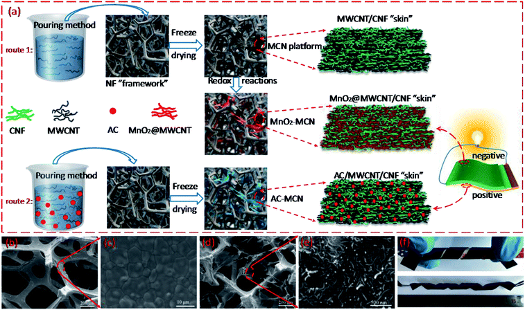
Fig. 1a illustrates the preparation of the 3D MnO2-MCN and AC-MCN electrodes. As shown in Fig. 1a, the MWCNT/CNF solution is first introduced into the 3D NF network (Fig. 1b) by a simple pouring process. Due to the fact that CNF easily forms films, the self-assembled MWCNT/CNF aerogel film formed during freeze-drying was thus randomly stacked onto the NF-network (Fig. 1d) to form the 3D-network “skin-framework” structure of the MCN hybrid material. Benefiting from the high specific surface area and versatility of MWCNT (such as its ability to combine with the metal oxide MnO2 and conductive polymer PPy to improve their discharge rate38,39), CNF has excellent electrolyte adsorption and MWCNT dispersion ability, and NF possesses high electrical conductivity and mechanical strength. Therefore, the large-scale MCN obtained (see Fig. S2†) is promising for use as an electroactive platform for fabrication of high-performance 3D electrodes. Furthermore, the MCN electrode sheet exhibits good flexibility and bending performance (Fig. 1f). In addition, benefiting from the advantages of the MCN platform, we have successfully prepared a high-performance AC-MCN electrode using a similar strategy.To demonstrate the advantages of MCN as an electroactive material platform, its microstructure and morphology were characterized by SEM and TEM. As shown in Fig. 1b, NF has an inter-connected 3D network, which affords MCN a unique 3D porous “skin-framework” structure in which the 3D NF network constitutes the “framework” and the MWCNT/CNF aerogel film is the “skin” (Fig. 1d). This unique structure significantly enhances the conductivity and specific surface area of the MCN platform because the MWCNTs are not only a carrier for electroactive materials (such as MnO2) but also act as a conductive agent. In fact, the N2 adsorption–desorption measurement showed that the specific surface area of MCN was much larger than NF (Fig. S3†). To demonstrate the scalability of MCN as an electroactive platform for the fabrication of high-performance electrodes, MnO2-MCN electrodes were produced by redox reactions (4MnO4− + 3C + H2O → 4MnO2 + CO32− + 2HCO3−).40 As shown in Fig. 2a and b, the MnO2@MWCNT/CNF “skin” is still entirely stacked onto the 3D “framework” of NF after redox reaction with KMnO4 solution. Moreover, a rougher surface loaded with numerous nanoparticles can be observed in the network structure (Fig. 2c). These nanoparticles are assumed to be MnO2 formed in situ at the MWCNT surface during the redox process. In addition, Fig. 2g and h show that MnO2 nanoparticles ranging between 3 and 5 nm are loaded onto the MWCNT surface. To further demonstrate the scalability of MCN as an electroactive platform for the construction of high-performance electrodes, the AC-MCN electrode is prepared by a similar strategy (route 2). As shown in Fig. 2d and e, the AC particles are uniformly distributed in the MWCNT/CNF aerogel film. The high-magnification SEM image illustrates that the MWCNT and CNF were tightly wound on the surface of the AC particles (Fig. 2f, indicated by an arrow), providing an effective pathway for electron transport and ion diffusion in the AC electroactive materials. These results show that, compared with NF, the use of MCN as a platform for electroactive materials is more broadly applicable and offers several structural advantages for the fabrication of high-performance 3D electrodes.
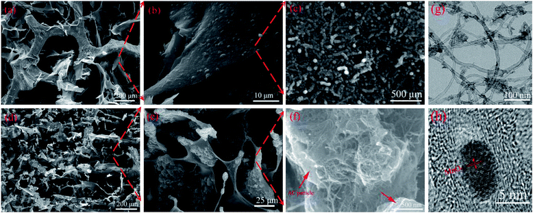 | ||
| Fig. 2 SEM images of (a–c) MnO2-MCN, (d–f) AC-MCN electrodes with different magnifications; and TEM images of (g and h) MnO2-MCN electrode with different magnifications. | ||
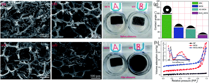
As stated above, the unique 3D porous “skin-framework” network of MCN is the key to its role as a platform for electroactivity materials. This is because the homogeneously distributed untreated MWCNT in the MWCNT/CNF aerogel film is the carrier and conductive pathway of the active materials MnO2 and AC. Hence, the dispersibility of the MWCNT and the structural stability of the MWCNT/CNF “skin” directly affect the performance of MCN as an electroactive platform for fabrication of 3D electrodes. To demonstrate the importance of CNF for the two aforementioned factors, we compared the microstructure and structural stability of the MCN platform and MWCNT-NF hybrid materials (denoted as MN). As shown in Fig. 3a and b, the MWCNT/CNF “skin” of the MCN platform well maintains its thin film morphology before and after ultrasonic treatment in ethanol and water mixed solution, indicating excellent structural stability. Conversely, the MWCNT in MN hybrid barely forms a large-scale and film-like “skin” (Fig. 3c) and has poor structural stability. After ultrasonic treatment, the film-like “skin” obviously peels off from the NF framework (Fig. 3d). The desirable performance of MCN is because CNF not only evenly distributes untreated MWCNT, but its excellent film-forming property is also beneficial to MWCNT/CNF self-assembly to form a structurally stable aerogel film.41 However, without the auxiliary dispersion of CNF, it is difficult to uniformly disperse untreated MWCNT in a water solution, much less achieve the formation of a stable films on the 3D network of NF during freeze-drying. Moreover, after 10 minutes of ultrasound treatment for the MCN sheet, its solution remained clear and transparent (Fig. 3e, Video S1†), whereas after only 1 minute of ultrasound treatment for the MN sheet, its solution turned black (Fig. 3f, Video S1†) owing to the falling off MWCNT from the NF framework. This further demonstrates the superior structural stability of the MWCNT/CNF “skin” stacked onto the MCN platform. In addition, it is worth noting that CNF also effectively improves the wettability of the MnO2-MCN and AC-MCN electrodes (Fig. 3g, Video S2†), thereby facilitating rapid diffusion of the electrolyte and improving the performance of the electrodes.
To further elucidate the advantages of MCN in terms of its microstructure, the porous structures of NF, MCN, and MnO2-MCN were analyzed by N2 adsorption. As shown in Fig. 3h, NF has an atypical type II adsorption–desorption curve. Conversely, those of MCN and MnO2-MCN hybrids are combinations of type I and type IV, indicating the presence of micropores and mesopores.42 In addition, the adsorption–desorption isotherms of MCN and MnO2-MCN have a H3 hysteresis loop at relative pressures of 0.8–1.0, suggesting the existence of macropores.43 The inset of Fig. 3h shows the corresponding pore size distribution (PSD) curves of NF, MCN, and MnO2-MCN obtained by the density functional theory (DFT). A characteristic peak can be observed at 2.5 nm for all the samples, primarily due to the cracks present on the NF surfaces (Fig. 1c). Conversely, MCN and MnO2-MCN have a sharp characteristic peak at 1.6 nm, possibly due to the pores formed by the uniform distribution of MWCNT and CNF (Fig. 1e and 2c). The two materials also have multiple broad characteristic peaks between 9.3 and 34.3 nm, mainly attributed to random pores of various sizes in MCN due to the MWCNT/CNF thin-film stacking. It should be noted that macropores are not reflected in a PSD curves, although they can be verified by SEM observation (Fig. 1d and 2a). These results confirm the higher specific surface area and beneficial porous structure of MCN that enhance its use as an active material platform for the fabrication of high-performance electrodes.
XPS and EDS were used to determine the composition and chemical state of the MnO2-MCN electrode. Fig. S4† and 4 show the full XPS spectrum of the MnO2-MCN electrode and the corresponding Mn 2p and O 1s XPS spectra, respectively. The spectra confirm the presence of manganese oxide in the electrode. Fig. 4a reveals two characteristic peaks of Mn 2p at 653.09 and 642.39 eV, which are identical with those of Mn 2p1/2 and Mn 2p3/2 reported for Mn4+ in the literature.44,45 This indicates the predominant occurrence of Mn as Mn4+ in the electrode. The three characteristic peaks at 533.6, 531.9, and 530.2 eV in the fitted O 1s spectra (Fig. 4b) correspond to Mn–O, Mn–OH, and H–O–H, respectively. This agrees well with the literature46,47 and proves that MnO2 is loading on the MnO2-MCN electrode after the redox reaction process. Fig. 4c shows the distributions of Mn and O in the MnO2-MCN electrode, as determined by EDS. It can be seen that both elements are uniformly distributed in the electrode, further proving the even loading of nano-MnO2 formed in situ by redox processes when MCN is used as the electroactive material platform.
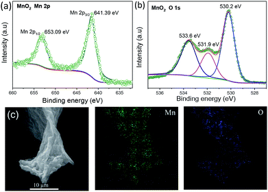 | ||
| Fig. 4 XPS spectra and peak fitting of the MnO2-MCN electrode (a) Mn and (b) O, and (c) EDS maps of Mn and O for the MnO2-MCN electrode. | ||
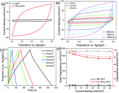
To prove the suitability of MCN for the fabrication of high-performance electrodes, a MnO2-MCN electrode was successfully prepared by redox reaction using MCN as the platform. Fig. 5a compares the cyclic voltammogram (CV) curves of the MCN and MnO2-MCN electrodes for a scanning rate of 100 mV s−1. As expected, the MnO2-MCN electrode exhibits a higher current density than the MCN electrode, its capacitance being mainly due to the loaded nano-MnO2. Further, the galvanostatic charge/discharge (GCD) curves of the two electrodes for a current density of 5 mA cm−2 (Fig. S5a†) clearly shows that the MnO2-MCN electrode has a longer discharge time, further substantiating its excellent capacitive properties. The CV curve of the MnO2-MCN electrode also preserves its quasi-rectangular shape for scanning rates of 5–100 mV s−1 (Fig. 5b), suggesting ideal capacitive characteristics and outstanding discharge performance of the electrode.
As shown in Fig. 5c, the GCD curves of the MnO2-MCN electrode for different current densities all have a symmetrical and triangular shape, revealing a good capacitive behavior and reversible charging–discharging. Fig. 5d shows the relationships between the areal capacity and capacity retention of the MCN and MnO2-MCN electrodes and the discharge current density. The areal capacity of the MnO2-MCN electrode of 1784.8 mF cm−2 (equal to 469.7 F g−1) at a current density of 5 mA cm−2 is obviously much higher than that of the MCN electrode, indicating a much higher discharge performance of the former. The capacity retention of the MnO2-MCN electrode is also as high as 81.7% at a current density of 40 mA cm−2. This is mainly because the uniformly distributed MWCNT in the MnO2-MCN electrode functions as the MnO2 nanoparticles carrier and effectively improves the discharge performance by affording excellent electrical conductivity;24 furthermore, its high specific surface area also facilitates the even loading of MnO2 nanoparticles. From Nyquist impedance plots (Fig. S5b and c†), both the MCN and MnO2-MCN electrodes were observed to have very small impedances (∼1 ohm), attributable to the high conductivity of the 3D network of NF. The MnO2-MCN electrode maintains 92.3% of its initial capacitance after 3000 charge/discharge cycles at a current density of 10 mA cm−2 (Fig. S5d†), demonstrating its good cycle performance. These results provide further evidence of the extraordinary advantages of MCN as an electroactive material platform for fabrication of high-performance 3D electrodes.
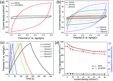
To further evaluate the feasibility of the MCN platform for the fabrication of high-performance 3D electrodes, we prepared an AC-MCN electrode by a similar strategy to match the MnO2-MCN electrode to assemble a solid-state ASC. Fig. 6a shows CV curves of the MCN and AC-MCN electrodes collected at a scanning rate of 100 mV s−1. It can be clearly seen that the current density of the AC-MCN electrode is much higher than that of the MCN electrode. This reveals the superior electrochemical capacity of the AC-MCN electrode. The CV curve of the AC-MCN electrode (Fig. 6b) exhibits a symmetrical quasi-rectangular form when the scan rate increases from 5 to 100 mV s−1, suggesting that the electrode has ideal capacitive characteristics and outstanding discharge performance. Further, the GCD curves of the MCN and AC-MCN electrodes for a current density of 5 mA cm−2 (Fig. S6a†) clearly show that the AC-MCN electrode has a longer discharge time, further substantiating its excellent capacitive properties.
Fig. 6c represents the GCD curves of the AC-MCN electrode collected at various current densities from 5 to 40 mA cm−2. All the GCD curves exhibit good symmetry, further confirming the good capacitive behavior of the AC-MCN electrode. Fig. 6d shows the relationships between the areal capacity and capacity retention rate of the AC-MCN electrode with the discharge current density. Both the areal capacity and discharge performance of the AC-MCN electrode for a given current density are clearly superior. For example, the areal capacity of the AC-MCN electrode for a current density of 5 mA cm−2 is 868.8 mF cm−2 (equal to 126.3 F g−1), which is much higher than that of MCN (53.4 mF cm−2). It should also be noted that the capacity retention rate of the AC-MCN electrode is as high as 74.3% at a current density of 40 mA cm−2. In addition, the AC-MCN electrode exhibits good electrochemical durability (Fig. S6b†); after 3000 charge–discharge cycles at a current density of 10 mA cm−2, the capacitance retention remains above 89.3%. Furthermore, the AC impedance spectrum exhibits a low resistance (∼1 ohm) for this electrode (Fig. S6c and d†), again confirming that the 3D MCN is an excellent platform for fabricating high-performance electrodes.
To assemble the solid-state ASC device, we used the MnO2-MCN as the positive electrode and AC-MCN as the negative electrode. Prior to assembly, it was necessary to consider the charge balance between the anode and cathode during the assembly of the ASC. The balance can be described by the following equation:47
| Cs+ × ΔV+ × S+ = Cs− × ΔV− × S− | (1) |
![[thin space (1/6-em)]](https://www.rsc.org/images/entities/char_2009.gif) :
:![[thin space (1/6-em)]](https://www.rsc.org/images/entities/char_2009.gif) 1. Using the stable potential windows of the AC-MCN and MnO2-MCN electrodes of −1.0 to 0.0 V and 0.0–0.8 V, respectively (Fig. 7a), the operating voltage of the as-fabricated MnO2-MCN//AC-MCN solid-state ASC was determined to be as high as 1.8 V (Fig. 7b). Fig. S7a† shows the CV curves of the ASC device for various scanning rates and a voltage window of 1.8 V. All the curves can be observed to be symmetric and rectangle-like, indicative of good reaction reversibility and typical capacity characteristics of the ASC. This would enable the development of solid-state ASC devices with high energy densities.
1. Using the stable potential windows of the AC-MCN and MnO2-MCN electrodes of −1.0 to 0.0 V and 0.0–0.8 V, respectively (Fig. 7a), the operating voltage of the as-fabricated MnO2-MCN//AC-MCN solid-state ASC was determined to be as high as 1.8 V (Fig. 7b). Fig. S7a† shows the CV curves of the ASC device for various scanning rates and a voltage window of 1.8 V. All the curves can be observed to be symmetric and rectangle-like, indicative of good reaction reversibility and typical capacity characteristics of the ASC. This would enable the development of solid-state ASC devices with high energy densities.
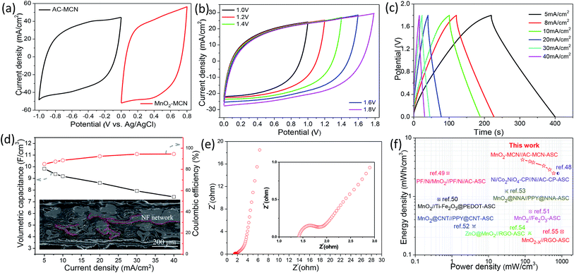 | ||
| Fig. 7 (a) CV curves of the AC-MCN and MnO2-MCN electrodes obtained using a scanning rate of 50 mV s−1; (b) CV curves of the solid-state MnO2-MCN//AC-MCN ASC device collected at a scanning rate of 50 mV s−1 and different voltage windows; (c) GCD curves of the ASC device for current densities of 5–40 mA cm−2; (d) volumetric capacity and coulombic efficiency as a function of the current density, and (inset) cross-sectional SEM image of the ASC device; (e) Nyquist plots of the ASC device; and (f) comparison of Ragone plots of the ASC device with those of other devices in the literature.48–55 | ||
Fig. 7c shows GCD curves of the MnO2-MCN//AC-MCN ASC device for different current densities. The symmetrical and triangular shape curves demonstrate the outstanding capacity properties and rapid charging/discharging of the device. Fig. S7b† shows the GCD curves of the device for voltage windows of 1.0–1.8 V and a discharge current density of 10 mA cm−2. All the curves are roughly symmetrical and triangular, further confirming the ASC device as an ideal capacitor. As can be seen from Fig. 7d, the MnO2-MCN//AC-MCN ASC device has its highest volumetric capacitance of 9.83 F cm−3 under a discharge current density of 5 mA cm−2 and voltage window of 1.8 V, substantially higher than recently reported values for other ASCs such as a Ni/Co2NiO4-CP//Ni/AC-CP-ASC (4.48 F cm−3 at 4 mA cm−2),48 PF/Ni/MnO2//PF/Ni/AC ASC (1.4 F cm−3 at 2.5 mA cm−2),49 MnO2//Ti–Fe2O3@PEDOT ASC (1.15 F cm−3 at 1 mA cm−2),50 MnO2//Fe2O3 ASC (1.5 F cm−3 at 2 mA cm−2),51 and MnO2@CNT//PPy@CNT ASC (2.2 F cm−3 at 2 mA cm−2).52 When the current density increases from 5 to 40 mA cm−2, the capacity retention of the MnO2-MCN//AC-MCN ASC device is maintained as high as 75.4%, validating its excellent discharge performance. This is mainly because the MnO2-MCN and AC-MCN electrodes consist of a unique multilayer structure (Fig. 7d and S8†), with the NF-formed 3D network conductive path between the multilayer structures also affording the electrodes excellent electrical conductivity. As can be seen from Fig. S7c,† the ASC retains 81.6% of its initial capacitance after 5000 charge/discharge cycles, revealing a good cycle performance. The electrochemical impedance spectra of the assembled ASC device were analyzed to evaluate the electrochemical behavior. As shown in Fig. 7e, the Nyquist impedance plot of the MnO2-MCN//AC-MCN ASC is almost parallel to the imaginary linear axis, once again indicating ideal capacitance properties of the device. The charge-transfer resistance is also very small (∼1 ohm), implying rapid charge transfer.
Fig. 7f compares the volumetric power and energy density of the assembled MnO2-MCN//AC-MCN ASC device with those of other previously reported ASC devices.48–54 Notably, the present ASC exhibits a high energy density, high power density, and excellent discharge performance. For example, its volumetric energy is as high as 4.25 mW h cm−3 at a current density of 5 mA cm−2, higher than those of many of the other ASC devices such as the Ni/Co2NiO4-CP//Ni/AC-CP ASC (2.48 mW h cm−3 at 4 mA cm−2),48 PF/Ni/MnO2//PF/Ni/AC ASC (0.78 mW h cm−3 at 2.5 mA cm−2),49 MnO2//Ti–Fe2O3@PEDOT ASC (0.89 mW h cm−3 at 1 mA cm−2),50 MnO2//Fe2O3 ASC (0.55 mW h cm−3 at 2 mA cm−2),51 MnO2@CNT//PPy@CNT ASC (0.31 mW h cm−3 at 2 mA cm−2),52 MnO2@NNA//PPy@NNA ASC (1.23 mW h cm−3 at 1 mA cm−2),53 ZnO@MnO2//RGO ASC (0.234 mW h cm−3 at 2 mA cm−2),54 and MnO2−X//RGO-ASC (0.25 mW h cm−3 at 2 mA cm−2).55 Even for a current density of 40 mA cm−2, the volumetric energy and power density of the present ASC were still as much as 2.50 mW h cm−3 and 598.85 mW cm−3, respectively. Two of the present ASCs (dimension: 1 cm × 1 cm) connected in series were used to continuously light up a 3.0 V LED lamp (Fig. S7c,† inset), which also demonstrates the high energy density of the as-fabricated ASC device. The above results demonstrate the very promising potential of MnO2-MCN and AC-MCN electrodes prepared using an MCN electroactive material platform for use in the development of high-performance ASC devices.
4 Conclusions
In summary, a method for using MCN with a 3D network “skin-framework” structure as the platform of the electroactive materials of high-performance MnO2-MCN and AC-MCN 3D electrodes was proposed in this work. Compared with conventional methods such as the use of CVD and hydrothermal reaction, the proposed method is simple, involves mild reaction conditions, effective, inexpensive, and scalable. Benefiting from the unique 3D “skin-framework” architecture of MCN, the obtained electrodes offer the following advantages: (1) superb electrical conductivity and rapid electrolyte diffusion and (2) stable “skin” and large interfacial contact area, which provide a convenient and effective platform for the electroactive materials. In addition, the as-obtained MnO2-MCN anode and AC-MCN cathode exhibit high areal capacities and excellent electrical conductivities and rate performance. The MnO2-MCN and AC-MCN electrodes exhibited capacitances of 1784.8 and 868.8 mF cm−2, respectively, for a current density of 5 mA cm−2. A 1.8 V solid-state ASC assembled using the electrodes also exhibited a very high volumetric capacity of 9.83 F cm−3 and maximum energy density of 4.25 mW h cm−3. These findings confirm the very high potential of using electrodes based on MCN platforms for the development of high-energy ASCs for portable electronics.Conflicts of interest
There are no conflicts to declare.Acknowledgements
L. Y. Xia and S. H. Hu contributed equally to this work. The authors are grateful for the support of the National Natural Science Foundation of China (31530009, 31200438), National Key R&D Program of China (2017YFD0600804), Hunan Provincial Natural Science Foundation of China (2015JJ2199).Notes and references
- L. Dong, C. Xu, Y. Li, Z. Pan, G. Liang, E. Zhou, F. Kang and Q. H. Yang, Adv. Mater., 2016, 28, 9313–9319 Search PubMed.
- L. Dong, C. Xu, Y. Li, C. Wu, B. Jiang, Q. Yang, E. Zhou, F. Kang and Q. H. Yang, Adv. Mater., 2016, 28, 1675–1681 Search PubMed.
- Z. S. Wu, K. Parvez, S. Li, S. Yang, Z. Liu, S. Liu, X. Feng and K. Mullen, Adv. Mater., 2015, 27, 4054–4061 CrossRef CAS PubMed.
- X. Wang, X. Lu, B. Liu, D. Chen, Y. Tong and G. Shen, Adv. Mater., 2014, 26, 4763–4782 CrossRef CAS PubMed.
- H. Wu, Y. Huang, F. Xu, Y. Duan and Z. Yin, Adv. Mater., 2016, 28, 9881–9919 CrossRef CAS PubMed.
- L. Wen, F. Li and H. M. Cheng, Adv. Mater., 2016, 28, 4306–4337 CrossRef CAS PubMed.
- S. Liu, Y. Yin, K. S. Hui, K. N. Hui, S. C. Lee and S. C. Jun, Adv. Sci., 2018, 5, 1800733 CrossRef PubMed.
- D. Ghosh, J. Lim, R. Narayan and S. O. Kim, ACS Appl. Mater. Interfaces, 2016, 8, 22253–22260 Search PubMed.
- D. Yu, K. Goh, Q. Zhang, L. Wei, H. Wang, W. Jiang and Y. Chen, Adv. Mater., 2014, 26, 6790–6797 Search PubMed.
- K. P. Annamalai, L. Liu and Y. Tao, Adv. Mater. Interfaces, 2017, 4, 1700219 Search PubMed.
- P. Wu, S. Cheng, M. Yao, L. Yang, Y. Zhu, P. Liu, O. Xing, J. Zhou, M. Wang, H. Luo and M. Liu, Adv. Funct. Mater., 2017, 27, 1702160 Search PubMed.
- X. Lu, M. Yu, G. Wang, Y. Tong and Y. Li, Energy Environ. Sci., 2014, 7, 2160–2181 Search PubMed.
- J.-X. Feng, S.-H. Ye, X.-F. Lu, Y.-X. Tong and G.-R. Li, ACS Appl. Mater. Interfaces, 2015, 7, 11444–11451 CrossRef CAS PubMed.
- C. Yang, J. Shen, C. Wang, H. Fei, H. Bao and G. Wang, J. Mater. Chem. A, 2014, 2, 1458–1464 RSC.
- A. Bora, K. Mohan, S. Doley and S. K. Dolui, ACS Appl. Mater. Interfaces, 2018, 10, 7996–8009 Search PubMed.
- Z. Gao, W. Yang, J. Wang, N. Song and X. Li, Nano Energy, 2015, 13, 306–317 Search PubMed.
- Z. Pan, Y. Qiu, J. Yang, F. Ye, Y. Xu, X. Zhang, M. Liu and Y. Zhang, Nano Energy, 2016, 26, 610–619 CrossRef CAS.
- L. Wang, H. Yang, X. Liu, R. Zeng, M. Li, Y. Huang and X. Hu, Angew. Chem., Int. Ed., 2017, 56, 1105–1110 Search PubMed.
- F. Zhang, T. Zhang, X. Yang, L. Zhang, K. Leng, Y. Huang and Y. Chen, Energy Environ. Sci., 2013, 6, 1623–1632 RSC.
- T. T. Nguyen, J. Balamurugan, N. H. Kim and J. H. Lee, J. Mater. Chem. A, 2018, 6, 8669–8681 Search PubMed.
- K. Ghosh, C. Y. Yue, M. M. Sk and R. K. Jena, ACS Appl. Mater. Interfaces, 2017, 9, 15350–15363 CrossRef CAS.
- Y. Yang, G. Ruan, C. Xiang, G. Wang and J. M. Tour, J. Am. Chem. Soc., 2014, 136, 6187–6190 CrossRef CAS PubMed.
- Y. Shao, M. F. El-Kady, C.-W. Lin, G. Zhu, K. L. Marsh, J. Y. Hwang, Q. Zhang, Y. Li, H. Wang and R. B. Kaner, Adv. Mater., 2016, 28, 6719–6726 Search PubMed.
- L. Xia, X. Li, X. Wu, L. Huang, Y. Liao, Y. Qing, Y. Wu and X. Lu, J. Mater. Chem. A, 2018, 6, 17378–17388 RSC.
- X. Yang, Z. Lin, J. Zheng, Y. Huang, B. Chen, Y. Mai and X. Feng, Nanoscale, 2016, 8, 8650–8657 Search PubMed.
- H. Jiang, X. Cai, Y. Qian, C. Zhang, L. Zhou, W. Liu, B. Li, L. Lai and W. Huang, J. Mater. Chem. A, 2017, 5, 23727–23736 Search PubMed.
- G. Zhou, L. Li, C. Ma, S. Wang, Y. Shi, N. Koratkar, W. Ren, F. Li and H.-M. Cheng, Nano Energy, 2015, 11, 356–365 CrossRef CAS.
- Y. He, W. Chen, X. Li, Z. Zhang, J. Fu, C. Zhao and E. Xie, ACS Nano, 2013, 7, 174–182 CrossRef CAS.
- V. H. Nguyen and J.-J. Shim, J. Power Sources, 2015, 273, 110–117 CrossRef CAS.
- C. Wu, J. Cai, Q. Zhang, X. Zhou, Y. Zhu, P. K. Shen and K. Zhang, ACS Appl. Mater. Interfaces, 2015, 7, 26512–26521 CrossRef CAS.
- J. Wang, D. Chao, J. Liu, L. Li, L. Lai, J. Lin and Z. Shen, Nano Energy, 2014, 7, 151–160 CrossRef CAS.
- D. Kong, C. Cheng, Y. Wang, J. I. Wong, Y. Yang and H. Y. Yang, J. Mater. Chem. A, 2015, 3, 16150–16161 RSC.
- H. Huang, Y. Tang, L. Xu, S. Tang and Y. Du, ACS Appl. Mater. Interfaces, 2014, 6, 10248–10257 CrossRef CAS PubMed.
- X. Xiong, D. Ding, D. Chen, G. Waller, Y. Bu, Z. Wang and M. Liu, Nano Energy, 2015, 11, 154–161 CrossRef CAS.
- K. Xu, W. Li, Q. Liu, B. Li, X. Liu, L. An, Z. Chen, R. Zou and J. Hu, J. Mater. Chem. A, 2014, 2, 4795–4802 RSC.
- C. Zhou, Y. Zhang, Y. Li and J. Liu, Nano Lett., 2013, 13, 2078–2085 CrossRef CAS PubMed.
- G. Zhu, Z. He, J. Chen, J. Zhao, X. Feng, Y. Ma, Q. Fan, L. Wang and W. Huang, Nanoscale, 2014, 6, 1079–1085 RSC.
- R. T. Vinny, K. Chaitra, K. Venkatesh, N. Nagaraju and N. Kathyayini, J. Power Sources, 2016, 309, 212–220 CrossRef CAS.
- K. Liang, T. Gu, Z. Cao, X. Tang, W. Hu and B. Wei, Nano Energy, 2014, 9, 245–251 CrossRef CAS.
- J.-G. Wang, F. Kang and B. Wei, Prog. Mater. Sci., 2015, 74, 51–124 CrossRef CAS.
- N. Lavoine and L. Bergström, J. Mater. Chem. A, 2017, 5, 16105–16117 RSC.
- L. Xia, X. Li, Y. Wu and M. Rong, ACS Sustainable Chem. Eng., 2015, 3, 1724–1731 CrossRef CAS.
- L. Xia, X. Li, F. Zhu, S. Hu and L. Huang, J. Phys. Chem. C, 2017, 121, 20279–20286 CrossRef CAS.
- S. Zhu, L. Li, J. Liu, H. Wang, T. Wang, Y. Zhang, L. Zhang, R. S. Ruoff and F. Dong, ACS Nano, 2018, 12, 1033–1042 CrossRef CAS.
- Z. Zhang, F. Xiao, L. Qian, J. Xiao, S. Wang and Y. Liu, Adv. Energy Mater., 2014, 4, 1400064 CrossRef.
- Y. Cheng, S. Lu, H. Zhang, C. V. Varanasi and J. Liu, Nano Lett., 2012, 12, 4206–4211 CrossRef CAS.
- Z. Pan, M. Liu, J. Yang, Y. Qiu, W. Li, Y. Xu, X. Zhang and Y. Zhang, Adv. Funct. Mater., 2017, 27, 1701122 CrossRef.
- J.-X. Feng, S.-H. Ye, A.-L. Wang, X.-F. Lu, Y.-X. Tong and G.-R. Li, Adv. Funct. Mater., 2014, 24, 7093–7101 CrossRef CAS.
- L. Zhang, P. Zhu, F. Zhou, W. Zeng, H. Su, G. Li, J. Gao, R. Sun and C. P. Wong, ACS Nano, 2016, 10, 1273–1282 CrossRef CAS.
- C. Xu, Z. Li, C. Yang, P. Zou, B. Xie, Z. Lin, Z. Zhang, B. Li, F. Kang and C. P. Wong, Adv. Mater., 2016, 28, 4105–4110 CrossRef CAS.
- Y. Zeng, Y. Han, Y. Zhao, Y. Zeng, M. Yu, Y. Liu, H. Tang, Y. Tong and X. Lu, Adv. Energy Mater., 2015, 5, 1402176 CrossRef.
- P. Yang, Y. Ding, Z. Lin, Z. Chen, Y. Li, P. Qiang, M. Ebrahimi, W. Mai, C. P. Wong and Z. L. Wang, Nano Lett., 2014, 14, 731–736 CrossRef CAS PubMed.
- Q. Tang, M. Chen, C. Yang, W. Wang, H. Bao and G. Wang, ACS Appl. Mater. Interfaces, 2015, 7, 15303–15313 CrossRef CAS.
- W. Zilong, Z. Zhu, J. Qiu and S. Yang, J. Mater. Chem. C, 2014, 2, 1331–1336 RSC.
- T. Zhai, S. Xie, M. Yu, P. Fang, C. Liang, X. Lu and Y. Tong, Nano Energy, 2014, 8, 255–263 CrossRef CAS.
Footnote |
| † Electronic supplementary information (ESI) available. See DOI: 10.1039/c9ra01164a |
| This journal is © The Royal Society of Chemistry 2019 |

