
 Open Access Article
 This Open Access Article is licensed under a Creative Commons Attribution-Non Commercial 3.0 Unported Licence
Synthesis of nano-sized urchin-shaped LiFePO4 for lithium ion batteries†
Changjin Yang‡
a,
Doo Jin Lee‡b,
Hyunhong Kim‡a,
Kangyong Kima,
Jinwhan Jooa,
Won Bae Kim b,
Yong Bae Songc,
Yoon Seok Jungc and
Jongnam Park*a
b,
Yong Bae Songc,
Yoon Seok Jungc and
Jongnam Park*a
aSchool of Energy and Chemical Engineering, Ulsan National Institute of Science and Technology (UNIST), Ulsan 44919, Republic of Korea. E-mail: jnpark@unist.ac.kr
bDepartment of Chemical Engineering, Pohang University of Science and Technology, Pohang 790-784, Republic of Korea
cDepartment of Energy Engineering, Hanyang University, Seoul 04763, Republic of Korea
First published on 3rd May 2019
Abstract
In this article, the facile synthesis of sea urchin-shaped LiFePO4 nanoparticles by thermal decomposition of metal-surfactant complexes and application of these nanoparticles as a cathode in lithium ion secondary batteries is demonstrated. The advantages of this work are a facile method to synthesize interesting LiFePO4 nanostructures and its synthetic mechanism. Accordingly, the morphology of LiFePO4 particles could be regulated by the injection of oleylamine, with other surfactants and phosphoric acid. This injection step was critical to tailor the morphology of LiFePO4 particles, converting them from nanosphere shapes to diverse types of urchin-shaped nanoparticles. Electron microscopy analysis showed that the overall dimension of the urchin-shaped LiFePO4 particles varied from 300 nm to 2 μm. A closer observation revealed that numerous thin nanorods ranging from 5 to 20 nm in diameter were attached to the nanoparticles. The hierarchical nanostructure of these urchin-shaped LiFePO4 particles mitigated the low tap density problem. In addition, the nanorods less than 20 nm attached to the edge of urchin-shaped nanoparticles significantly increased the pathways for electronic transport.
Introduction
Nanostructured materials have attracted great attention in the field of lithium ion batteries (LIBs).1–7 In general, active materials having nanostructures can be critical components in high power density applications such as plug-in hybrid electric vehicles (PHEVs) and energy storage/conversion systems. Numerous candidate materials with nano-architectures have been used as electrodes (both cathode and anode), separators, and electrolytes8 to improve the performance of LIBs, and significant progress has been achieved.It has been generally accepted that the selection of electrode materials is one of the most important aspects for overall performance of LIBs. Therefore, considerable interest has been devoted to the development and improvement of electrode materials.9 Even though many electrode materials have been extensively tested, the choice of appropriate electrode materials is still a challenging task. The most widely used cathode is lithium oxide, while graphite has been widely employed as the anode.
Recently, lithium iron phosphate (LiFePO4 or LFP), having an olivine structure, has attracted attention as a potential cathode material for LIBs due to a high theoretical capacity (170 mA h g−1), high safety, eco-friendly materials, and low cost.10–26 LiFePO4 is composed of eco-friendly Fe and PO4, and the PO4 tetrahedra of LiFePO4 provide excellent thermal stability due to strong covalent bonding with oxygen. However, the continuous structures of the FeO6 octahedra are separated by the PO4 tetrahedra. As a result, LiFePO4 has poor electrical conductivity and a low lithium ion diffusion coefficient.27–30 To address these issues, several strategies such as morphology control,31–34 surface coating of an additional layer,35–38 and use of conductive additives39–41 have been attempted. Recently, graphene or graphene oxide have become effective additive materials to improve the electrical conductivity of LFP cathodes.42–46
Conventionally, the low conductivities of LiFePO4 can be improved by applying a carbon layer on the surface or by nano-sizing the LiFePO4, reducing the lithium ion diffusion length.35–38 Meng and co-workers synthesized a nano-dendritic LiFePO4 structure by controlling the ethylene glycol/water ratio with dodecyl benzene sulphonic acid sodium (SDBS) as a surfactant under hydrothermal conditions.47 The obtained non-uniform nano-dendritic particles were much larger than 10 μm in size. Moreover, predominantly agglomerated structures were observed. Goodenough and co-workers have demonstrated that the three-dimensional porous microspheres of LiFePO4 are composed of nanoplates or nanoparticles, which have a stable structure, high tap density, volumetric energy density, and outstanding rate capability.48
The LiFePO4 nanoparticles have a large surface area to volume ratio, which enhances the intimate contact between the electrolyte and the electrodes. This phenomenon brings about two opposing outcomes. The reaction kinetics are rapid, yet side reactions are promoted. While the down-sizing strategy can elevate rate capability and power performance, problems of low tap density and suppressed volumetric energy density still exist.49,50
To resolve this issue efficiently, we developed a simple and straightforward method to synthesize highly uniform, nano-sized, urchin-shaped LiFePO4 particles with hierarchical structures.51 To this end, metal-surfactant complexes were decomposed thermally, unlike was done in previously routine methods such as co-precipitation. In a modified thermal heating method, highly crystalline urchin-shaped LiFePO4 nanostructures were fabricated at relatively low temperature. The average dimension of the obtained urchin-shaped LiFePO4 materials was from hundreds of nanometers to several micrometers, while the average size of individual nano-facets of the prepared urchin-shaped LiFePO4 nanostructures ranged from 5 to 10 nm. To the best of our knowledge, this is the smallest size of LiFePO4 nanomaterials that has been reported. Finally, we determined efficiency and cyclic performance of the nanomaterial by electrochemical measurements.
Experimental section
Materials
Lithium carbonate, iron(III)-acetylacetonate, oleylamine (technical grade, 70%), oleic acid (technical grade, 90%), phosphoric acid 85 wt% in H2O (H3PO4) and tetraethyleneglycol (TEG) were purchased from Sigma-Aldrich and used without purification. Acetone and hexane were purchased from Samchun Chemical (Korea) and used as received.Synthesis of nano-sized urchin-shaped LiFePO4
Synthesis was carried out under an argon atmosphere using standard Schlenk line techniques. First, lithium carbonate (1.5 mmol) and iron(III)-acetylacetonate (1.5 mmol) were used as starting materials, with oleylamine (11.5 mmol) and 10 mL of TEG used as a surfactant and solvent, respectively, were placed in a three neck flask equipped with a condenser, magnetic stirrer, thermocouple, and a heating mantle. First, the mixed solution was degassed at room temperature for 5 to 10 min. Then the solution was heated to 200 °C at a rate of 5 °C min−1 over 35 min, with vigorous magnetic stirring. The reaction mixture was kept at this temperature for 1 h. After this step, H3PO4 (1.5 mmol) and oleylamine (2 mmol) were injected into the mixture. Subsequently, the temperature was increased from 200 °C to 260 °C at a rate of 5 °C min−1. After maintaining for 1.5 h at the same temperature, the reaction was completed. The solution was cooled to room temperature, and acetone and hexane were added to the solution. The solution was then centrifuged at 3000 rpm for 5 min to precipitate the particles. The separated precipitate was washed again with acetone and hexane.Characterization
The phases of the products were characterized by a X-ray diffractometer (XRD, Rigaku, Japan) employing a scan rate of 2° min−1 in the 2θ range from 10° to 80° with a Cu-Kα radiation (λ = 1.540561 Å), operated at 40 kV and 300 mA. Scanning electron microscopy (SEM) images were taken with an S-4800 field emission scanning electron microscope (FESEM, Hitachi, Japan) at an acceleration voltage of 15 kV. High-resolution transmission electron microscopy (HRTEM) images were taken with a JEOL JEM-2100 electron microscope with an acceleration voltage of 200 kV.Electrochemical investigation
A composite electrode used for electrochemical measurements was prepared as follows: 15 wt% of poly(vinylidene fluoride) (PVDF) was first dissolved in N-methylpyrrolidone (NMP). A mixture containing 70 wt% of LiFePO4 and 15 wt% of Super P carbon was then added into the solution, and the suspension was mixed two times for 15 min. Subsequently, the slurry was coated onto Al foil and dried at 80 °C for 12 h under vacuum. The area density of the active material was around 1.77 mg cm−2. Lithium metal was used as an anode and a Celgard 2502 membrane was used as a separator. The electrolyte was a 1.3 M LiPF6 solution of ethylene carbonate (EC), ethyl methyl carbonate (EMC), and dimethyl carbonate (DMC) in a ratio of 3![[thin space (1/6-em)]](https://www.rsc.org/images/entities/char_2009.gif) :4:3 by volume. CR2016 coin type cells were assembled in an argon-filled glove box. Charge–discharge performance of the CR2016 coin cells was evaluated at 2.5–4.0 V with a Wonatech 3.1 battery test system (Wonatech Corp., Korea). The electrochemical impedance spectroscopy (EIS) data were collected in the range of 0.01 Hz and 7 MHz with an amplitude of 20 mV. For the EIS measurements, the cells were discharged to 3.2 V (vs. Li/Li+) at 40 mA g−1, followed by rest for 3 hours.
:4:3 by volume. CR2016 coin type cells were assembled in an argon-filled glove box. Charge–discharge performance of the CR2016 coin cells was evaluated at 2.5–4.0 V with a Wonatech 3.1 battery test system (Wonatech Corp., Korea). The electrochemical impedance spectroscopy (EIS) data were collected in the range of 0.01 Hz and 7 MHz with an amplitude of 20 mV. For the EIS measurements, the cells were discharged to 3.2 V (vs. Li/Li+) at 40 mA g−1, followed by rest for 3 hours.
Results and discussion
Synthesis and characterization
We employed direct thermal decomposition of metal-surfactant complexes to produce well-defined, urchin-shaped LiFePO4 nanostructures. The overall scheme for the synthetic procedure is exhibited in Scheme 1. Nano-sized LiFePO4 with diverse morphologies were obtained by varying several process parameters such as temperature profile, type and amount of feeding constituents, and the injection point of H3PO4. By controlling the precise synthesis conditions of metal oxide nanocrystals, it was feasible to determine the optimal process window for the synthesis of LiFePO4 nanostructures. In addition, it was possible to understand the optimal process window for the synthesis of LiFePO4 nanostructures and the subtle interplay between process parameters. The relevant information about precursors, surfactants, stoichiometry, and processing conditions to produce each shape are summarized in Scheme 1. | ||
| Scheme 1 Synthesis illustration and procedure of spherical LiFePO4 nanoparticles (NS-LFP), urchin-shaped LiFePO4 (NU-LFP) nanoparticles, discrete urchin-shaped LiFePO4 nanoparticles (DNU-LFP), and circular urchin-shaped LiFePO4 nanoparticles (CNU-LFP). | ||
In general, oleylamine, oleic acid, and octadecylamine were used as surfactants, along with lithium carbonate, iron(III)-acetylacetonate, and H3PO4 precursors. It was found that two main control factors were important to exclusively obtain LiFePO4 nanomaterials with an identical morphology. First, the injection point of the H3PO4/oleylamine at the end of 1st aging step at 200 °C was critical to form spherical (NS-LFP) or urchin-shaped LiFePO4 particles (NU-LFP). Second, a change in the type and amount of surfactant could convert the morphology of urchin-shaped LiFePO4 nanoparticles (NU-LFP) to fully-grown circular urchin-shaped LiFePO4 nanoparticles (CNU-LFP). Intermediate discrete nanostructures were observed when only H3PO4 was injected after 1st aging step (DNU-LFP).
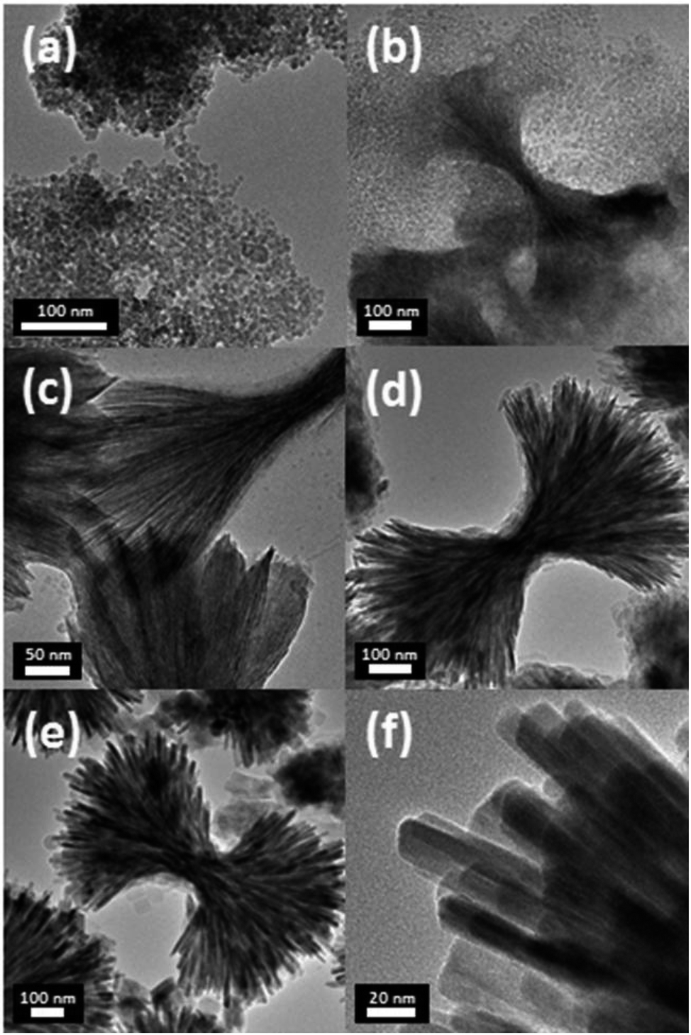
Fig. 1 shows transmission electron microscopy images of the obtained LiFePO4 nanomaterials displaying distinct morphologies. NS-LFP were exclusively synthesized in a uniform size distribution when the metal precursors, oleylamine, and oleic acid were mixed in a starting solution (Fig. 1a). In this case, the solution was heated directly to 260 °C without conducting the 1st aging step at 200 °C. As confirmed by the image, NS-LFP is nearly spherical nanoparticle with an average diameter of 5 to 10 nm. Repetitive XRD analyses indicated that the NS-LFP was mainly composed of Li3PO4 and LiFePO4, as shown in Fig. 2a. This was because a relatively small amount of Li+ from lithium carbonate reacted with PO43− ions from H3PO4, due to a strong binding force between the Li+ and PO43− ions during the thermal decomposition of metal precursors.
 | ||
| Fig. 1 TEM images of (a) NS-LFP; (b) NU-LFP, oleylamine and H3PO4 were injected at the end of the 1st aging at 200 °C; (c) DNU-LFP, only H3PO4 was injected at the end of the 1st aging at 200 °C; (d) CNU-LFP, 1.38 mmol of octadecylamine and 10.12 mmol of oleylamine were mixed with metal precursors, and only H3PO4 was injected at the end of the 1st aging at 200 °C and then aged for 3 h at 260 °C. | ||
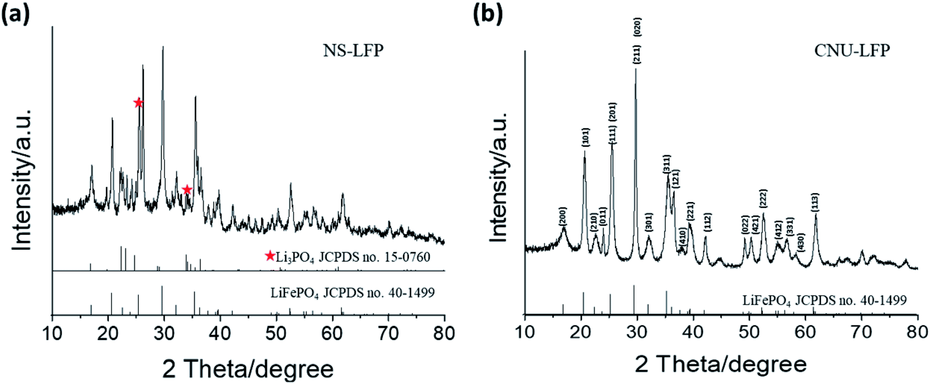 | ||
| Fig. 2 XRD characterization of (a) spherical LiFePO4 nanoparticles (NS-LFP) and (b) circular urchin-shaped LiFePO4 nanoparticles (NU-LFP). | ||
Therefore, the stable Li3PO4 molecule was preferentially formed. This was also attributed to the fact that Fe3+ ions from iron(III)-acetylacetonate dissolve slowly to react with Li+ and PO43− ions, after the formation of Li3PO4. As the heating speed was relatively rapid, the dissolution of iron(III)-acetylacetonate was retarded, and the formation of LiFePO4 was relatively less favorable.
Nano-sized NU-LFP were synthesized by modifying the synthetic method as shown in Fig. 1b. This TEM image shows the size range of urchin-shaped LiFePO4 nanoparticles was from 100 to 600 nm, and that of facets was from 5 to 10 nm. The facets of LiFePO4 are oriented forward, enhancing Li+ ion diffusivity. The critical difference lies in the temperature profile for aging step. We chose two different aging temperatures, with the first at 200 °C for 1 h, and the second at 260 °C for 1.5 h. A homogeneous dark brown solution could be obtained after the 1st aging at 200 °C. In addition, the first aging temperature was above the melting temperature of iron(III)-acetyl acetonate of around 180 °C. Therefore, the supply of Fe3+ ions by dissolution of precursor became sufficient. At the end of the 1st aging, H3PO4 and oleylamine were injected to produce LiFePO4 with strong reactivity of H3PO4 toward pre-existing reactants. The introduction of additional surfactant (oleylamine) was intended to promote morphological transition to the nanorod type.52 Because the surfactant system is in an equilibrium, the incorporation of additional surfactant can cause the equilibrium to shift toward a different stable state. That is, it can be expected that spherical black chunks of NU-LFP would accumulate by nucleation to make nanorod type shapes during the 2nd aging process. The entire system moves gradually toward a more favorable equilibrium state. XRD pattern indicated that the NU-LFP was LiFePO4 as shown in Fig. 2b (JCPDS #40-1499).
It is remarkable that intermediate, discrete structure, and urchin-shaped particle appeared when only H3PO4 was injected at the end of the 1st aging process. The TEM image in Fig. 1c shows this intermediate structure. Under these conditions, the average diameter of urchin-shaped nanoparticles increased considerably to 500 nm to 1.5 μm. In addition, the average size of nanofacets increased to 10 to 20 nm. This observation could be understood as a morphological transition to the nanorod type was suppressed, as a result of an equilibrium shift induced by additional surfactant after the 1st aging step. That is, the nucleation and growth of LiFePO4 nanoparticles occurred radially.
This trend was confirmed by the TEM image in Fig. 1d. In this case, only H3PO4 was injected at the end of the 1st aging process, as conducted for the synthesis of intermediate structure nanoparticles in Fig. 1c. However, octadecylamine was introduced as a co-surfactant, and the 2nd aging time was extended to 3 h. The overall appearance of circular urchin-shaped nanoparticles was almost identical to that seen in Fig. 1c. The nanostructures produced were more circular, as a result of the additional co-surfactant and the longer aging time. In general, the use of co-surfactant greatly increases the stability of micelle systems, and as a result, more balanced circular structures are dominant. As shown in Fig. 1d, CNU-LFP is a completely circular urchin-shaped nanoparticle with dimensions in the range of 300 nm to 2 μm, and facets of 10 to 20 nm.
A closer look at the structure of NU-LFP nanoparticles is warranted to understand their function. Fig. 3a shows an SEM image of nanofacets in NU-LFP nanoparticles. The average diameter of nanofacets is monodisperse, and the shapes are almost spherical. The TEM image in Fig. 3b confirms the successful formation of urchin-shaped NU-LFP nanoparticles. In particular, the HRTEM image in Fig. 3c directly displays the lattice structure of nanorods in the NU-LFP nanoparticles. In addition, the fast Fourier transform (FFT) of this image distinctively identified a lattice structure (Fig. 3d).
 | ||
| Fig. 3 (a) SEM image of nano urchin-shaped LiFePO4 nanoparticles (NU-LFP NPs), (b) and (c) HRTEM images of the NU-LFP NPs, and (d)fast Fourier transform images of NU-LFP NPs. | ||
Fig. 4 shows the formation and growth process of urchin-shaped DNU-LFP nanoparticles in TEM images. Sample aliquots were obtained from the solution undergoing the 2nd aging step at 260 °C to monitor the mechanism of nanoparticle growth. During the 2nd aging step, nucleation of DNU-LFP occurred by the thermal decomposition of the metal precursors. Subsequently, the metal-surfactant complexes began forming preliminary aggregated materials. The time-dependent TEM image during synthesis of NU-LFP showed that the pristine nanoparticles were synthesized at the early stage (Fig. 4a). The created nanoparticles would act as nuclei for unidirectional LFP nanorods building block (Fig. 4b). The reason of that phenomenon is derived from low lattice energy of TEG adsorbed surface.53 TEG can adsorb on the surface of LFP by hydrogen bond between hydroxyl groups and the oxygen of crystal and it is established that polyol suppress growth of (010) plane of LFP due to its plentiful oxygen on the facet and finally, induce asymmetric growth of nanoparticles.54 Interestingly, hierarchical structures of nanorods were induced simultaneously with synthesis of nanorods. We assume that the assembled structures were created by end-to-end self-assembly by van der Waals force and hydrogen bond of TEG. TEG on the surface was proved by FT-IR spectra (Fig. 5d). Similar mechanism of LiFePO4 nanodendrites was also proposed in previous literature.54
 | ||
| Fig. 4 TEM images of urchin-shaped DNU-LFP nanoparticles obtained for the sample aliquots drawn from the solution undergoing 2nd aging step at 260 °C. Aged for (a) 30 min, (b) 40 min, (c) 50 min, (d) 1.5 h, (e) and (f) 2 h. | ||
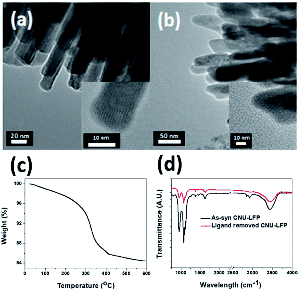 | ||
| Fig. 5 TEM images of (a) CNU-LFP, and (b) CNU-LFP annealed at 350 °C for 3 h with 4% hydrogen under argon atmosphere. (c) TGA data and (d) FT-IR of CNU-LFP. | ||
After 50 min during the second aging, urchin-shaped nanoparticles having extremely thin nanofacets appeared, as shown in Fig. 4c and d. The assembly of nanorods was facilitated during this aging, leading to the construction of intermediate urchin-shaped LiFePO4 nanoparticles.
As time elapsed, the urchin-shaped LiFePO4 nanoparticles grew gradually to form the matured nanostructure after 2 h (Fig. 4e) and the nanofacets flourished (Fig. 4f). With the elapse of aging time, the diameter of the nanoparticles and nanofacets became larger, and developed a high degree of crystallinity.
Electrochemical properties
Even if urchin-shaped nanoparticles are fabricated successfully and the cathode performance is as good as expected, the practical use of urchin-shaped nanoparticles as a cathode in LIBs still poses challenges.55–58 The surfaces of these prepared urchin-shaped nanoparticles are covered with organic polymer chains. This can be very disadvantageous for a cathode material, because the polymeric chains on the particle surfaces can trap and consume Li+ ions during the electrochemical reaction in the half cell test. It would be more desirable to remove the residual organic moieties before the electrochemical tests. Therefore, complementary experiments were performed to monitor the thermal resistance of urchin-shaped nanoparticles.To address this issue, the fully-grown urchin-shaped CNU-LFP nanoparticles were thermally treated at 350 °C for 3 h with 4% hydrogen under argon atmosphere. This temperature was considered to be sufficient for complete removal of the organic molecules from the nanoparticle surfaces. TEM imaging results shown in Fig. 5 confirmed the effective removal of organic molecules, while the nanoparticles retained their crystalline structure after the thermal treatment. To verify removal of organic ligands on the surface of the CNU-LFP after thermal treatment, we measured thermogravimetric analysis (TGA) and FT-IR (Fig. 5c and d). The weight loss was obtained between 0 and 600 °C by TGA under N2 and the rapid weight loss was observed around 350 °C. The trend of curve is similar to TGA of ethylene glycol derivatives reported previously59 and the TGA curves exhibited that calcination at 350 °C is an effective way to remove organic ligands. In Fig. 5d, the FT-IR of as-syn CNU-LFP and ligand removed CNU-LFP were exhibited. The signal at 2930 and 2953 cm−1 showed stretch vibration of alkanes of TEG. The strong bands in the C–O–C group (1074 cm−1) and primary alcohol (960 cm−1) of TEG are also included in FT-IR spectra. The signal of TEG were dramatically reduced after heat treatment and from the above data elucidate our thermal treatment is valid method to get rid of surface ligands.
To investigate electrochemical performance, the pristine and thermally annealed CNU-LFP nanoparticles were tested as an active cathode material. Coin type (CR2016) half-cell tests were performed between 2.5 to 4.0 V at a 1/20 current rate. The charge/discharge cell test result for pristine CNU-LFP are shown in Fig. 6. The specific capacity reached a value of approximately 90 mA h g−1 and faded rapidly with cycling. Considering the theoretical capacity of the LiFePO4, the decrease in capacity is significant. We assumed that the functionalized organic polymer chains on the surface of CNU-LFP nanoparticles blocked the b plane (010) of the one-dimensional Li+ ion transport pathway. As a result, this disrupts Li+ ion transport and causes Li+ ion trapping.20 This is believed to be one of the main reasons for the rapid capacity fading of pristine CNU-LFP cathodes. It can be inferred that the presence of excessive interfaces may be disadvantageous for electrochemical performance.
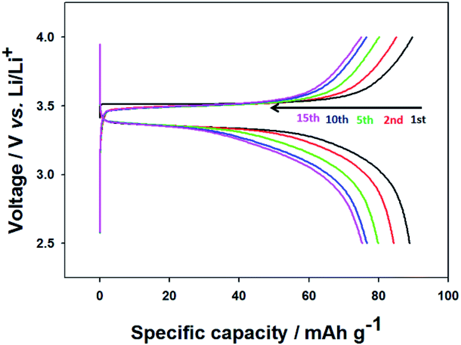 | ||
| Fig. 6 Charge/discharge curves of the CNU-LFP cathode between 2.5 and 4.0 V (vs. Li/Li+) at a current rate of 0.05C. | ||
The electrochemical test results for the thermally annealed CNU-LFP cathode are presented in Fig. 7a. The charge/discharge curves are relatively stable. It is remarkable that the initial capacity became higher than 100 mA h g−1, and the capacity faded slowly due to the removal of surface organic ligands after the annealing process, compared with pristine CNU-LFP. After the 10th cycle, the capacity reached a value of 90 mA h g−1, and the rate of capacity decrease became negligible, demonstrating the effect of thermal treatment. In addition, the electrochemical performance of the thermally annealed NU-LFP cathode was also characterized in Fig. 7b. The specific capacity of the thermally annealed NU-LFP reached a value of about 73 mA h g−1, because NU-LFP has lower surface area to volume ratio than CNU-LFP. Larger surface area to volume ratio of CNU-LFP than NU-LFP causes effective insertion and extraction of Li-ions during experiment, results in stable cycle performance (Fig. 7c and d).
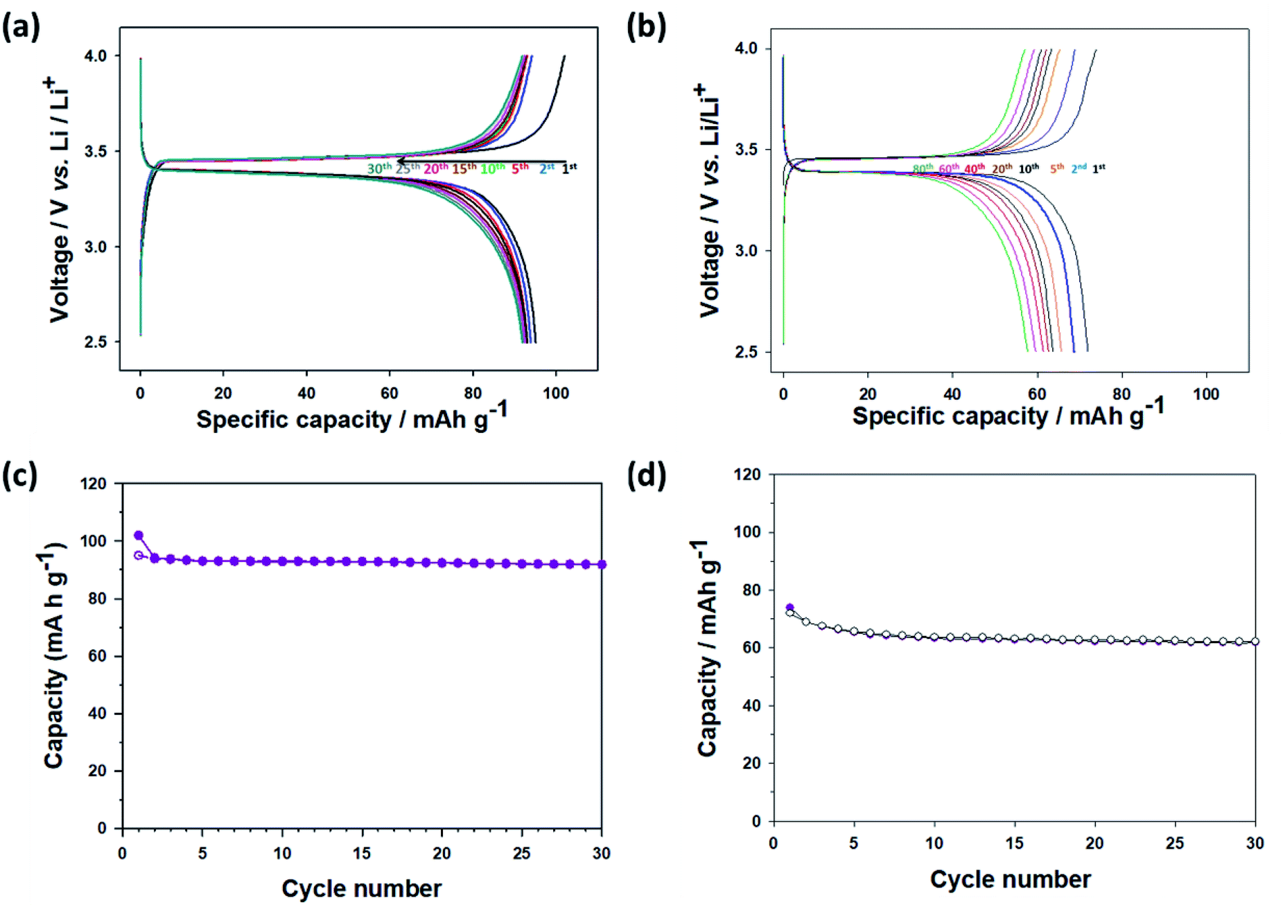 | ||
| Fig. 7 Charge/discharge curves of (a) calcinated CNU-LFP cathode and (b) calcinated NU-LFP between 2.5 and 4.0 V (vs. Li/Li+) at a current rate of 0.05C. Cyclic performance of (c) calcinated CNU-LFP cathode and (d) calcinated NU-LFP at 0.05C. | ||
Annealed CNU-LFP cathodes exhibited 101.7 mA h g−1 at the initial stage of 0.05C. Actually, the specific capacity, 101.7 mA h g−1 is lower than that of self-assembled LFP nanodendrites, 154 mA h g−1 at 0.5C.47 Although our NU-LFP have large surface area, lower density compared with micromaterials cause low volumetric energy density. The volumetric energy density of annealed CNU-LFP electrode is 521 W h L−1 (based on the volume of electrode excluding Al current collector). Although the energy density is not satisfactory, it should be noted that LFP electrodes without carbon coating was used. Further engineering such as carbon coating could lead to increase of energy density.60 Also, we also ascribe the inferior capacity to undesirable reaction from high surface area and high surface energy of NU-LFP.61 Oxidation of Fe2+ in olivine LiFePO4 is detrimental to electrochemical performances.61 Especially, the phenomenon is promoted at nano-sized materials in air atmosphere because of highly exposed surface.62 Side reaction with electrolyte is also possible factor for poor performance. We have tried to assess effect of down-sizing and hierarchical structure of nanomaterials because it is well-established that self-assembled structures of nanosized materials can decrease the transport pathways of Li+ ions and electrons.63 However, carbon coating and metal doping to micron sized materials are considered more feasible strategies to achieve high electrochemical performance. For example, carbon coated LiFePO4 nanocomposite with 158.6 mA h g−1 at 0.1C and multivalent cation doped LiFePO4 with 140.2 mA h g−1 at 5C were already reported.12,13 The Nyquist plots for calcinated CNU-LFP cathode at different cycles were shown in Fig. S1.† The large semicircles in the Nyquist plots likely indicate poor electronic contacts, which is attributed to low electronic conductivity of LFP.60,64 The Fig. 8 shows rate performance of the calcinated CNU-LFP cathode. Although the results are not impressive, we focus on electrochemical performance depending on structure of LFP and increasing electronic conductivity by carbon coating would lead to improvement.
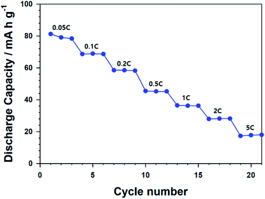 | ||
| Fig. 8 Rate performance of calcinated CNU-LFP cathode. | ||
In this study, we have focused on the structure-electrochemical performance relationship in the LiFePO4 nanostructures. An interesting LiFePO4 nanostructure was synthesized, and the accurate examination of structure–property relationships in LiFePO4 nanostructures will be an interesting research topic in the future.
Conclusions
A thermal decomposition method involving metal-surfactant complexes was developed to synthesize urchin-shaped LiFePO4 nanoparticles. The morphology of LiFePO4 nanoparticles can be tailored by the designed injection of reactants, and by the selection of surfactants. The hierarchical structure of the urchin-shaped LiFePO4 nanoparticles has brought about significant electrochemical performance improvement. As the LiFePO4 nanomaterials are still strong candidates for electrode materials in lithium ion batteries, more extensive investigations on structure–property relationships in LiFePO4 nanostructures will be a lucrative research activity.Conflicts of interest
There are no conflicts to declare.Acknowledgements
This work was supported by the National Research Foundation (NRF) grants funded by the Korean government [No. NRF-2017M3A7B6052456], and also supported by the institutional research program of Korea Institute of Science and Technology (KIST) [No. 2E28070].References
- J. Hassoun, F. Bonaccorso, M. Agostini, M. Angelucci, M. G. Betti, R. Cingolani, M. Gemmi, C. Mariani, S. Panero, V. Pellegrini and B. Scrosati, Nano Lett., 2014, 14, 4901–4906 CrossRef CAS PubMed
.
- J. E. Garbarczyk, T. K. Pietrzak, M. Wasiucionek, A. Kaleta, A. Dorau and J. L. Nowiński, Solid State Ionics, 2015, 272, 53–59 CrossRef CAS
- M. Zhao, Q. Zhao, J. Qiu, H. Xue and H. Pang, RSC Adv., 2016, 6, 95449–95468 RSC
- S.-A. Hong, D. H. Kim, K. Y. Chung, W. Chang, J. Yoo and J. Kim, J. Power Sources, 2014, 262, 219–223 CrossRef CAS
- X. Liu, J. Zeng, H. Yang, K. Zhou and D. Pan, RSC Adv., 2018, 8, 4014–4031 RSC
- Z. Weng, H. Guo, X. Liu, S. Wu, K. W. K. Yeung and P. K. Chu, RSC Adv., 2013, 3, 24758–24775 RSC
- Z.-X. Chi, W. Zhang, X.-S. Wang, F.-Q. Cheng, J.-T. Chen, A.-M. Cao and L.-J. Wan, J. Mater. Chem. A, 2014, 2, 17359–17365 RSC
- N. Böckenfeld, M. Willeke, J. Pires, M. Anouti and A. Balducci, J. Electrochem. Soc., 2013, 160, A559–A563 CrossRef
- D. Jugović and D. Uskoković, J. Power Sources, 2009, 190, 538–544 CrossRef
- C.-s. An, B. Zhang, L.-b. Tang, B. Xiao and J.-c. Zheng, Electrochim. Acta, 2018, 283, 385–392 CrossRef CAS
- J.-c. Zheng, X.-h. Li, Z.-x. Wang, H.-j. Guo and S.-y. Zhou, J. Power Sources, 2008, 184, 574–577 CrossRef CAS
- M. Chen, L.-L. Shao, H.-B. Yang, Q.-Y. Zhao and Z.-Y. Yuan, Electrochim. Acta, 2015, 168, 59–68 CrossRef CAS
- M. Chen, L.-L. Shao, H.-B. Yang, T.-Z. Ren, G. Du and Z.-Y. Yuan, Electrochim. Acta, 2015, 167, 278–286 CrossRef CAS
- R. Dominko, M. Bele, J.-M. Goupil, M. Gaberscek, D. Hanzel, I. Arcon and J. Jamnik, Chem. Mater., 2007, 19, 2960–2969 CrossRef CAS
- X.-L. Wu, L.-Y. Jiang, F.-F. Cao, Y.-G. Guo and L.-J. Wan, Adv. Mater., 2009, 21, 2710–2714 CrossRef CAS
- B. L. Ellis, W. R. M. Makahnouk, Y. Makimura, K. Toghill and L. F. Nazar, Nat. Mater., 2007, 6, 749–753 CrossRef CAS PubMed
- H. M. Xie, R. S. Wang, J. R. Ying, L. Y. Zhang, A. F. Jalbout, H. Y. Yu, G. L. Yang, X. M. Pan and Z. M. Su, Adv. Mater., 2006, 18, 2609–2613 CrossRef CAS
- H. Ghafarian-Zahmatkesh, M. Javanbakht and M. Ghaemi, J. Power Sources, 2015, 284, 339–348 CrossRef CAS
- J. Wang, Y.-c. K. Chen-Wiegart and J. Wang, Nat. Commun., 2014, 5, 4570 CrossRef CAS PubMed
- M. Farkhondeh, M. Pritzker, M. Fowler, M. Safari and C. Delacourt, Phys. Chem. Chem. Phys., 2014, 16, 22555–22565 RSC
- A. Vu and A. Stein, J. Power Sources, 2014, 245, 48–58 CrossRef CAS
- K. B. Gandrud, A. Pettersen, O. Nilsen and H. Fjellvag, J. Mater. Chem. A, 2013, 1, 9054–9059 RSC
- C. Kuss, G. Liang and S. B. Schougaard, J. Mater. Chem., 2012, 22, 24889–24893 RSC
- N. Meethong, Y.-H. Kao, S. A. Speakman and Y.-M. Chiang, Adv. Funct. Mater., 2009, 19, 1060–1070 CrossRef CAS
- S.-Y. Chung, S.-Y. Choi, T. Yamamoto and Y. Ikuhara, Angew. Chem., Int. Ed., 2009, 48, 543–546 CrossRef CAS PubMed
- J.-c. Zheng, X.-h. Li, Z.-x. Wang, S.-s. Niu, D.-r. Liu, L. Wu, L.-j. Li, J.-h. Li and H.-j. Guo, J. Power Sources, 2010, 195, 2935–2938 CrossRef CAS
- G. K. P. Dathar, D. Sheppard, K. J. Stevenson and G. Henkelman, Chem. Mater., 2011, 23, 4032–4037 CrossRef CAS
- D. Morgan, A. Van der Ven and G. Ceder, Electrochem. Solid-State Lett., 2004, 7, A30–A32 CrossRef CAS
- G. Chen, X. Song and T. J. Richardson, Electrochem. Solid-State Lett., 2006, 9, A295–A298 CrossRef CAS
- N. Böckenfeld, T. Placke, M. Winter, S. Passerini and A. Balducci, Electrochim. Acta, 2012, 76, 130–136 CrossRef
- Y. Jiang, S. Liao, Z. Liu, G. Xiao, Q. Liu and H. Song, J. Mater. Chem. A, 2013, 1, 4546–4551 RSC
- J. Mosa, M. Aparicio, A. Duran, C. Laberty-Robert and C. Sanchez, J. Mater. Chem. A, 2014, 2, 3038–3046 RSC
- M.-Y. Cho, H. Kim, H. Kim, Y. S. Lim, K.-B. Kim, J.-W. Lee, K. Kang and K. C. Roh, J. Mater. Chem. A, 2014, 2, 5922–5927 RSC
- W. Li, H. Zhang, Y. Mu, L. Liu and Y. Wang, J. Mater. Chem. A, 2015, 3, 15661–15667 RSC
- Y. Wang, Y. Wang, E. Hosono, K. Wang and H. Zhou, Angew. Chem., Int. Ed., 2008, 47, 7461–7465 CrossRef CAS PubMed
- J. Wang and X. Sun, Energy Environ. Sci., 2012, 5, 5163–5185 RSC
- S. W. Oh, S.-T. Myung, S.-M. Oh, K. H. Oh, K. Amine, B. Scrosati and Y.-K. Sun, Adv. Mater., 2010, 22, 4842–4845 CrossRef CAS PubMed
- Z. Jinli, W. Jiao, L. Yuanyuan, N. Ning, G. Junjie, Y. Feng and L. Wei, J. Mater. Chem. A, 2015, 3, 2043–2049 RSC
- D. Cintora-Juarez, C. Perez-Vicente, S. Kazim, S. Ahmad and J. L. Tirado, J. Mater. Chem. A, 2015, 3, 14254–14262 RSC
- C. Gong, F. Deng, C.-P. Tsui, Z. Xue, Y. S. Ye, C.-Y. Tang, X. Zhou and X. Xie, J. Mater. Chem. A, 2014, 2, 19315–19323 RSC
- M. Gnanavel, M. U. M. Patel, A. K. Sood and A. J. Bhattacharyya, J. Electrochem. Soc., 2012, 159, A336–A341 CrossRef CAS
- W. Shen, Y. Wang, J. Yan, H. Wu and S. Guo, Electrochim. Acta, 2015, 173, 310–315 CrossRef CAS
- Y. Huang, H. Liu, Y.-C. Lu, Y. Hou and Q. Li, J. Power Sources, 2015, 284, 236–244 CrossRef CAS
- X. Guo, Q. Fan, L. Yu, J. Liang, W. Ji, L. Peng, X. Guo, W. Ding and Y. Chen, J. Mater. Chem. A, 2013, 1, 11534–11538 RSC
- W.-B. Luo, S.-L. Chou, Y.-C. Zhai and H.-K. Liu, J. Mater. Chem. A, 2014, 2, 4927–4931 RSC
- X. Zhu, J. Hu, W. Wu, W. Zeng, H. Dai, Y. Du, Z. Liu, L. Li, H. Ji and Y. Zhu, J. Mater. Chem. A, 2014, 2, 7812–7818 RSC
- F. Teng, S. Santhanagopalan, A. Asthana, X. Geng, S.-i. Mho, R. Shahbazian-Yassar and D. D. Meng, J. Cryst. Growth, 2010, 312, 3493–3502 CrossRef CAS
- C. Sun, S. Rajasekhara, J. B. Goodenough and F. Zhou, J. Am. Chem. Soc., 2011, 133, 2132–2135 CrossRef CAS PubMed
- K. Zhang, J.-T. Lee, P. Li, B. Kang, J. H. Kim, G.-R. Yi and J. H. Park, Nano Lett., 2015, 15, 6756–6763 CrossRef CAS PubMed
- N. Meethong, H.-Y. S. Huang, W. C. Carter and Y.-M. Chiang, Electrochem. Solid-State Lett., 2007, 10, A134–A138 CrossRef CAS
- M. K. Devaraju and I. Honma, Adv. Energy Mater., 2012, 2, 284–297 CrossRef CAS
- J. Jang and J. Bae, Angew. Chem., Int. Ed., 2004, 43, 3803–3806 CrossRef CAS PubMed
- H. Kim, S.-H. Choi, M. Kim, J.-U. Park, J. Bae and J. Park, Appl. Surf. Sci., 2017, 422, 731–737 CrossRef CAS
- Z. Ma, G. Shao, Y. Fan, G. Wang, J. Song and T. Liu, ACS Appl. Mater. Interfaces, 2014, 6, 9236–9244 CrossRef CAS PubMed
- A. K. Padhi, K. S. Nanjundaswamy and J. B. Goodenough, J. Electrochem. Soc., 1997, 144, 1188–1194 CrossRef CAS
- Y. Honda, S. Muto, K. Tatsumi, H. Kondo, K. Horibuchi, T. Kobayashi and T. Sasaki, J. Power Sources, 2015, 291, 85–94 CrossRef CAS
- D. E. Demirocak and B. Bhushan, J. Colloid Interface Sci., 2014, 423, 151–157 CrossRef CAS PubMed
- Y. Wang, Z.-s. Feng, L.-l. Wang, L. Yu, J.-j. Chen, Z. Liang and R. Wang, RSC Adv., 2014, 4, 51609–51614 RSC
- F. Yang, X. Zhu, C. Li, J. Yang, J. W. Stansbury and J. Nie, RSC Adv., 2014, 4, 22224–22229 RSC
- E. Kang, Y. S. Jung, G.-H. Kim, J. Chun, U. Wiesner, A. C. Dillon, J. K. Kim and J. Lee, Adv. Funct. Mater., 2011, 21, 4349–4357 CrossRef CAS
- Y. Wang, H. Li, P. He, E. Hosono and H. Zhou, Nanoscale, 2010, 2, 1294–1305 RSC
- G. Kobayashi, S.-i. Nishimura, M.-S. Park, R. Kanno, M. Yashima, T. Ida and A. Yamada, Adv. Funct. Mater., 2009, 19, 395–403 CrossRef CAS
- C. Kim, J. W. Kim, H. Kim, D. H. Kim, C. Choi, Y. S. Jung and J. Park, Chem. Mater., 2016, 28, 8498–8503 CrossRef CAS
- M. Gaberscek, J. Moskon, B. Erjavec, R. Dominko and J. Jamnik, Electrochem. Solid-State Lett., 2008, 11, A170–A174 CrossRef CAS
Footnotes |
| † Electronic supplementary information (ESI) available. See DOI: 10.1039/c9ra00897g |
| ‡ These authors contributed equally. |
| This journal is © The Royal Society of Chemistry 2019 |