 Open Access Article
Preparation and biocompatibility of Fe50Ni50p/HAP/PEEK biocomposites with weak magnetic properties
Dengyu Liu a,
Zhenghou Zhu*a,
Jia Zhou*b,
Hui Zhaob,
Jie Chena,
Ruru Baia,
Qianying Lina and
Manikandan Alagarsamyc
aSchool of Materials Science & Engineering, Nanchang University, Nanchang 330031, China. E-mail: z00708@sina.com
bInstitute of Space Science and Technology, Nanchang University, Nanchang 330031, China. E-mail: 303248527@qq.com
cNanchang University School of Medicine, Nanchang 330031, China
First published on 29th March 2019
Abstract
Hydroxyapatite (HAP)/polyetheretherketone (PEEK) composites are widely used in the new generation of bone implant materials. The use of weak magnetic fields can promote the biocompatibility of PEEK materials. In this paper, Fe50Ni50 alloy nanopowders and Fe50Ni50/HAP/PEEK composites were prepared by liquid phase chemical reduction and liquid phase mixing. The prepared Fe50Ni50 alloy nanopowders have a particle size of about 100 nm and good chemical activity and magnetic properties. The saturation magnetization (Ms) of the Fe50Ni50 alloy powders is 70 emu g−1. Fe50Ni50 nano-powders in Fe50Ni50/HAP/PEEK composites are uniformly distributed in the matrix in the form of individual particles, achieving nano-level dispersion. With the increase of Fe50Ni50 alloy powders content, the magnetic properties of the composites are significantly enhanced. The biocompatibility of Fe50Ni50/HAP/PEEK composites is significantly better than that of PEEK and HAP/PEEK materials. The 2% Fe50Ni50/HAP/PEEK composite has the best comprehensive performance, and its biocompatibility is good. The contact angle is only 55.85°. The Ms reaches 1.5 emu g−1 and the hardness reaches 42 HBa.
1. Introduction
Bone defects are a common clinical condition. When a bone defect reaches 1.5 times the diameter of the long bone, the bone defect cannot heal and needs to be repaired.1 Artificial bone material is one of the common bone repair materials, which can effectively avoid the immune rejection caused by autologous bone or allogeneic bone transplantation.2 Polyetheretherketone (PEEK) is a rigid semi-crystalline polymer with the advantages of corrosion resistance, wear resistance, high strength, high stiffness, creep resistance and fatigue strength. Meanwhile, it will not cause tissue rejection reactions. Due to a low swelling rate and good self-lubrication, PEEK has potential to be bone implant material matrix.3 Compared with metal implants, PEEK is more compatible with bone mechanical properties,4,5 but the biological inertness of PEEK has led to its limitations.6–9 Hydroxyapatite (HAP) is one of the main inorganic components in bone.10 Shucong Yu11 dispersed different levels of HAP in PEEK and found that HAP can effectively improve the biocompatibility of PEEK. On this basis, KL Wong et al.12 prepared a HAP/PEEK composite containing niobium to enhance its biocompatibility. Wang L.13 prepared a fluorine-containing nHAP/PEEK composite with good biocompatibility and antibacterial properties in vitro.Another research hotspot for improving the biocompatibility of PEEK is the use of weak magnetic fields to promote biocompatibility.14–19 Current research shows that magnetic field can effectively promote bone growth, accelerate fracture healing, and treat bone nonunion.20–23 Yan24 studied the effect of static magnetic field (SMF) on the bone formation of rat femur by a tapered rod made of magnetized and unmagnetized samarium cobalt. The results show that the local magnetic field can locally increase the density of bone tissue. Richard Leesungbok25 found that acidified titanium-containing titanium implants can induce bone formation around the implant more quickly.
The introduction of the magnetic nanopowders into the artificial bone material not only preserves the structural role of the artificial bone in the human body, but also introduces a magnetic field to further enhance the bone repairing ability. At present, the most magnetic nanopowders used in clinical practice is Fe3O4.26 Fe3O4 is a paramagnetic material with weak magnetic properties. As a composite reinforcement, it usually needs to add more amount, which will seriously affect the mechanical properties and color of the matrix. Fe3O4 has strong oxidizing properties and is easily reduced in the human body, which affects biocompatibility.
Compared with Fe3O4, the nano FeNi alloy powders has strong magnetic properties, which can reduce the amount of addition in the composite material, and has less influence on its mechanical properties and appearance. At the same time, FeNi powders overcomes the poor magnetic properties of the elemental powders such as pure Fe powders and pure Ni powders.
In this study, nano FeNi alloy powders with better magnetic properties was used to replace Fe3O4 powders, which can reduce the amount of magnetic powders added and have less influence on the mechanical properties of the matrix.
FeNi alloy nanopowders mainly have two typical components: Fe50Ni50 and Fe20Ni80. The low cost Fe50Ni50 alloy powders was selected in this paper. At present, methods for preparing FeNi alloy nanopowders include vacuum condensation method, physical pulverization method, mechanical ball milling method, etc., but the products obtained by physical methods have low purity and uneven particle size.27 In this paper, the Fe50Ni50 alloy nanopowders was prepared by liquid phase chemical reduction method, then the Fe50Ni50 powder was compounded into HAP and PEEK powders by liquid phase blending method, and then the sample was prepared by compression molding.
2. Material and methods
2.1 Preparation of Fe50Ni50 nanopowders and Fe50Ni50/HAP/PEEK composite
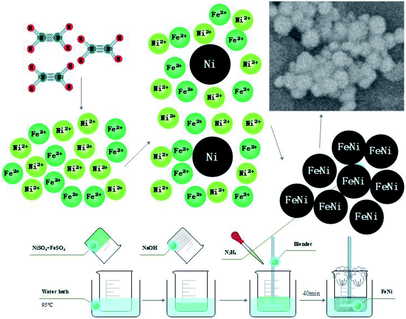
Fe50Ni50 nanopowders were prepared by liquid phase chemical reduction. A certain amount of NiSO4 (Jinchuan Group Co., Ltd, CP) and FeSO4 (Xilong Chemical Co., Ltd, AR) were dissolved in deionized water, and after thorough stirring, NaOH (Damao chemical reagent factory in Tianjin, AR) was added to form a Fe(OH)2 + Ni(OH)2 precursor. Heated to 85 °C, added N2H4 (Damao chemical reagent factory in Tianjin, AR) and stirred for 40 minutes, the color of the solution gradually grayed from green, and finally turned black, while generating a lot of irritating gas, indicating that the product of the first step was gradually reduced to Fe50Ni50 nanopowders (black precipitate). After magnetic separation and repeated extraction with absolute ethanol, a suspension of Fe50Ni50 nanopowders in absolute ethanol was obtained.28 Slowly added 20 wt% HAP (Xian Season Biotechnology Co., Ltd.), 80 wt% PEEK (Victrex® Manufacturing Ltd.) powders to the suspension, continue stirring until the powders was evenly mixed, and heated to 90 °C to remove anhydrous ethanol. Fe50Ni50/HAP/PEEK composite powders was obtained.The composite powders were heated to 375 °C in a mold and held at 15 MPa for 30 min to prepare a bulk composite sample. The sample types were PEEK, 20 wt% HAP/PEEK, 2% Fe50Ni50/20 wt% HAP/PEEK, 5% Fe50Ni50/20 wt% HAP/PEEK.
All the samples were uniformly polished with metallographic sandpaper, ultrasonically treated in an ethanol solution for 30 min, and dried at 70 °C.
2.2 Performance characterization
![[thin space (1/6-em)]](https://www.rsc.org/images/entities/char_2009.gif) :
:![[thin space (1/6-em)]](https://www.rsc.org/images/entities/char_2009.gif) 10
10![[thin space (1/6-em)]](https://www.rsc.org/images/entities/char_2009.gif) :
:![[thin space (1/6-em)]](https://www.rsc.org/images/entities/char_2009.gif) 10, and ground in an anhydrous ethanol atmosphere for two hours to prepare a slurry. The slurry was applied to a 20 mm × 10 mm nickel mesh, and the solvent was removed by drying to form an electrode. The electrochemical performance of Fe50Ni50 powders was tested by a three-electrode system using an electrochemical workstation (Shanghai Chenhua CHI760E). Among them, a platinum electrode was used as an auxiliary electrode, Hg/HgO was used as a reference electrode, and a 1 M KOH solution was used as an electrolyte. The cyclic voltammetry (CV) test has a voltage range of 0–0.75 V and a sampling interval of 0.001 V.
10, and ground in an anhydrous ethanol atmosphere for two hours to prepare a slurry. The slurry was applied to a 20 mm × 10 mm nickel mesh, and the solvent was removed by drying to form an electrode. The electrochemical performance of Fe50Ni50 powders was tested by a three-electrode system using an electrochemical workstation (Shanghai Chenhua CHI760E). Among them, a platinum electrode was used as an auxiliary electrode, Hg/HgO was used as a reference electrode, and a 1 M KOH solution was used as an electrolyte. The cyclic voltammetry (CV) test has a voltage range of 0–0.75 V and a sampling interval of 0.001 V.Analytically pure NaCl (Xilong Chemical Co., Ltd, AR, NaHCO3), KCl (Xilong Chemical Co., Ltd, AR), K2HPO4·3H2O (Xilong Chemical Co., Ltd, AR), MgCl·6H2O (Fengchuan Chemical Reagent Technology Co., Ltd, AR), HCl (Xilong Chemical Co., Ltd, AR), CaCl2 (Shanghai Yanchen Chemical Industry Co., Ltd, AR), NaSO4 (Damao chemical reagent factory in Tianjin, AR) and Tris (Sinopharm Chemical Reagent Co., Ltd) were dissolved in deionized water to buffer the solution to 7.4, and the volume was adjusted to 1 L. Simulated body fluids (SBF) were produced.29 Table 1 compares the prepared SBF solution with human blood ion concentration, and the pH range of blood plasma is 7.2–7.4. The samples were each immersed in an appropriate amount of SBF solution and the temperature was maintained at 36.5 °C. The SBF solution was changed every two days. After 7 days, the sample was taken out and washed with deionized water and then air-dried. The in vitro biocompatibility of the material was evaluated by scanning the surface topography and analyzing the surface Ca and P contents with a JSM 6701F field emission scanning electron microscope (SEM) with an energy spectrometer.
| Ion | Blood plasma (mmol−1) | SBF (mmol−1) |
|---|---|---|
| Na+ | 142.0 | 142.0 |
| K+ | 5.0 | 5.0 |
| Mg2+ | 1.5 | 1.5 |
| Ca2+ | 2.5 | 2.5 |
| Cl− | 103.0 | 147.8 |
| HCO3− | 27.0 | 4.2 |
| HPO42− | 1.0 | 1.0 |
| SO42− | 0.5 | 0.5 |
3. Results and discussion
3.1 X-ray and SEM characterization results of Fe50Ni50 powders
The powders composition of nano FeNi alloy mainly includes Fe50Ni50 and Fe20Ni80. In this paper, Fe50Ni50 alloy nanopowders were prepared by liquid phase reduction method. The reaction equation is| 2FeSO4 + N2H4 + 4NaOH → 2Fe↓ + N2↑ + 4H2O + 2Na2SO4 | (1) |
| 2NiSO4 + N2H4 + 4NaOH → 2Ni↓ + N2↑ + 4H2O + 2Na2SO4 | (2) |
Due to difference of Gibbs free energy value (G value) in the reduction reaction of Fe2+ and Ni2+, the preparation of alloy nanopowders must be completed by a two-step process by adjusting the reaction rate and the concentration of the reactant. First, the reaction rate and the Fe2+/Ni2+ concentration ratio was adjusted, and the Ni nucleus was formed. Then, the reduction reaction was synchronized by adjusting the reaction rate. Fe2+ and Ni2+ were simultaneously deposited on the crystal nucleus to form an alloy after reduction. The schematic diagram of the reaction principle is shown in Fig. 1.
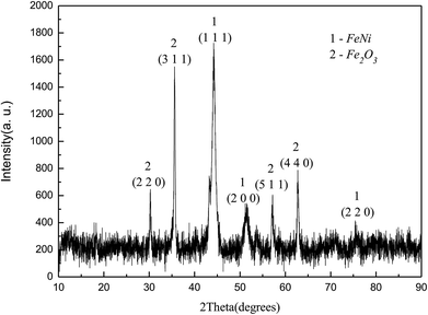
Fig. 2 showed the XRD diagram of Fe50Ni50 powders obtained by liquid phase chemical reduction, in which 1 was the corresponding peak of Fe50Ni50 and 2 was the corresponding peak of Fe2O3. Due to the excess Fe2+ in the reactant, Fe atom cladding layer was mainly formed in the later stage of the reaction. With low G value of Fe2O3, Fe atom on the surface layer was oxidized to form Fe2O3 in the air. Fig. 3 was a SEM photograph of a Fe50Ni50 powders, in which the particle diameter was about 100 nm, reaching the nanometer scale and having a high surface energy.
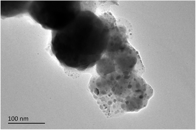
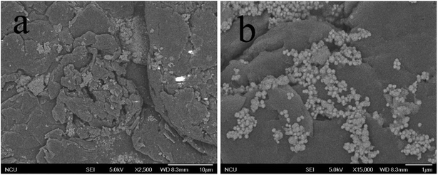
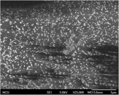
Fig. 4 and 5 were SEM images of composite powders and composites respectively. The nanoscale Fe50Ni50 powders in the composite powders were dispersed in the surface cracks of HAP powders with large particle size, forming a stable complex. After the composite powders was pressed at high temperature, the Fe50Ni50 powders flowed with the PEEK matrix and redistributes to become the composite material. In the composite materials, the Fe50Ni50 nanometer powders were uniformly distributed in the matrix in the form of a single particle, reaching the nano-scale dispersion level.
3.2 Electrochemical activity of Fe50Ni50 powders
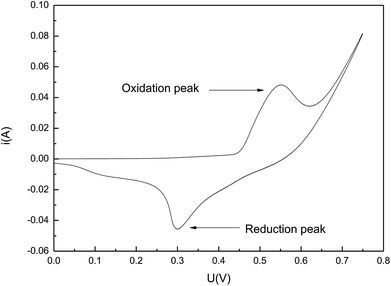
The high chemical activity of Fe50Ni50 powders was beneficial to improve the biocompatibility of the composite. Through repeated experiments, the scanning speed was chosen to be 0.1 V s−1. It could be seen from Fig. 6 that the CV curve has obvious and symmetric oxidation peaks and reduction peaks, indicating that the electrodes have a certain reversibility. At the high scanning speed of 0.1 V s−1, there were still obvious oxidation peaks and reduction peaks, and the peak current of the oxidation peak reached 0.0457 A, indicating that the electrochemical activity of Fe50Ni50 is very high.3.3 Contact angle studies
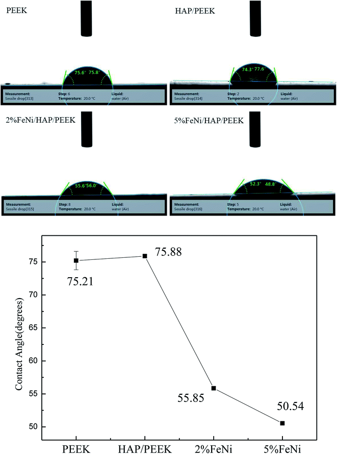
The contact angle of the biocomposite can reflect the wetting properties of the material,30–33 while the wetting performance is directly related to the wear of the material surface. The results of contact angle studies are shown in Fig. 7. The four materials are all hydrophilic materials. The contact angles of PEEK and HAP/PEEK are 75.21° and 75.88°, respectively. After adding 2% and 5% FeNi powder, the contact angle of the composite is reduced to 55.85° and 50.54°, respectively. According to Fig. 6, FeNi powder has good electrochemical properties and surface energy. FeNi enables the surface of biological composites to have a higher surface free energy, which increases the surface tension difference with the liquid, thus improving the material's wettability and reducing wear.3.4 Biocompatibility evaluation
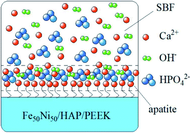
In Fig. 8a–d were SEM images of PEEK, HAP/PEEK, 2% Fe50Ni50/HAP/PEEK, and 5% Fe50Ni50/HAP/PEEK samples immersed in SBF solution for 7 days. After SBF solution immersion, no significant changes in the surface of PEEK. P and Ca elements are also not found in Fig. 9a, with only a few impurities reflecting the biological inertness of the PEEK material. The surface of HAP/PEEK was formed with micron crystal shape, and it was found that these crystals are separated from each other by high magnification and did not form into continuous sheets. The composition of these crystals was determined to be apatite by combining the P and Ca ratios in Fig. 9 energy spectrometer. Continuous layer structure with certain thickness was formed on the surface of 2% Fe50Ni50/HAP/PEEK and 5% Fe50Ni50/HAP/PEEK samples. Meanwhile, granular Fe50Ni50 powder particles and rod-like apatite could be clearly seen on both samples. Among them, the crystal particle size on the surface of 5% Fe50Ni50/HAP/PEEK samples was the largest. With the introduction of the HAP, the PEEK surface contains a large number of Ca2+, which can induce a nuclear growth of the phosphorite crystals. As a result of electrostatic action, HPO42−, OH− and Ca2+ in SBF solution will continuously accumulate on the material surface to form apatite crystals.34 Fig. 10 shows the physical model of apatite formation on the composite surface. The introduction of HAP can improve the biocompatibility of PEEK.10 FeNi powder will not interfere with the production of apatite crystals on PEEK surface, but will also increase the electrochemical activity of the materials and promote the formation of crystallization process.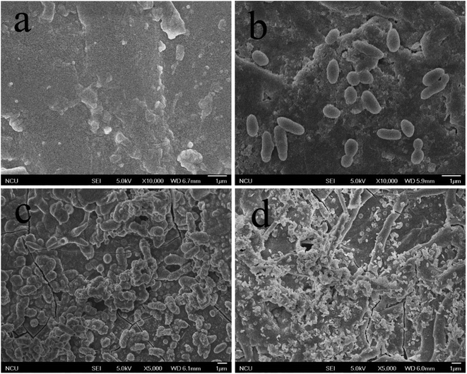 | ||
| Fig. 8 SEM images of the surface of (a) PEEK, (b) HAP/PEEK composite, (c) 2% Fe50Ni50/HA/PEEK composite and (d) 5% Fe50Ni50/HA/PEEK composite after 7 days of immersion in SBF solution. | ||
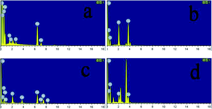 | ||
| Fig. 9 Energy spectrum diagram of (a) PEEK, (b) HAP/PEEK composite, (c) 2% Fe50Ni50/HAP/PEEK composite and (d) 5% Fe50Ni50/HAP/PEEK composite after 7 days of immersion in SBF solution. | ||
3.5 Mechanical performance evaluation
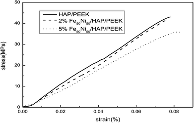
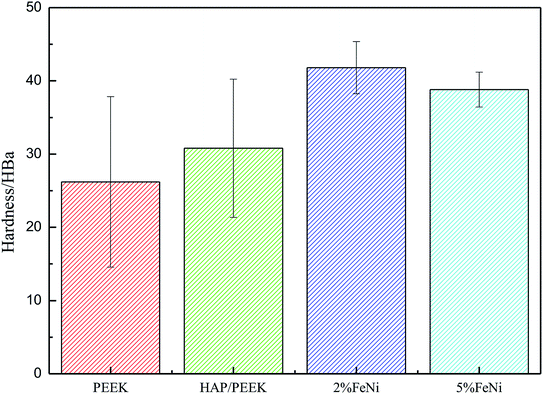
Fig. 11 reflected the tensile properties of the composite after the Fe50Ni50 powders was composited into HAP/PEEK. Due to the HAP powders composite material in PEEK, the elongation of HAP/PEEK material decreased greatly and the material was brittle. In Fig. 11, the tensile curve of HAP/PEEK material was linear under slight strain, the material was in elastic deformation stage, the material fracture was brittle fracture, and the breaking strength was 43.02 MPa. After compounding Fe50Ni50 powders in HAP/PEEK material, the elongation of the composite material was improved due to the pinning effect of the powders on microcracks. However, due to the small particle size of Fe50Ni50 nanopowders, its microcracking effect was small. When the powders content was small, the tensile curve of the composite was not significant. Fig. 11 showed that when the Fe50Ni50 nanopowders content was 2%, the effect of the powders on the overall tensile curve of the composite was not significant. When the content of Fe50Ni50 nanopowders was 5%, the elongation of the composite was significantly improved. When the elongation was 0.08%, the stress values of HAP/PEEK, 2% Fe50Ni50/HAP/PEEK and 5% Fe50Ni50/HAP/PEEK were 43.02 MPa, 41.85 MPa and 35.89 MPa, respectively.For bone implant materials, it is desirable that the material has a certain hardness to protect the artificial bone from being easily damaged when subjected to physical external forces. Fig. 12 reflected the change in hardness properties of composites after Fe50Ni50 powders was compounded into HAP/PEEK. Compared with the tensile properties, the Fe50Ni50 powders had a significant effect on the hardness of the composite. The hardness of HAP/PEEK, 2% Fe50Ni50/HAP/PEEK and 5% Fe50Ni50/HAP/PEEK were 30.8 HBa, 41.8 HBa and 38.8 HBa, respectively.
3.6 Magnetic performance characterization
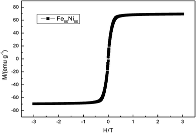
Fig. 13 was a hysteresis loop of the nano Fe50Ni50 soft magnetic alloy powders prepared at room temperature. The abscissa was the applied magnetic field strength and the ordinate was the magnetization. Fig. 14 was the hysteresis loop of nano Fe3O4 powders prepared by Yan Wei at room temperature.35 Among them, the saturation magnetizations of the four powders a, b, c, and d were 50.61, 61.36, 56.05, 55.43 emu g−1, respectively. As can be seen from Fig. 13, the Ms of the Fe50Ni50 powders was 70 emu g−1, which was significantly higher than that of the Fe3O4 powders. The hysteresis loop of the Fe50Ni50 powders with better magnetic properties added to the HAP/PEEK composite was shown in Fig. 15. The magnetic properties of the composite material with 5% content were better than those of the composite material with 2% content. According to the percolation theory studied by Ruru Bai, the magnetically permeable powders formed a pathway as shown in Fig. 16 in the matrix. With the increase of the content of magnetically permeable powders, the composite material would experience the non-magnetic permeability zone, the magnetic permeability seepage zone and the magnetic permeability saturation zone.36 The composite magnetic powders prepared in this paper had a small amount of magnetic powders, and the spacing between the powders was large, and it was difficult to form a passage between the powders, so the magnetic permeability was still small. However, the Ms of 2% Fe50Ni50/HAP/PEEK and 5% Fe50Ni50/HAP/PEEK materials reached 1.5 emu g−1 and 3 emu g−1, respectively, with weak magnetic properties.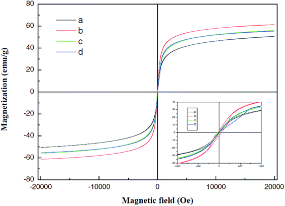 | ||
| Fig. 14 Room temperature hysteresis loop of Fe3O4.35 | ||
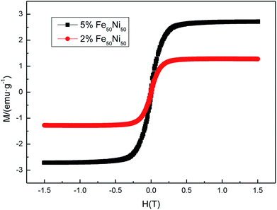 | ||
| Fig. 15 Room temperature hysteresis loop of HAP/PEEK composite with 2% Fe50Ni50 powders and 5% Fe50Ni50 powders. | ||
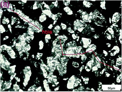 | ||
| Fig. 16 Magnetically permeable powders forms a pathway in the resin matrix.18 | ||
4. Conclusion
Fe50Ni50 alloy nanopowders and Fe50Ni50/HAP/PEEK composites were prepared by liquid phase chemical reduction method and liquid phase mixing method. The prepared Fe50Ni50 alloy nanopowders had a particle size of about 100 nm and had good chemical activity and magnetic properties. The Ms of Fe50Ni50 alloy powders was 70 emu g−1, which was significantly higher than that of Fe3O4 powders. Fe50Ni50 nanopowders in Fe50Ni50/HAP/PEEK composites were uniformly distributed in the matrix in the form of individual particles, achieving nano-level dispersion. With the increase of Fe50Ni50 alloy powders content, the magnetic properties of the composites are significantly enhanced. The Ms of 2% Fe50Ni50/HAP/PEEK and 5% Fe50Ni50/HAP/PEEK materials reached 1.5 emu g−1 and 3 emu g−1, respectively, with weak magnetic properties.The biocompatibility of Fe50Ni50/HAP/PEEK composites was significantly better than that of PEEK and HAP/PEEK materials. The elongation and hardness of composites were improved due to the pinning and dispersion strengthening effects of Fe50Ni50 powders on microcracks. The 2% Fe50Ni50/HAP/PEEK composite had the best comprehensive performance, and its biocompatibility was good. The contact angle was only 55.85°. The Ms reached 1.5 emu g−1 and the hardness reached 42 HBa.
Conflicts of interest
There are no conflicts to declare.References
- J. P. Schmitz and J. O. Hollinger, Clin. Orthop. Relat. Res., 1986, 299–308 CAS.
- T. W. Bauer and G. F. Muschler, Clin. Orthop. Relat. Res., 2000, 10–27 CrossRef CAS.
- S. M. Kurtz and J. N. Devine, Biomaterials, 2007, 28, 4845–4869 CrossRef CAS PubMed.
- D. J. Jaekel, D. W. MacDonald and S. M. Kurtz, J. Mech. Behav. Biomed. Mater., 2011, 4, 1275–1282 CrossRef CAS PubMed.
- M. F. Arif, S. Kumar, K. M. Varadarajan and W. J. Cantwell, Mater. Des., 2018, 146, 249–259 CrossRef CAS.
- C. H. Rivard, S. Rhalmi and C. Coillard, J. Biomed. Mater. Res., 2002, 62, 488–498 CrossRef CAS PubMed.
- N. Sheiko, P. Kekicheff, P. Marie, M. Schmutz, L. Jacomine and F. Perrin-Schmitt, Appl. Surf. Sci., 2016, 389, 651–665 CrossRef CAS.
- N. J. Hallab, Q. B. Bao and T. Brown, Eur. Spine J., 2013, 22, 2740–2751 CrossRef PubMed.
- K. B. Sagomonyants, M. L. Jarman-Smith, J. N. Devine, M. S. Aronow and G. A. Gronowicz, Biomaterials, 2008, 29, 1563–1572 CrossRef CAS PubMed.
- H. Zhou and J. Lee, Acta Biomater., 2011, 7, 2769–2781 CrossRef CAS PubMed.
- S. C. Yu, K. P. Hariram, R. Kumar, P. Cheang and K. K. Aik, Biomaterials, 2005, 26, 2343–2352 CrossRef CAS PubMed.
- K. L. Wong, C. T. Wong, W. C. Liu, H. B. Pan, M. K. Fong, W. M. Lam, W. L. Cheung, W. M. Tang, K. Y. Chiu, K. D. K. Luk and W. W. Lu, Biomaterials, 2009, 30, 3810–3817 CrossRef CAS PubMed.
- L. X. Wang, S. He, X. M. Wu, S. S. Liang, Z. L. Mu, J. Wei, F. Deng, Y. Deng and S. C. Wei, Biomaterials, 2014, 35, 6758–6775 CrossRef CAS PubMed.
- S. Guba, B. Horvath and I. Szalai, J. Magn. Magn. Mater., 2017, 444, 173–177 CrossRef CAS.
- F. Crippa, T. L. Moore, M. Mortato, C. Geers, L. Haeni, A. M. Hirt, B. Rothen-Rutishauser and A. Petri-Fink, J. Magn. Magn. Mater., 2017, 427, 212–219 CrossRef CAS.
- D. E. Igartua, P. L. Azcona, C. S. Martinez, S. D. V. Alonso, V. L. Lassalle and M. J. Prieto, Toxicol. Appl. Pharmacol., 2018, 358, 23–34 CrossRef CAS PubMed.
- J. H. Huang, W. Liu, Y. J. Liang, L. Li, L. Duan, J. L. Chen, F. Y. Zhu, Y. X. Lai, W. M. Zhu, W. You, Z. F. Jia, J. Y. Xiong and D. P. Wang, Mater. Sci. Eng., C, 2018, 87, 70–77 CrossRef CAS PubMed.
- P. Bury, J. Kudelcik, S. Hardon, M. Kubovcikova, M. Timko and P. Kopcansky, Phys. Procedia, 2015, 75, 1029–1034 CrossRef CAS.
- A. Sunny, K. S. A. Kumar, V. Karunakaran, M. Aathira, G. R. Mutta, K. K. Maiti, V. R. Reddy and M. Vasundhara, Nano-Struct. Nano-Objects, 2018, 16, 69–76 CrossRef CAS.
- S. Yamaguchi-Sekino, T. Kira, M. Sekino and M. Akahane, Bioelectromagnetics, 2019, 40, 16–26 CrossRef CAS PubMed.
- Y. Xia, J. Sun, L. Zhao, F. Zhang, X. J. Liang, Y. Guo, M. D. Weir, M. A. Reynolds, N. Gu and H. H. K. Xu, Biomaterials, 2018, 183, 151–170 CrossRef CAS PubMed.
- T. Calcagnotto, M. M. B. Schwengber, C. C. De Antoni, D. L. de Oliveira, T. M. Vago and J. Guilinelli, Ann. Maxillofac. Surg., 2017, 7, 18–24 Search PubMed.
- J. Zhang, C. Ding, L. Ren, Y. Zhou and P. Shang, Prog. Biophys. Mol. Biol., 2014, 114, 146–152 CrossRef PubMed.
- Q. C. Yan, N. Tomita and Y. Ikada, Med. Eng. Phys, 1998, 20, 397–402 CrossRef CAS PubMed.
- R. Leesungbok, S. J. Ahn, S. W. Lee, G. H. Park, J. S. Kang and J. J. Choi, J. Oral Implantol., 2013, 39, 248–255 CrossRef.
- A. Ali, H. Zafar, M. Zia, I. Ul Haq, A. R. Phull, J. S. Ali and A. Hussain, Nanotechnol., Sci. Appl., 2016, 9, 49–67 CrossRef CAS PubMed.
- V. L. Kurichenko, D. Y. Karpenkov, A. Y. Karpenkov, M. B. Lyakhova and V. V. Khovaylo, J. Magn. Magn. Mater., 2019, 470, 33–37 CrossRef CAS.
- Z. H. Zhu, H. Zhao and H. Song, Mater. Chem. Phys., 2016, 172, 173–178 CrossRef CAS.
- T. Kokubo and H. Takadama, Biomaterials, 2006, 27, 2907–2915 CrossRef CAS PubMed.
- B. Yang, S. Q. Zhang, S. S. Li, H. F. Yao, W. N. Li and J. H. Hou, Adv. Mater., 2019, 31, 1804657 CrossRef PubMed.
- D. P. Suhas, T. M. Aminabhavi and A. V. Raghu, Appl. Clay Sci., 2014, 101, 419–429 CrossRef CAS.
- D. P. Suhas, T. M. Aminabhavi and A. V. Raghu, Polym. Eng. Sci., 2014, 54, 1774–1782 CrossRef CAS.
- D. P. Suhas, T. M. Aminabhavi, H. M. Jeong and A. V. Raghu, RSC Adv., 2015, 5, 100984–100995 RSC.
- D. N. Mohd, A. A. R. Hussein, K. M. R. Abdul and S. Syafiqah, Ann. Anat., 2018, 220, 29–37 CrossRef PubMed.
- Y. Wei, B. Han, X. Y. Hu, Y. H. Lin, X. Z. Wang and X. L. Deng, Procedia Eng., 2012, 27, 632–637 CrossRef CAS.
- R. R. Bai, Z. H. Zhu, H. Zhao, S. H. Mao and Q. Zhong, J. Magn. Magn. Mater., 2017, 433, 285–291 CrossRef CAS.
| This journal is © The Royal Society of Chemistry 2019 |

