 Open Access Article
Expanded graphite/NiAl layered double hydroxide nanowires for ultra-sensitive, ultra-low detection limits and selective NOx gas detection at room temperature†
Xueying Zhanga,
Muhammad Ikrama,
Zhi Liua,
Lei Tenga,
Jialing Xuea,
Di Wanga,
Li Li*ab and
Keying Shi *ac
*ac
aKey Laboratory of Functional Inorganic Material Chemistry, Ministry of Education, School of Chemistry and Material Science, Heilongjiang University, Harbin 150080, PR China. E-mail: shikeying2008@163.com; lili1993036@hlju.edu.cn
bKey Laboratory of Chemical Engineering Process & Technology for High-efficiency Conversion, School of Chemistry and Material Science, Heilongjiang University, Harbin 150080, PR China
cKey Laboratory for Photonic and Electronic, Ministry of Education, Modern Experiment Center, Harbin Normal University, Harbin 150025, PR China
First published on 18th March 2019
Abstract
To develop an ultra-sensitive and selective NOx gas sensor with an ultra-low detection limit, expanded graphite/NiAl layered double hydroxide (EG/NA) nanowires were synthesized by using hydrothermal method with EG as a template and adjusting the amount of urea in the reaction. X-ray diffraction and transmission electron microscopy showed EG/NA3 nanowires with a diameter of 5–10 nm and a length greater than 100 nm uniformly dispersed on the expanded graphite nanosheet (>8 layers). The synergy between NiAl layered double hydroxide (NiAl-LDH) and expanded graphite (EG) improved the gas sensing properties of the composites. As expected, gas sensing tests showed that EG/NA composites have superior performance over pristine NiAl-LDH. In particular, the EG/NA3 nanowire material exhibited an ultra-high response (Ra/Rg = 17.65) with ultra-fast response time (about 2 s) to 100 ppm NOx, an ultra-low detection limit (10 ppb) and good selectivity at room temperature (RT, 24 ± 2 °C), which could meet a variety of application needs. Furthermore, the enhancement of the sensing response was attributed to the nanowire structure formed by NiAl-LDH in the EG interlayer and the conductive nanonetwork of interwoven nanowires.
Introduction
Nitrogen oxides (expressed as NOx, including NO and NO2), volatile and pungent, are toxic gases that can be fatal to humans. Recently, the high amount of NOx emissions from diesel vehicles has become an increasingly serious problem.1 Furthermore, NOx is an important factor in the atmosphere, affecting formation of photochemical smog and O3 consumption.2 Therefore, there is an urgent need to develop ambient-operational and low-cost NOx sensors with ultra-sensitive, ultra-fast, ultra-low detection limits and good selectivity at RT.In the past few decades, sensors using electronic signals for NOx gas detection based on various materials, such as metal oxides,3 polymers,4 MoS25 and carbon materials,6,7 have been reported. In particular, due to their excellent physical and electrical properties, carbon materials, such as carbon nanotubes (CNTs), carbon black (CB), graphene (GN), and carbon nitride (g-C3N4) nanomaterials, have received great attention as gas sensor materials.8 Seekaew et al.9 obtained 3D TiO2/graphene–carbon nanotube (TiO2/G-CNT) composites by chemical vapor deposition and sparking. It was found that 3D TiO2/G-CNT composites with optimum spark time of 60 s at RT showed high response to toluene (500 ppm, ∼42%). Chu et al.10 synthesized three-dimensional (3D) α-Ni(OH)2/carbon black composites (NiCB) by a simple reflux method. It was found that NiCB composites with 20 mg carbon black had excellent response to NO2 gas at RT (100 ppm, ∼62.45%). Ye et al.11 obtained graphene nanoplate (GN)-polyaniline (PANI) composites through in situ polymerization, which exhibited good sensor response for 100 ppm NH3 at RT (15 ppm, ∼1.5%). Gong et al.12 successfully synthesized a g-C3N4 modified ball-flower like Co3O4 composite (Co3O4/pCNH) by a simple hydrothermal method. It was found that the Co3O4/pCNH composites exhibited a very high response to ethanol gas at 210 °C (500 ppm, ∼30.2%). However, due to the high curvature of 0D carbon spheres and 1D CNTs, nanomaterials are not easily grown on their surfaces. EG and g-C3N4 are ideal atomic thickness 2D substrates for anchoring nanomaterials.12,13 In our previous work, EG was used as a substrate to synthesize CeO2/graphene nanoflower composites. The sensitivity of CeO2/graphene composites for 100 ppm NOx was 10.39% at RT.14 However, due to its sluggish response, it is not well suited for commercial application.
Among the most promising materials, LDH materials have been widely used for catalysts,15 anion exchange,16 magnetic elements17 and oxide precursors, owing to their versatility in both chemical composition and structural morphology.18–20 Recently, LDHs have received great attention as gas sensitive materials due to their high specific surface area and short carrier transport diffusion length.21–23 However, application of pristine LDHs has been hindered due to their low electrical conductivity and tendency to stack easily in the solid state.24
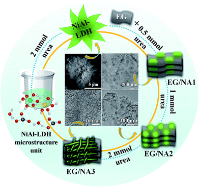
To overcome these problems, in the present work, EG and LDHs were combined to synthesize a nanomaterial with the advantages of enhanced gas sensitivity, ultra-low detection limit, and improved response and response time, all of which were beneficial for practical and commercial application of composite materials.25 The EG/NiAl-LDH composites were synthesized by using EG and varying the amount of urea in the hydrothermal reaction. The entire process is illustrated in Scheme 1. The process begins with activated EG and then synthesizes EG/NA nanowires by vacuum impregnation and hydrothermal methods. During vacuum impregnation, the EG interlayer was opened and the NiAl-LDH precursor solution was pumped into the interlayers of EG. Subsequently, EG was used in the hydrothermal process for (i) its functional surface, which served as a template for NiAl-LDH nucleation and provided anchor sites for LDH nanosheets; (ii) its conductivity in EG/NA composites.26 At the same time, by using EG and changing the concentration of urea in the precursor solution, the morphology of the obtained NiAl hydrotalcite was tuned from a three-dimensional (3D) flower structure to EG-loaded NiAl-LDH nanosheets, especially EG/NA nanowires. It is worth noting that EG/NA nanowires exhibited superior performance for NOx gas compared to other forms of NiAl-LDH materials such as nanosheets and nanoparticles.
Experimental
Materials
All chemicals in this work were of analytic grade and were used without further purification. Nickel nitrate, aluminum nitrate, sodium dodecyl sulfate (SDS) and urea were purchased from Sinopharm Chemical Reagent Co., Ltd. Expandable graphite (300 mesh) was purchased from Qingdao Tianyuan Company.Synthesis of EG/NA nanowires
The EG/NA composite was synthesized by microwave heating-vacuum assisted-hydrothermal method. Specifically, 0.2 mmol Ni(NO3)2·6H2O, 0.1 mmol Al(NO3)3·9H2O, 0.15 mmol SDS and different amounts of urea (0.5, 1.0, 2.0 and 3.0 mmol) were dissolved in 40 mL distilled water and the mixed solution was continuously stirred for 30 min, resulting in NiAl-LDH precursor solution. The desired multilayer EG structure was obtained by heating expandable graphite using the intermittent microwave heating (IMH) method. The prepared EG (40 mg) was spread on the bottom of a suction bottle, which was sealed with a dropping funnel containing NiAl-LDH precursor solution. After the suction bottle was kept under vacuum for 30 min, the NiAl-LDH precursor solution was added dropwise and the vacuum environment facilitated its complete injection into the graphite layer. After the addition was complete, the mixture was stirred for 30 min and transferred to a 50 mL Teflon-lined stainless steel autoclave for hydrothermal reaction at 150 °C for 6 h to obtain the product. After cooling to RT, the product was washed several times (water + ethanol) and dried at 80 °C for 10 h to obtain EG/NA composites in air. The EG/NA samples with various loadings of urea were named EG/NA1, EG/NA2, EG/NA3, and EG/NA4, by increasing concentrations of urea. For comparison, pure NiAl-LDH was also prepared: 0.2 mmol Ni(NO3)2·6H2O, 0.1 mmol Al(NO3)3·9H2O, 0.15 mmol SDS and 2 mmol urea were dissolved in 40 mL distilled water in the absence of EG, then the same synthesis conditions and processes described above were applied.Material characterization
The crystalline structures of composites were recorded with X-ray powder diffraction (XRD, D/max-IIIB-40 kV, Japan, Cu Kα radiation, λ = 1.5406 Å) and infrared spectra (IR, Perkin Elmer Spectrometer, KBr pellet technique). Raman spectroscopy was performed on a Renishaw in Via-Reflex confocal Raman microscope using an excitation wavelength of 532 nm. The morphologies and structures of composites were examined using transmission electron microscopy (TEM, JEOL 2100) at 200 kV. Brunauer–Emmett–Teller (BET) surface area and pore size distribution were determined using a Quantachrome Autosorb-1 C-VP unit. XPS spectra were recorded with a VGESCALAB MK II using Mg Kα (1253.6 eV) achromatic X-ray radiation. Mott–Schottky plot measurements (MS) and electrochemical impedance spectroscopy (EIS) were carried out using a CHI600E electrochemical work station in a half-cell setup configuration at RT.Preparation of film sensors
A certain amount of the sample was placed in 0.1 mL ethanol and sonicated for a few minutes to obtain a suspension. 0.05 mL of the suspension was dropped on a crossed Au electrode (7 mm × 5 mm × 0.38 mm) by hanging drop method, followed by drying at 80 °C for 4 h to obtain a film sensor. Each Au electrode contains 100 fingers, with a distance of 20 mm between the two fingers.Gas sensing measurements
The gas sensing process of the thin film sensor is shown in Fig. S1.† In this experiment, four sensors were used for each sample set to investigate the reproducibility of the thin film sensor. The sensor was connected to a glass test chamber having a volume of 1000 mL (the test chamber included an inlet and an outlet). The chamber was then flushed with air for a few minutes to remove contaminants from the test chamber and stabilize the film before testing. A desired volume of target gas was injected into the chamber using a microsyringe. The sensor was probed with a constant voltage of 5 V and the changes in resistance and exposure time were analyzed while monitoring the current through the film at RT. The gas response was defined as: R = Ra/Rg, where Ra and Rg represent the sensor resistances in fresh air and target gas, respectively. The response time was defined as the time required for the sensor to reach 80% of the total resistance change when the manufactured sensor was exposed to the target gas and air. Test conditions: RT (24 ± 2 °C); relative humidity (RH, 24 ± 4%).Results and discussion
Morphology and structure characterizations
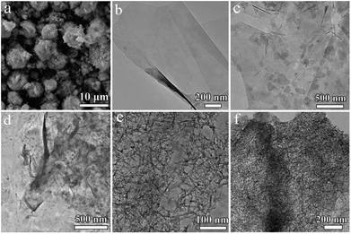
The morphologies of the synthesized NiAl-LDH in different conditions are shown in SEM and TEM. Fig. 1a shows the 3D flower structure of NiAl-LDH synthesized in 2 mmol urea in the absence of EG. Fig. 1b is a TEM image of pure EG, from which it can be seen that EG presented a thin plate structure. Fig. 1c shows a TEM image of EG/NA1, synthesized in the presence of EG and urea (0.5 mmol), obtaining EG-loaded NiAl-LDH nanosheets. It was observed that the NiAl-LDH nanosheets were evenly dispersed on the surface of the EG plate and most were parallel to the EG plate. It is worth mentioning that the addition of EG in the hydrothermal reaction significantly changed the assembled structure of NiAl-LDH, from 3D flower structure to nanosheet. This was attributed to the polar surfaces of the EG and NiAl-LDH plates and the electrostatic interaction between EG and NiAl-LDH.When urea loading increased to 1 mmol, there was a large number of particles and a small amount of nanowire attached to the EG surface (EG/NA2, Fig. 1d). When urea loading was further increased to 2 mmol and 3 mmol, the morphology of nanowires became well developed (EG/NA3 and EG/NA4, Fig. 1e and f). By comparing the morphologies of pristine NiAl-LDH and EG-loaded NiAl-LDH, it could be concluded that EG played an important role in synthesising EG/NA nanowires: the electrostatic interaction between the EG plate and NiAl-LDH nanosheets prevented aggregation of the obtained NiAl-LDH.27 In summary, TEM results showed that the addition of EG and the change of urea loading in the hydrothermal reaction changed the morphology of NiAl-LDH.
X-ray diffraction (XRD) measurements were taken to confirm the phases and structures of the composite materials. Fig. 2a showed that the EG/NA composites had an XRD pattern similar to NiAl-LDH. The peak at 26.5° was attributed to the (002) plane of the hexagonal graphite structure; the lower strong diffraction peaks at 11.7°, 35.2°, 38.4° and 61.1° correspond to the (003), (012), (104) and (110) atomic surface reflections, respectively, of the LDH phase (JCPDS card no. 15-0087). This indicated that the presence of EG did not affect the crystal structure of the synthesized NiAl-LDH. However, compared to the Bragg reflection intensity of NiAl-LDH, EG/NA1 exhibited weaker (003), (006) and (009) Bragg reactions, indicating there was less ordered stacking of LDH nanosheets. This might be attributed to the polar surface of the EG plate interfering with the orderly stacking of LDH nanosheets by electrostatic interaction.28,29 As the amount of urea increased, the peak intensity of EG/NA2 further weakened, indicating the ordered stacking of LDH nanosheets was further reduced, and nanoparticles began to appear. EG/NA3 and EG/NA4 nanowires presented nearly identical XRD patterns, indicating that they had nearly identical nanowire compositions.
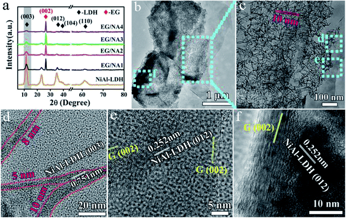 | ||
| Fig. 2 (a) XRD patterns of NiAl-LDH and EG/NA composites; (b and c) TEM images of the EG/NA3 nanowires; (d–f) HRTEM images of the EG/NA3 nanowires. | ||
To further investigate the morphology and structure of the EG/NA3 nanowires, TEM/HRTEM were carried out (Fig. 2b–f). Fig. 2b shows that a large number of nanowires were grown on the EG plate; the EG/NA3 nanowires with large specific surface area had a diameter of 5–10 nm and length greater than 100 nm, as shown in Fig. 2c and d. The large specific surface area was confirmed by the N2 adsorption/desorption isotherms (Fig. 3). The specific surface area (107.3 m2 g−1) of EG/NA3 was 2.4 times that of NiAl-LDH (45.4 m2 g−1). The nanowires with large specific surface area shorten the diffusion distance of carriers, which facilitates efficient and rapid delivery of gases to active sites for quick adsorption and desorption.30,31 This network of ultra-thin nanowires also ensured a maximum exposure of active metal ions to gas.32 In addition, the interlayer of multi-layer expanded graphite could accommodate large volume changes of nanowires, avoiding collapse or deformation during repeated adsorption and desorption.33 HRTEM images of EG/NA3 displayed in Fig. 2d–f indicate that the nanowires were formed by nano-sized crystals and the lattice spacings 0.751 and 0.252 nm correspond to the (003) and (012) planes of the NiAl-LDH nanocrystal, respectively; 0.21 nm corresponds to the (002) plane of EG. These results were in good agreement with XRD results.
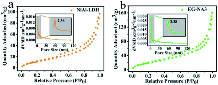 | ||
| Fig. 3 N2 adsorption–desorption isotherms of nanocomposites (inset is the pore diameter distribution curve of the corresponding sample): (a) NiAl-LDH; (b) EG/NA3. | ||
The FT-IR and Raman spectra of the prepared samples are shown in Fig. 4. In Fig. 4a, EG/NA3 had similar infrared characteristic peaks as NiAl-LDH. The broad band in the range of 3000–3500 cm−1 corresponds to the stretching mode of O–H from the brucite-like layer and interlayer water molecules.34 The interlayer H2O could also be observed close to 1600 cm−1.35 The strong vibration band near 1379 cm−1 was attributed to interlayer carbonate36,37 and M–O–C (M: metal atom) was recorded at 1065 cm−1.38 A small peak near 430 cm−1 confirmed the presence of nickel hydroxide. Since it was difficult to observe the characteristic stretching vibration peaks of EG, Raman testing was performed for EG and EG/NA3.39 In the Raman spectra, there were two strong peaks around 1383 and 1592 cm−1 in both EG and EG/NA3 composites (Fig. 4b) which could be assigned to the D and G bands of carbon material, respectively.40 The Raman spectrum of the EG/NA3 nanowires contained peaks characteristic of graphene.41 This indicated the coexistence of EG and NiAl-LDH in EG/NA3 composites. Furthermore, the intensity ratio of the D band to the G band in the EG/NA3 complex increased compared to a pure EG sample, indicating that doping with NiAl-LDH may result in a more disordered structure. This is ascribed to the reduction of the size of the sp2 region in the EG plane during the hydrothermal reaction, unrepaired topological defects, and carbon vacancies caused by the removal of oxygen functional groups from EG during NiAl-LDH growth.42 The defect sites in the EG/NA3 composites were similar to the oxygen-containing functional groups, adsorbing metal ions and serving as anchoring centers for metal ion dispersion support.43
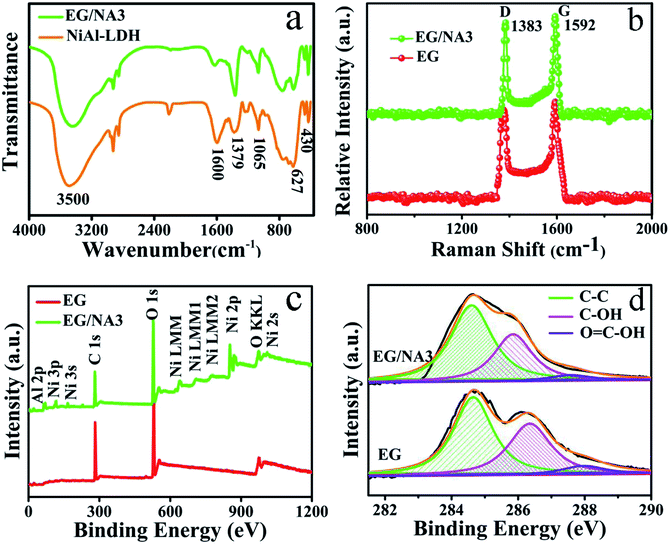 | ||
| Fig. 4 (a) FT-IR spectra of NiAl-LDH and EG/NA3; (b) Raman spectra of EG and EG/NA3; (c) XPS survey spectra of EG and EG/NA3; (d) C 1s XPS spectra of EG and EG/NA3. | ||
XPS studies further proved the chemical structures of EG and EG/NA3. EG contained only C and O elements, namely C 1s and O 1s at 282 eV and 530 eV, respectively (Fig. 4c). Compared with pure EG, the XPS spectrum of EG/NA3 nanowires exhibited Al 2p and Ni 2p peaks, in addition to C 1s and O 1s peaks. This result further confirmed the presence of NiAl-LDH in EG/NA3 nanowires. Fig. 4d depicts the C 1s XPS spectra of EG and EG/NA3. The C 1s region of EG was deconvoluted into three peaks. The peaks at 284.6, 286.6 and 288.2 eV were assigned to C–C, C–O and O![[double bond, length as m-dash]](https://www.rsc.org/images/entities/char_e001.gif) C–O.27,44 The peaks located at 286.6 and 288.2 eV were associated with oxygen-containing functional groups, which effectively generate anchoring sites for adsorption of inorganic nanomaterials during the hydrothermal reaction.45 In addition, for EG/NA3 composites, the peak intensities of 286.6 and 288.2 eV decreased, indicating that the number of oxygen-containing functional groups decreased during hydrothermal reaction.46,47
C–O.27,44 The peaks located at 286.6 and 288.2 eV were associated with oxygen-containing functional groups, which effectively generate anchoring sites for adsorption of inorganic nanomaterials during the hydrothermal reaction.45 In addition, for EG/NA3 composites, the peak intensities of 286.6 and 288.2 eV decreased, indicating that the number of oxygen-containing functional groups decreased during hydrothermal reaction.46,47
Gas sensing properties
It is well known that excellent charge transport performance plays a crucial role in the electrochemical performance of EG and NiAl-LDH.48 Similarly, for resistive gas sensors, the principle of gas detection is based on the change in electrical resistance of the sensing material after exposure to the target gas.In this work, NOx (the concentration ratio of NO2 and NO was 17![[thin space (1/6-em)]](https://www.rsc.org/images/entities/char_2009.gif) :
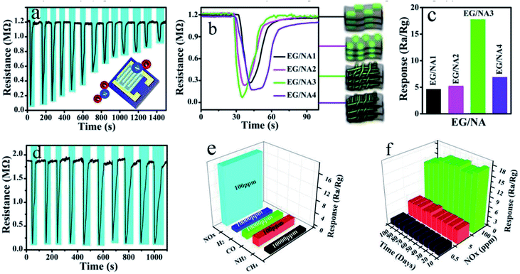
:![[thin space (1/6-em)]](https://www.rsc.org/images/entities/char_2009.gif) 5) was selected as the target analyte to evaluate the sensing performance of the obtained EG/NA3 at RT. Fig. 5a and b show the dynamic response of gas in EG/NA3 composite film sensor during cyclic exposure, with NOx concentrations ranging from 100 ppm to 0.01 ppm. Fig. 5a shows the typical response–recovery cycle curve for a sensor with lower NOx concentration. After injection of NOx gas, the resistance of the thin film sensor dropped sharply. After stabilization, the NOx was pumped out (injected into fresh air) and the resistance returned to the initial value, showing p-type semiconductor behavior. When the NOx concentration was 100 ppm, the response was as high as 17.65% and the response time was 2 s. It was found that the response gradually decreased as NOx concentration decreased, but response time was maintained within 6.6 s. In addition, the gas response and response time of EG/NA synthesized with different urea amounts were also investigated at RT, as shown in Fig. 5b, S2 and Table S1.† As expected, the EG/NA3 sensor exhibited an enhanced response to each NOx concentration in a given region compared to the other samples. For 100 ppm NOx, the response of the EG/NA3 sensor was 3.9, 3.4 and 2.6 times those of EG/NA1, EG/NA2 and EG/NA4, respectively (Fig. 5b). It can be seen more intuitively in the column chart in Fig. 4c. The reproducibility and reliability of EG/NA3 were further explored at the same NOx concentration. Fig. 5d shows a stable response to 100 ppm NOx for 10 cycles at RT. The response and recovery time exhibited no change after 10 consecutive cycles. These results strongly demonstrated that EG/NA3 nanocomposites are promising candidates for gas sensing applications.
5) was selected as the target analyte to evaluate the sensing performance of the obtained EG/NA3 at RT. Fig. 5a and b show the dynamic response of gas in EG/NA3 composite film sensor during cyclic exposure, with NOx concentrations ranging from 100 ppm to 0.01 ppm. Fig. 5a shows the typical response–recovery cycle curve for a sensor with lower NOx concentration. After injection of NOx gas, the resistance of the thin film sensor dropped sharply. After stabilization, the NOx was pumped out (injected into fresh air) and the resistance returned to the initial value, showing p-type semiconductor behavior. When the NOx concentration was 100 ppm, the response was as high as 17.65% and the response time was 2 s. It was found that the response gradually decreased as NOx concentration decreased, but response time was maintained within 6.6 s. In addition, the gas response and response time of EG/NA synthesized with different urea amounts were also investigated at RT, as shown in Fig. 5b, S2 and Table S1.† As expected, the EG/NA3 sensor exhibited an enhanced response to each NOx concentration in a given region compared to the other samples. For 100 ppm NOx, the response of the EG/NA3 sensor was 3.9, 3.4 and 2.6 times those of EG/NA1, EG/NA2 and EG/NA4, respectively (Fig. 5b). It can be seen more intuitively in the column chart in Fig. 4c. The reproducibility and reliability of EG/NA3 were further explored at the same NOx concentration. Fig. 5d shows a stable response to 100 ppm NOx for 10 cycles at RT. The response and recovery time exhibited no change after 10 consecutive cycles. These results strongly demonstrated that EG/NA3 nanocomposites are promising candidates for gas sensing applications.
In order to be well applied in practice and industrially, selectivity and stability are two important factors to consider when preparing gas sensors.49,50 As shown in Fig. 5e, the selectivity of the prepared EG/NA3 sensor was tested by H2, CO, CH4 and NH3 gases. The measured response for 100 ppm NOx (17.65) was much higher than that for 100 ppm NH3 (1.4), while the sensor was almost unresponsive to H2, CO and CH4 at the same concentration. The sensor's gas response to NOx was much higher than several other gases, mainly because NOx reacts with absorbed oxygen (O2−) at RT.51,52 The sensor was placed in air at RT for 72 h to verify the stability of the EG/NA3. The resistance of the EG/NA3 sensor was then tested for 100, 5, and 0.5 ppm NOx gas every 10 days at RT (Fig. 5f). The results showed that the EG/NA3 composite was stable to NOx gas and could be stable for up to 100 days at any concentration. Based on the above analysis, we believe that the EG/NA3 nanowire sensor may be suitable for detection of NOx in real life environments.
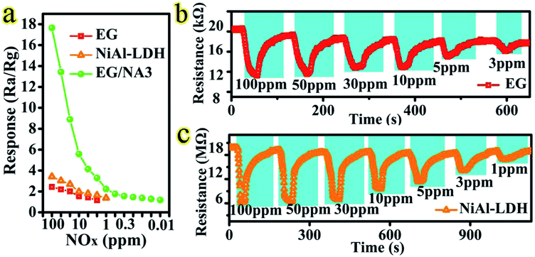
In addition, the sensing properties of EG, NiAl-LDH and EG/NA3 samples were investigated. In Fig. 6 and Table S2,† the EG/NA3 composite sensor shows faster response to different concentrations of NOx and a faster response/recovery time compared to the other two sensors. For 100 ppm NOx, the response of the EG/NA3 sensor was approximately 8 times that of EG and NiAl-LDH. The EG/NA3 sensor also had faster response–recovery times of 2 s and 9.3 s, respectively (see Table S2†). The enhanced of response was due to the synergy between EG and NiAl-LDH (NiAl-LDH nanowires and assembly network of EG). Therefore, the electrical properties of the three samples were further studied.
MS and EIS analyses
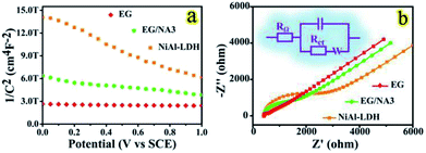
MS measurements were carried out to study the effect of doping on gas sensing performance.53 Fig. 7a shows an MS plot of the electrodes for the EG, EG/NA3 and NiAl-LDH samples. All samples showed a negative slope in the MS plot and thus all have p-type semiconductor behavior. This was consistent with the results of the dynamic response curves of the EG/NA3 sensor. The carrier density was calculated by eqn (1):| Nd = (−2/e0εε0)[d(1/C2)/dV]−1 | (1) |
It has been well known that the resistance of materials plays a crucial role in their sensing process; appropriate resistance and electron transport in air result in better gas sensitivity.56 Therefore, EIS of the EG, NiAl-LDH and EG/NA3 composites was carried out, as shown in Fig. 7b. Here, RΩ denotes the uncompensated bulk resistance of the electrolyte, separator and electrode. Rct was attributed to the charge transfer resistance at the interface of the active material; C is a long phase angle element, involving double layer capacitance. The semicircle in the high frequency range was related to the surface properties of the electrode, corresponding to Rct. The impedance of the EG/NA3 electrode was between pure EG and NiAl-LDH (see Table S3†). This result was consistent with MS analysis. Therefore, according to MS and EIS analysis, an improvement in sensing performance was expected due to an improvement in carrier density of the EG/NA3 composites.
Discussion of sensing mechanism
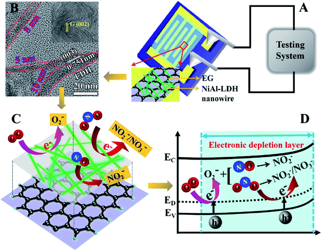
Many researchers have proved that adsorption of NOx molecules on the surface of EG is mainly carried out by weak van der Waals interactions.57,58 When the surface of EG was modified by NiAl-LDH, the response of the sensor to NOx gas was significantly enhanced. Compared with the weak interaction of NOx and EG, it could be reasonably concluded that the interaction between NOx molecules and NiAl-LDH nanowires was more intense and the synergy between EG and NiAl-LDH played an important role.The proposed gas sensing mechanism is illustrated in Scheme 2A–D. The gas sensing mechanism of the EG/NA3 sensor should follow the surface charge model, as explained by the change in resistance of EG/NA3 sensor when exposed to different gas environments.46 Oxygen adsorption played an important role in charge transport of EG/NA3. To the best of our knowledge, semiconductors typically react with O2 during semiconductor sensor operation, resulting in the formation of oxygen species (such as O2−) on their surfaces and grain boundaries under an air atmosphere.59 These adsorbates formed a space charge region inside the semiconductor and formed an electron depletion layer due to electron transfer onto the surface-adsorbed oxygen.
When EG/NA3 was exposed to air, O2 could easily capture free electrons from the conduction band or donor level of EG/NA3 to form an oxygen adsorbate (O2−), which could improve the performance of NOx sensors (reaction (2)). When exposed to NOx, NOx was directly adsorbed on EG/NA3 and reacted with O2− to form NO2− (reaction (3)–(5)). As the interaction time prolonged, NO2− became partially NO3− in reaction (6). This process captured electrons from the conduction band or donor level of NiAl-LDH, resulted in a decrease in electron density, and finally increased the hole carrier density on the semiconductor surface due to electron loss.60 From the results of electrochemical tests and gas sensitivity tests, we learned that EG/NA3 exhibited p-type semiconductor behavior. The increase in hole density caused a decrease in semiconductor resistance, which eventually led to a rapid decline in resistance (see Fig. 5).
| O2 + e− → O2− | (2) |
| NO2 + e− → NO2− | (3) |
| NO2 + O2− → NO2− + 2O | (4) |
| NO + O2− → NO2− + O | (5) |
| NO2− + O → NO3− | (6) |
The gas sensing mechanism was primarily due to the direct charge transfer between the NOx molecule and the sensing material, once the target gas was absorbed by the sensor. Since EG behaved as a typical p-type semiconductor and the oxidized NOx acted as an electron acceptor, NOx absorption resulted in an increase in hole density and an increase in conductivity. In summary, the high performance of the EG/NA3 gas sensor for NOx could be attributed to three factors. First, in addition to improving the conductivity of the sensor element, the multilayer EG substrate also produced an effective Schottky contact at the interface with NiAl-LDH, which greatly enhanced the gas sensing performance.61,62 Second, the slit holes between the parallel layers of multilayer EG and the pores formed by the interdigitated NiAl-LDH nanowires in the EG interlayer might enhance gas sensing performance. The slit holes and pores could act as channels for gas diffusion, thus providing more active sites for the reaction of NOx with surface adsorbed oxygen species. Third, the NiAl-LDH nanowires shortened the gas transport path and resulted in a higher surface area for the EG/NA3 composites. Therefore, they increased the number of active adsorption sites and enhanced the interaction between the NOx molecule and EG/NA3.
Conclusions
In summary, this work developed a new synthesis of microwave heating-vacuum assisted-hydrothermal method, using EG as a template and changing urea loading in the hydrothermal reaction to control the assembly structure of expanded graphite/NiAl-LDH. The expanded EG plate provided anchor sites for NiAl-LDH nanosheets and the expanded graphite/NiAl-LDH nanowire composites exhibited improved sensing performance for NOx compared with different forms of NiAl-LDH and pure EG at RT. In particular, the EG/NA3 sensor had fast response/recovery behavior, good selectivity, detection limits as low as 10 ppb for NOx, and excellent gas sensing response (100 ppm, ∼17.65%) to NOx in air at RT. The enhanced gas sensing properties were attributed to the excellent electrical conductivity of the EG and the synergistic effect of the nanostructure of NiAl-LDH. The results demonstrated a new method for controlling the assembly structure of LDH materials and this work is expected to broaden the research scope of LDH and graphene materials in practical applications.Conflicts of interest
There are no conflicts to declare.Acknowledgements
This work was supported by the National Natural Science Foundation of China (No. 21671060; 2167010747); the Program for Innovative Research Team in Chinese Universities (IRT1237); and the National Natural Science Foundation of Heilongjiang Province (No. D2015003).Notes and references
- E. X. Wu, Y. Xie, B. Yuan, H. Zhang, X. D. Hu, J. Liu and D. H. Zhang, ACS Sens., 2018, 3, 1719–1726 CrossRef CAS PubMed.
- J. Z. Ou, W. Y. Ge, B. Carey, T. Daeneke, A. Rotbart, W. Shan, Y. C. Wang, Z. Q. Fu, A. F. Chrimes, W. Wlodarski, S. P. Russo, Y. X. Li and K. Kalantar-zade, ACS Nano, 2015, 9, 10313–10323 CrossRef CAS PubMed.
- S. De, N. Venkataramani, S. Prasad, R. O. Dusane, L. Presmanes, Y. Thimont, P. Tailhades, V. Baco-Carles, C. Bonningue, T. P. Sumangala and A. Barnabé, IEEE Sens. J., 2018, 18, 6937–6945 CAS.
- J. Y. Wang, T. P. Zhang, M. Li, Y. Yang, P. Lu, P. Ning and Q. Wang, RSC Adv., 2018, 8, 22694–22709 RSC.
- X. L. Wu, L. Wang, C. L. Chen, A. W. Xu and X. K. Wang, J. Mater. Chem., 2011, 21, 17353–17359 RSC.
- Y. F. Zhao, X. D. Jia, G. B. Chen, L. Shang, G. I. N. Waterhouse, L. Z. Wu, C. H. Tung, D. O'Hare and T. R. Zhang, J. Am. Chem. Soc., 2016, 138, 6517–6524 CrossRef CAS PubMed.
- X. Wang, R. Y. Cao, S. W. Zhang, P. Y. Hou, R. X. Han, M. H. Shao and X. J. Xu, J. Mater. Chem. A, 2017, 5, 23999–24010 RSC.
- J. J. Zhang, P. G. Tang, T. Y. Liu, Y. J. Feng, C. Blackman and D. Q. Li, J. Mater. Chem. A, 2017, 5, 10387–10397 RSC.
- Y. Seekaew, A. Wisitsoraat, D. Phokharatkul and C. Wongchoosuk, Sens. Actuators, B, 2019, 279, 69–78 CrossRef CAS.
- Z. Y. Chu, H. X. Sun, H. Xu, J. Zhou, G. Zhang, Y. Xie, L. Li and K. Y. Shi, RSC Adv., 2015, 5, 101760–101767 RSC.
- Z. B. Ye, Y. Chen, B. H. Liu, Y. J. Su, Z. Chen, H. L. Tai and Y. D. Jiang, ECS J. Solid State Sci. Technol., 2018, 7, Q3148–Q3152 CrossRef CAS.
- Y. X. Gong, Y. Wang, G. Sun, T. K. Jia, L. Jia, F. M. Zhang, L. Lin, B. Q. Zhang, J. L. Cao and Z. Y. Zhang, Nanomaterials, 2018, 8, 132 CrossRef PubMed.
- S. Mao, G. H. Lu and J. H. Chen, J. Mater. Chem. A, 2014, 2, 5573–5579 RSC.
- Z. H. Xiao, L. B. Kong, S. C. Ruan, X. L. Li, S. J. Yu, X. Y. Li, Y. Jiang, Z. J. Yao, S. Ye, C. H. Wang, T. S. Zhang, K. Zhou and S. Li, Sens. Actuators, B, 2018, 274, 235–267 CrossRef CAS.
- S. W. Lee, W. Lee, Y. Hong, G. Lee and D. S. Yoon, Sens. Actuators, B, 2018, 255, 1788–1804 CrossRef CAS.
- L. L. Liu, M. Cheng and Z. H. Yang, Electrochim. Acta, 2018, 277, 67–76 CrossRef CAS.
- M. F. P. Duarte, I. M. Rocha, J. L. Figueiredo, C. Freire and M. F. R. Pereira, Catal. Today, 2018, 301, 17–24 CrossRef CAS.
- T. Sirinupong, W. Youravong, D. Tirawat, W. J. Lau, G. S. Lai and A. F. Ismail, Arabian J. Chem., 2018, 11, 1144–1153 CrossRef CAS.
- Y. Liu, Y. G. Xu, B. H. Fan, M. H. Yang, A. L. Hamon, P. Haghi-Ashtiani, D. L. He and J. B. Bai, Chem. Phys. Lett., 2018, 71, 189–193 CrossRef.
- P. Kumar, S. Som, M. K. Pandey, S. Das, A. Chanda and J. Singh, J. Alloys Compd., 2018, 744, 64–74 CrossRef CAS.
- Y. Khosravi, M. Sasar and Y. Abdi, Mater. Sci. Semicond. Process., 2018, 85, 9–14 CrossRef CAS.
- A. C. Ferrari, F. Bonaccorso and V. Fal’ko, et al., Nanoscale, 2015, 7, 4598–4810 RSC.
- A. R. Cadore, E. Mania, A. B. Alencar, N. P. Rezende, S. de Oliveira, K. Watanabe, T. Taniguchi, H. Chacham, L. C. Campos and R. G. Lacerda, Sens. Actuators, B, 2018, 266, 438–446 CrossRef CAS.
- X. C. Zhang, H. Zhong, L. D. Xu, S. H. Wang, H. Z. Chi, Q. J. Pan, G. Zhang and A. Q. Wang, Mater. Res. Bull., 2018, 102, 108–115 CrossRef CAS.
- P. Lu, Y. Liu, T. T. Zhou, Q. Wang and Y. S. Li, J. Membr. Sci., 2018, 567, 89–103 CrossRef CAS.
- K. Azadmanjiri, V. K. Srivastava, P. Kumar, M. Nikzad, J. Wang and A. Y. Yu, J. Mater. Chem. A, 2018, 6, 702–734 RSC.
- J. Memon, J. H. Sun, D. L. Meng, W. Z. Ouyang, M. A. Memon, Y. Huang, S. K. Yan and J. X. Geng, J. Mater. Chem. A, 2014, 2, 5060–5067 RSC.
- P. K. Sandhya, J. Jose, M. S. Sreekala, M. Padmanabhan, N. Kalarikkal and S. Thomas, Ceram. Int., 2018, 44, 15092–15098 CrossRef CAS.
- X. Bai, Q. Liu, H. S. Zhang, J. Y. Liu, Z. S. Li, X. Y. Jing, Y. Yuan, L. H. Liu and J. Wang, Electrochim. Acta, 2016, 215, 492–499 CrossRef CAS.
- L. B. Chen, C. C. Li, Y. H. Wei, G. Zhou, A. Q. Pan, W. F. Wei and B. Y. Huang, J. Alloys Compd., 2016, 687, 499–505 CrossRef CAS.
- X. J. Li, Y. Zhang, W. Xing, L. Li, Q. Z. Xue and Z. F. Yan, J. Power Sources, 2016, 331, 67–75 CrossRef CAS.
- Y. L. Yong, H. Jiang, X. H. Li, S. J. Lv and J. X. Cao, Phys. Chem. Chem. Phys., 2016, 18, 21431–21441 RSC.
- F. Schipani, D. R. Miller, M. A. Ponce, C. M. Aldao, S. A. Akbar, P. A. Morris, J. C. Xu and Y. D. Wang, Sens. Actuators, B, 2017, 241, 99–108 CrossRef CAS.
- X. Y. Yu, T. Luo, Y. Jia, R. X. Xu, C. Gao, Y. Y. Zhang, J. H. Liu and X. J. Huang, Nanoscale, 2012, 4, 3466–3474 RSC.
- X. M. Tao, D. L. Liu, W. W. Cong and L. Huang, Appl. Surf. Sci., 2018, 457, 572–579 CrossRef CAS.
- J. Yang, C. Yu, X. M. Fan and J. S. Qiu, Adv. Energy Mater., 2014, 1400761 CrossRef.
- X. Wu, C. Ci, Y. L. Du, X. Z. Liu, X. J. Li and X. M. Xie, Mater. Chem. Phys., 2018, 211, 72–78 CrossRef CAS.
- H. Tian, W. T. Bao, Y. Jiang, L. Wang, L. Zhang, O. Sha, C. Q. Wu and F. M. Gao, Chem. Eng. J., 2018, 354, 1132–1140 CrossRef CAS.
- L. F. Wei, J. Z. Ma, W. B. Zhang, C. Liu and Y. Bao, Prog. Org. Coat., 2018, 122, 64–71 CrossRef CAS.
- C. Baudín, T. Benet and P. Pena, J. Mech. Behav. Biomed. Mater., 2019, 89, 33–47 CrossRef PubMed.
- N. Zhang, Y. Huang, M. Y. Wang, X. D. Liu and M. Zong, J. Colloid Interface Sci., 2019, 534, 110–121 CrossRef CAS PubMed.
- M. Y. Miao, J. T. Feng, Q. Jin, Y. F. He, Y. N. Liu, Y. Y. Du, N. Zhang and D. Q. Li, RSC Adv., 2015, 5, 36066–36074 RSC.
- A. Hosseinzadeh, S. Bidmeshkipour, Y. Abdi, E. Arzi and S. Mohajerzadeh, Appl. Surf. Sci., 2018, 448, 71–77 CrossRef CAS.
- Q. P. Kong, J. Y. Wei, Y. Hu and C. H. Wei, J. Hazard. Mater., 2019, 363, 161–169 CrossRef CAS PubMed.
- Y. X. Xu, K. X. Sheng, C. Li and G. Q. Shi, ACS Nano, 2010, 4, 4324–4330 CrossRef CAS PubMed.
- Y. Yang, C. G. Tian, J. C. Wang, L. Sun, K. Y. Shi, W. Zhou and H. G. Fu, Nanoscale, 2014, 6, 7369–7378 RSC.
- Y. Yang, C. G. Tian, L. Sun, R. J. Lu, W. Zhou, K. Y. Shi, K. Kan, J. C. Wang and H. G. Fu, J. Mater. Chem. A, 2013, 1, 12742–12749 RSC.
- C. J. Zhou, H. L. Zhu, Y. P. Wu, W. Lin, W. H. Yang and L. X. Dong, Mater. Chem. Phys., 2017, 198, 49–56 CrossRef CAS.
- A. I. Ayesh, R. E. Ahmed, M. A. Al-Rashid, R. A. Alarrouqi, B. Saleh, T. Abdulrehman, Y. Haik and L. A. Al-Sulaiti, Sens. Actuators, A, 2018, 283, 107–112 CrossRef CAS.
- J. Zhang, Z. Y. Qin, D. Zeng and C. S. Xie, Phys. Chem. Chem. Phys., 2017, 19, 6313–6329 RSC.
- R. Godbole, V. P. Godbole, P. S. Alegaonkar and S. Bhagwat, New J. Chem., 2017, 41, 11807–11816 RSC.
- C. Balamurugan, S. J. Song and D. W. Lee, Sens. Actuators, B, 2018, 272, 400–414 CrossRef CAS.
- A. Adan-Mas, T. M. Silva, L. Guerlou-Demourgues and M. F. Montemor, Electrochim. Acta, 2018, 289, 47–55 CrossRef CAS.
- J. C. Wang, L. L. Wang, J. Gao, L. Zhou, Y. L. Ge, L. Q. Jing, K. Y. Shi and L. Li, J. Mater. Sci.: Mater. Electron., 2015, 26, 6612–6624 CrossRef CAS.
- P. Kumar, R. Boukherroub and K. Shankar, J. Mater. Chem. A, 2018, 6, 12876–12931 RSC.
- X. D. Hao, D. J. Wu, Y. P. Wang, J. H. Ouyang, J. Wang, T. Liu, X. S. Liang, C. Zhang, F. M. Liu, X. Yan, Y. Gao and G. Y. Lu, Sens. Actuators, B, 2019, 278, 1–7 CrossRef CAS.
- R. K. Joshi, H. Gomez, F. Alvi and A. Kumar, J. Phys. Chem. C, 2010, 114, 6610–6613 CrossRef CAS.
- J. D. Fowler, M. J. Allen, V. C. Tung, Y. Yang, R. B. Kaner and B. H. Weiller, ACS Nano, 2009, 3, 301–306 CrossRef CAS PubMed.
- Y. Seekaew, A. Wisitsoraat, D. Phokharatkul and C. Wongchoosuk, Sens. Actuators, B, 2019, 279, 69–78 CrossRef CAS.
- N. Tammanoon, A. Wisitsoraat, C. Sriprachuabwong, D. Phokharatkul, A. Tuantranont, S. Phanichphant and C. Liewhiran, ACS Appl. Mater. Interfaces, 2015, 7, 24338–24352 CrossRef CAS PubMed.
- S. Z. Deng, V. Tjoa, H. M. Fan, H. R. Tan, D. C. Sayle, M. Olivo, S. Mhaisalkar, J. Wei and C. H. Sow, J. Am. Chem. Soc., 2012, 134, 4905–4917 CrossRef CAS PubMed.
- Z. Y. Zhang, R. J. Zou, G. S. Song, L. Yu, Z. G. Chen and J. Q. Hu, J. Mater. Chem., 2011, 21, 17360–17365 RSC.
Footnote |
| † Electronic supplementary information (ESI) available. See DOI: 10.1039/c9ra00526a |
| This journal is © The Royal Society of Chemistry 2019 |

