 Open Access Article
Formation of highly ordered micro fillers in polymeric matrix by electro-field-assisted aligning†
Yajun Zhanga,
Xiangwen Zhenga,
Weitao Jiang *a,
Jie Hana,
Jiangtao Pua,
Lanlan Wanga,
Biao Leia,
Bangdao Chenab,
Yongsheng Shia,
Lei Yina,
Hongzhong Liu
 *a,
Feng Luoac,
Xiaokang Liud and
Jinju Chene
aState Key Laboratory for Manufacturing Systems Engineering, Xi'an Jiaotong University, Xi'an 710054, China. E-mail: wtjiang@mail.xjtu.edu.cn; hzliu@mail.xjtu.edu.cn
bShaanxi Joint Laboratory for Graphene, China
cIMDEA Nanoscience, Faraday 9, Ciudad Universitaria de Cantoblanco 28049, Madrid, Spain
dEngineering Research Center of Mechanical Testing Technology and Equipment, Chongqing University of Technology, Chongqing 400050, China
eSchool of Engineering, Newcastle University, UK
First published on 15th May 2019
Abstract
Nanocomposites composed by polymeric matrix with micro/nano fillers have drawn lots of attention since their dramatic properties beyond pristine polymers. The spatial distribution of the micro/nano fillers in the polymeric matrix determines the final desired properties of the nanocomposites, thus deserves to investigate. Here, we proposed an effective method of assembling the micro/nano fillers to pre-designed patterns within the polymeric matrix by AC-electro-field-assisted aligning. By pre-designed AC electric fields which could be dynamically controllable, the distribution of microparticles (acting as fillers) in the matrix was tuned to various patterns related to the electric fields, such as linear alignment and circular alignment. The field-oriented particles chains could act as endoskeletal structures, showing unique properties (i.e., mechanical, optical, and anisotropic properties) beyond those of the conventional composites with randomly distributed particles.
Introduction
In the past few decades, nanocomposites have been widely studied in scientific literature since their significant improvement in performance, even in the case of low micro/nano fillers content. By the rational selection of fillers, it is possible to control the basic properties of the material,1–6 such as melting temperature, magnetic properties, charge capacity, and color, without changing the chemical composition. Performances improvement and optimization based on micro/nano fillers promise extensive applications in many fields such as mechanical reinforcement,7,8 lightweight components,9 sensors,10,11 and etc. The fillers can be three-dimensional framework, two-dimensional, one-dimensional and even zero-dimensional materials. Besides the species, the distribution of the micro/nano fillers in the matrix is also a key factor affecting nanocomposites properties. In recent years, a large number of theoretical and experimental studies have proved that the distribution of fillers in nanocomposites has an important influence on the yield intensity, plastic deformation, dielectric constant and effective thermal conductivity, etc. In view of this, a variety of heterogeneous structures are applied to nanocomposites, and are widely used in the fields of local strength enhancement, directional bending deformation, nonlinear optics, etc. Nevertheless, the distribution and the manipulation of the embedded particles for modulating the macroscopic properties of the composites, remain a primal barrier to the more ubiquitous application of nanocomposites.At present, there are many ways to control the distribution of fillers, including mechanical, chemical and physical approaches, etc.12 Mechanical methods mainly include ultrasonic mixing,13,14 high shear mixing in solution15 and ball milling between solid particles.16,17 These methods use high energy vibration or shear force to separate fillers from each other. Since the high input energy and large mechanical force, the mechanical methods often induce unpredictable defects in the filler structure. By contrast, chemical methods have been widely employed to improve the compatibility and interaction force between the fillers and the polymeric matrix, such as the grafting of organosilanes,18–21 although their aggressive effects need further improved. In terms of physical methods, field-assisted technology is an effective way to manipulate the orientation of fillers, thus modulating the functionality and intelligence of materials. External fields usually include electric fields,22–24 magnetic fields25–28 and temperature fields,29–31 etc., in which electric fields and magnetic fields are often used to manipulate the direction of fillers distribution. Gao32 developed a 1D assembly array of single particle resolution with controlled length and well-behaved configuration, which was prepared via inkjet printing method assisted with magnetic guiding. Owing to the high-aspect-ratio characteristic of the assembled structure, the as-prepared 1D arrays could be used for magnetic field sensing with anisotropic magnetization. Morales33 reported a soft thermoresponsive hydrogel with common latex microspheres assembled and patterned by AC electric fields. The field-oriented particles chains could guide the macroscopic bending pattern of the actuators. Qiang34 proposed and fabricated a hierarchical hydrogel with the charged silk nanofibers aligned due to the electrostatic interactions between the charged silk nanofibers and the electric fields. When combined with the biocompatibility of silk, the aligned hydrogel systems could have broad utility in biological systems. Although the aligning of micro/nano fillers could be achieved in previous studies, it is still desired to develop new methods to manipulate the spatial distribution patterns of the micro/nano fillers in the polymeric matrix, supplying a new route for composites research. Furthermore, exploiting a new strategy to fabricate particles assembly with controllable particles arrangement and well-behaved configuration in a simple and effective approach is still a great challenge.
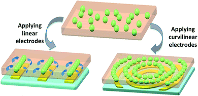
Herein, a simple and rapid method based on AC electric fields is proposed to produce patterned assemblies of particles in a controllable manner. In this study, taking polystyrene (PS) microparticles as fillers, we introduced dielectrophoresis (DEP) into the spatial distribution of fillers. DEP is the motion of an object under the force resulting from an electric fields gradient. One of its major features is the ability to manipulate particles. Via pre-designed AC electric fields, the PS particles orderly aligned into desired patterns under the DEP force, as shown in Fig. 1. The desired particles patterns act as the endoskeletal structures of polymeric matrix, which endows matrix with anisotropic functionality that randomly distributed particles are unable to reach.
Experimental
Fabrication of electrodes and sealed chamber device
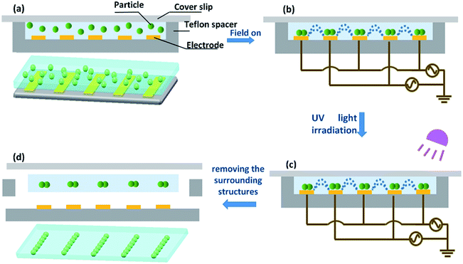
Au electrodes were fabricated by photolithography.35–38 The SU-8 photoresist (SU-8 2050, MicroChem Corporation) was spin-coated onto a glass slide. After soft baked, a standard lithography process was performed and the SU-8 photoresist was patterned. After that, a 30 nm Cr layer was deposited as the adhesive layer, and then a 100 nm Au layer was deposited as the conductive layer. Finally, the glass slide was immersed in acetone, and the electrodes patterns were revealed. For the sealed chamber device, as shown in Fig. 2a, the electrode with 40 μm width and 40 μm gap was applied as the bottom support, and a thin glass sheet (20 mm × 20 mm × 100 μm) was used as the cover slip. A 50 μm-thick Teflon film was used as the spacer between the electrode and the glass cover slip.Arrangement of microparticles
The polymeric matrix is composed of 1,6-hexanediol diacrylate (HDDA) and photoinitiator (1173), and the monomer concentration of photoinitiator was fixed 0.2%. The PS particles (5 μm in diameter, purchased from Tianjin Saierqun Technology Co., Ltd.) were dispersed in deionized water. After the water was completely evaporated at 60 °C, the polymeric matrix was added to the reagent bottle containing PS particles, and ultrasonic vibration was carried out for 2 hours at room temperature to obtain a uniformly dispersed PS particles solution. After that, the solution was rapidly injected into the sealed chamber device. A sinusoidal AC signal (5 MHz, 20 Vpp), generated by a waveform generator (Unit UTG2062A), was applied to electrodes lines to create a non-uniform electric field. A digital phosphor oscilloscope (Tektronix DPO 3034) was used to confirm the generated waveform. The viscometer SCYN1301 was used to measure the kinematic viscosity of the solution. The DEP-induced behavior of the microparticles was observed using an optical microscope (IX71, Olympus Co., Japan) equipped with a digital CCD camera and a computer screen.Immobilization of the particles chains
Induced by the structured electric field, PS particles instantaneously formed pre-designed distribution corresponding to electrodes in a few seconds, as shown in Fig. 2b. UV light at 365 nm was then applied to the solution with aligned particles chains for 120 s to allow photochemical polymerization and to immobilize aligned particles, as shown in Fig. 2c. The assembled particles patterns were preserved by polymerization in the absence of the electric fields. After irradiation of UV light, the cover slip above the chamber was removed, as shown in Fig. 2d, and then the Teflon film which acted as a spacer at the edge of the chamber was stripped. Finally, the cured matrix was peeled off from the surface of the electrodes and cleaned with deionized water at room temperature.Results and discussion
The mechanism of microparticles patterning based on n-DEP
In this paper, structured electric fields by pre-designed patterned electrodes is introduced to manipulate the distribution of the micro/nano fillers. DEP force, i.e., positive DEP (p-DEP) and negative DEP (n-DEP), induced by the structured electric fields,22,23 is used to drive the motion of PS particles in the polymeric matrix. The DEP force acting on a homogeneous dielectric particle suspended in the dielectric fluid medium (polymeric matrix) is given by| FDEP = 2πεma3Re[K(ω)]∇E2 | (1) |
 | (2) |
In this equation,  and
and  are the complex permittivities of the medium and the particle respectively, and
 | (3) |
Simulation of electric fields and particles dynamic distribution
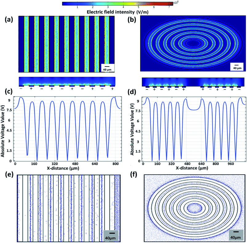
3D distribution of the structured electric field was calculated by the finite element method (FEM) solver (COMSOL Multiphysics). A sinusoidal AC voltage (5 MHz, 20 Vpp) was applied to the pre-designed patterned electrodes, i.e., interdigital electrodes, serpentine electrodes, and gradient electrodes. The different electric fields for patterned electrodes were shown in Fig. 3a, b and S1a,† both in the horizontal and vertical planes. In the vertical planes, the voltage, which determined the DEP force applied on the micro/nano fillers, varied with the distance away from the electrodes surface. A plane at 5 μm away from the electrodes surface was selected and its voltage distribution was shown in Fig. 3c, d, S1b and Fig. S2.† It was clearly indicated that, the valleys of the applied electric fields were generated right above the electrodes lines, and the peaks were found between the electrodes lines, forming structured electric fields.The structured electric fields, determined by the pre-designed patterned electrodes, showed an important role on the spatial distribution of PS particles. In order to investigate the dynamic manipulation for the particles, a simulation model was established. The simulation results indicated that, under the n-DEP force, particles uniformly suspended in the polymeric matrix were rapidly repelled to the valleys in a few seconds by strong electric fields formed in localized areas, and aggregated into chains above electrodes lines, as shown in Fig. 3e, f, S3 and Movie 1.†
Characterization of the patterned electrodes
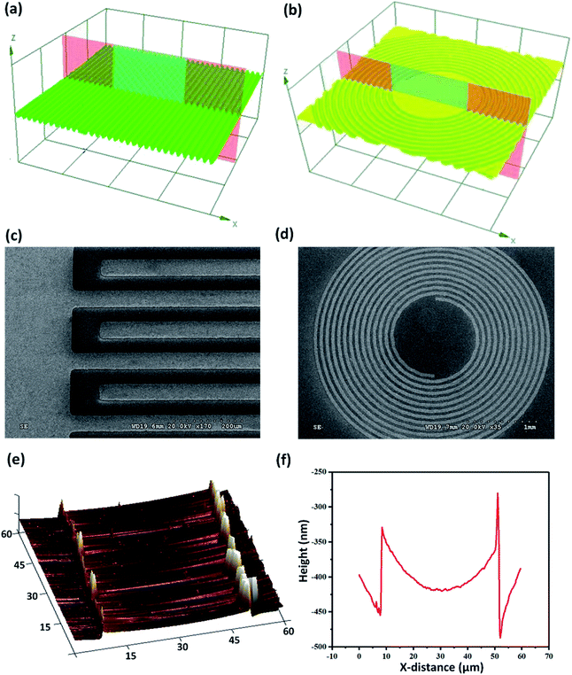
The arrangement pattern of the particles was greatly affected by the shape of electrodes, which indicated that the expected particles pattern could be obtained by reasonable pre-design of the electrodes. The Au electrodes with good conductivity were fabricated by photolithography. The surfaces of the electrodes were observed by the laser scanning confocal microscope (LSCM) and scanning electron microscope (SEM). The three-dimensional images of the surfaces were shown in Fig. 4a and b. The SEM pictures were shown in Fig. 4c and d. In addition, the surface roughness of electrodes was also important, and the uneven surfaces might affect the distribution of electric fields. Atomic force microscope (AFM) was used to characterize the roughness. The AFM picture was shown in Fig. 4e, and the numerical curve of the surface roughness was shown in Fig. 4f. Via these pictures, it was found that the surfaces were uniform with a small roughness.Morphological characterization of particles chains
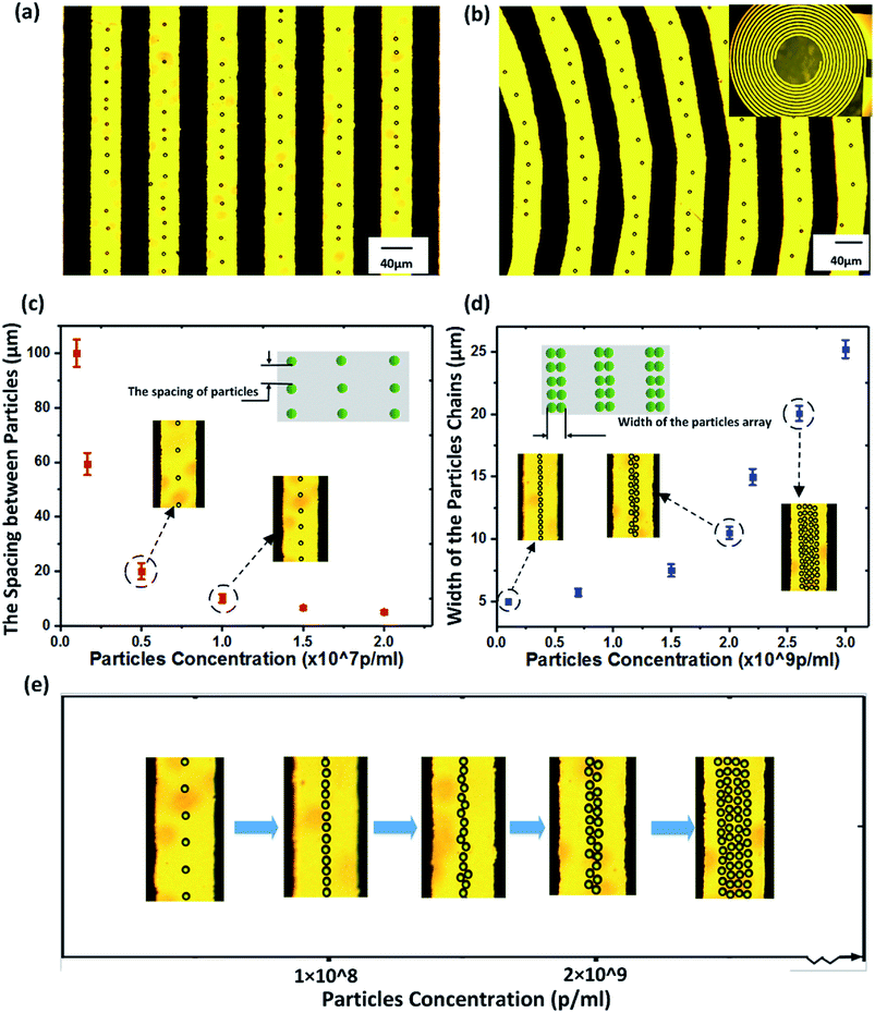
In experiments, the chains formed by PS particles were shown in Fig. 5a, b and Movie 2.† It was found that the morphology of particles chains was closely related to the concentration of particles in solution. A large spacing between particles was found in the assembled particles chains for low concentration, and it decreased gradually as the concentration increased, as shown in Fig. 5c. Furthermore, the width of the chains, mainly implying the assembly columns of the particles, was also directly affected by the concentration, and the relation of width versus concentration was shown in Fig. 5d. The change process of particles distribution determined by the concentration was clearly shown in Fig. 5e. It was indicated that, when concentration was below 108 particles per mL (p per mL), sparse columns with large spacing were found. As concentration increased, the particles chains gradually evolved from sparse columns to the dense columns with crowded particles, and the columns width gradually increased when the concentration was over 2 × 10⁹ p per mL.Spatial distribution of particles
In order to study the spatial distribution of particles in the polymeric matrix, the method of slicing the light-cured matrix was implemented. The distribution of particles in the vertical plane was shown in Fig. 6a. It was found that the kinematic viscosity of the solution and the applied voltage played important roles on the distribution height over the electrodes surface in the polymeric matrix. The kinematic viscosity was a mensuration of the internal friction force of a fluid as it flowed, which would hinder the dynamic motion of particles in the fluid. In the experiment, a variety of solutions with different viscosities were used to verify the effect of dynamic viscosity on particles distribution. The height variation with the kinematic viscosity at different applied voltages was shown in Fig. 6b. At the same voltage, when the viscosity was less than 9 mm2 s−1, the height increased sharply with the viscosity. When the viscosity increased from 9 mm2 s−1 to 25 mm2 s−1, the effect of viscosity on height was found to be weakened, and the height increased slowly with the viscosity. When the viscosity was over 25 mm2 s−1, the movement of particles was greatly hindered and no longer aligned, and the height appeared to grow faster again, which might be attributed to the sharp decrease of the electric field force since the great height, and the fluid resistance to particles occupied the dominant position.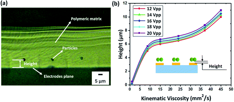 | ||
| Fig. 6 (a) The distribution of particles in the vertical plane; (b) the height variation with the kinematic viscosity at different applied voltages. | ||
It is well known that the properties of composites depend on the microstructure to a certain extent. Thus, it is significant to study the effects of the micro/nano fillers distribution on the composites performances, which could supply guidelines to develop high-performance composites. Expected performances can be achieved by utilizing and changing micro/nano fillers alignment. In addition, by studying the distribution height of particles in the matrix, the range of electric fields manipulating particles was revealed, which is hopeful to be applied in the multi-layer alignment of particles, and might offer a promising method to control the performance of each layer when combined with 3D printing technology. All these results have important guiding significance for breaking the bottleneck of composite performance improvement.
Conclusions
In this study, based on n-DEP mechanism, the method of field-assembled was utilized to fabricate highly ordered particles chains in polymeric matrix, which had excellent particles controllability, rapid responsiveness, and allowed particles to be aligned in directional areas. As endoskeletal structures, the field-oriented particles chains could have anisotropic response to the external stimuli, which provides promising applications in soft robots and intelligent materials.Conflicts of interest
There are no conflicts to declare.Acknowledgements
This work is supported by the National Natural Science Foundation of China (No. 51625504, 51675421, 51427805, 91748209, 51827805) and the Joint fund of the Ministry of Education (6141A020224). This work is partially sponsored by National Key R&D Program of China (2016YFF0100700, 2017YFF0204803), Specialized Research Fund for the Doctoral Program of Higher Education (2018T111048), Major Science and Technology Special Project (2016ZX04002003, 2016ZX04002004) and the Natural Science Foundation of Shaanxi Province (2018ZDCXL-GY-08-01, 2017ZDXM-GY-112, 2017JZ014).Notes and references
- R. Bera, S. K. Karan, A. K. Das, S. Paria and B. B. Khatua, RSC Adv., 2015, 5, 70482–70493 RSC.
- L. S. Da, L. Germiniani and T. S. Plivelic, Soft Matter, 2018, 14, 1709–1718 RSC.
- A. Tiwari and S. J. Dhoble, RSC Adv., 2016, 6, 64400–64420 RSC.
- Z. Zang, X. Zeng, M. Wang, W. Hu, C. Liu and X. Tang, Sens. Actuators, B, 2017, 252, 1179–1186 CrossRef CAS.
- J. Chen, X. Huang, Y. Zhu and P. Jiang, Adv. Funct. Mater., 2017, 27, 1604754 CrossRef.
- V. D. Punetha, S. Rana, H. J. Yoo, A. Chaurasia, J. T. Mcleskey and M. S. Ramasamy, Prog. Polym. Sci., 2017, 67, 1–47 CrossRef CAS.
- J. Crosby-Alfred and L. Jong-Young, Polym. Rev., 2007, 47, 217–229 CrossRef.
- H. Wang, G. Xie, M. Fang, Z. Ying, Y. Tong and Y. Zeng, Composites, Part B, 2017, 113, 278–284 CrossRef CAS.
- H. Zhang, G. Zhang, J. Li, X. Fan, Z. Jing and J. Li, Compos. Appl. Sci. Manuf., 2017, 100, 128–138 CrossRef CAS.
- J. Xu, Y. Wang and S. Hu, Microchim. Acta, 2016, 184, 1–44 CrossRef.
- Y. Yan, S. V. Encadas, J. Zhang, G. Zu, D. Wei and Z. Jiang, Compos. Sci. Technol., 2017, 142, 163–170 CrossRef CAS.
- Z. Nie, A. Petukhova and E. Kumacheva, Nat. Nanotechnol., 2010, 5, 15–25 CrossRef CAS PubMed.
- A. D. Moghadam, E. Omrani, H. Lopez, L. Zhou, Y. Sohn and P. K. Rohatgi, Mater. Sci. Eng., A, 2017, 702, 312–321 CrossRef.
- X. Yin, S. Li, G. He, Y. Feng and J. Wen, Ultrason. Sonochem., 2018, 43, 15–22 CrossRef CAS PubMed.
- O. Oguz, K. Bilge, E. Simsek, M. K. Citak, A. A. Wis and G. Ozkoc, Ind. Eng. Chem. Res., 2017, 56, 8568–8579 CrossRef CAS.
- B. Almangour, D. Grzesiak and J. M. Yang, Powder Technol., 2018, 326, 467–478 CrossRef CAS.
- F. Delogu and G. Gorrasi, Prog. Mater. Sci., 2017, 86, 75–126 CrossRef CAS.
- S. L. Bee, M. A. A. Abdullah, M. Mamat, S. T. Bee, L. T. Sin and D. Hui, Composites, Part B, 2017, 110, 83–95 CrossRef CAS.
- S. Mallakpour and M. Madani, Prog. Org. Coat., 2015, 86, 194–207 CrossRef CAS.
- S. K. Kumar, N. Jouault, B. Benicewicz and T. Neely, Macromolecules, 2013, 46, 3199–3214 CrossRef CAS.
- T. Ji, C. Ma, L. Brisbin, L. Mu, C. G. Robertson and Y. Dong, Appl. Surf. Sci., 2017, 399, 565–572 CrossRef CAS.
- W. Liu, J. Shao, Y. Jia, Y. Tao, Y. Ding and H. Jiang, Soft Matter, 2015, 11, 8105–8112 RSC.
- M. Suzuki, T. Yasukawa, H. Shiku and T. Matsue, Langmuir, 2007, 23, 4088–4094 CrossRef CAS PubMed.
- H. J. Kim, J. Kim, Y. K. Yoo, J. H. Lee, J. H. Park and K. S. Hwang, Biosens. Bioelectron., 2016, 85, 977–985 CrossRef CAS PubMed.
- H. F. Le, F. Bouville, T. P. Niebel and A. R. Studart, Nat. Mater., 2015, 14, 1172–1179 CrossRef PubMed.
- R. M. Erb, R. Libanori, N. Rothfuchs and A. R. Studart, Science, 2012, 335, 199–204 CrossRef CAS PubMed.
- J. Y. Chung, J. G. Lee, Y. K. Baek, P. W. Shin and Y. K. Kim, Composites, Part B, 2017, 136, 215–221 CrossRef.
- Y. He, S. Yang, H. Liu, Q. Shao, Q. Chen and C. Lu, J. Colloid Interface Sci., 2018, 517, 40–51 CrossRef CAS PubMed.
- S. Deville, Adv. Eng. Mater., 2010, 10, 155–169 CrossRef.
- P. Munier, K. Gordeyeva, L. Bergstrom and A. B. Fall, Biomacromolecules, 2016, 17, 1875–1881 CrossRef CAS PubMed.
- M. Darder, P. Aranda, M. L. Ferrer, M. C. Gutiérrez, M. F. Del and E. Ruizhitzky, Adv. Mater., 2011, 23, 5262–5267 CrossRef CAS PubMed.
- M. Gao, M. Kuang, L. Li, M. Liu, L. Wang and Y. Song, Small, 2018, 14, 1800117 CrossRef PubMed.
- D. Morales, B. Bharti, M. D. Dickey and O. D. Velev, Small, 2016, 12, 2283–2290 CrossRef CAS PubMed.
- Q. Lu, S. Bai, Z. Ding, H. Guo, Z. Shao, H. Zhu and D. L. Kaplan, Adv. Mater. Interfaces, 2016, 3, 1500687 CrossRef.
- M. Suzuki, T. Yasukawa, Y. Mase, D. Oyamatsu, H. Shiku and T. Matsue, Langmuir, 2004, 20, 11005–11011 CrossRef CAS PubMed.
- S. C. Kilchenmann, E. Rollo, P. Maoddi and C. Guiducci, J. Microelectromech. Syst., 2016, 25, 425–431 Search PubMed.
- C. W. Hsu, F. C. Su, P. Y. Peng, H. T. Young, S. Liao and G. J. Wang, Sens. Actuators, B, 2016, 230, 559–565 CrossRef CAS.
- J. Wang, J. Jiu, T. Sugahara, S. Nagao, M. Nogi and H. Koga, ACS Appl. Mater. Interfaces, 2015, 7, 23297–23304 CrossRef CAS PubMed.
Footnote |
| † Electronic supplementary information (ESI) available. See DOI: 10.1039/c9ra00507b |
| This journal is © The Royal Society of Chemistry 2019 |

