DOI:
10.1039/C8RA10459J
(Paper)
RSC Adv., 2019,
9, 10465-10472
Alleviating concentration polarization: a micro three-electrode interdigitated glucose sensor based on nanoporous gold from a mild process†
Received
21st December 2018
, Accepted 7th March 2019
First published on 3rd April 2019
Abstract
Precisely detecting the concentration of glucose in the human body is an attractive way to prevent or diagnose diabetes. Compared with the traditional enzyme-based electrochemical glucose sensors, the non-enzymatic ones have gradually come to people's attention recently. By integrating three electrodes into one device, glucose sensors can achieve superior performance and are convenient to carry. Herein, a non-enzymatic three-electrode interdigitated glucose sensor (TEIDGS) based on nanoporous gold is designed and fabricated. To our best knowledge, it is the first time that interdigitated electrodes are combined in a single non-enzymatic glucose sensor device. Due to the advantage of the interdigitated structure and the smart design of the three-electrode circuit board, the TEIDGS can effectively reduce concentration polarization and achieve a high detective sensitivity for glucose of 1217 μA mM−1 cm−2 and 343 μA mM−1 cm−2 in the ranges of 0.001–0.590 mM and 0.59–7.00 mM, respectively. Moreover, a low detection limit of 390 nM can be reached. In addition, this TEIDGS possesses excellent selectivity for glucose among other interferents. Strikingly, after three weeks of operation, it can still retain a high detection performance. This work will certainly provide an efficient structure and proper catalytic material choice for future non-enzymatic glucose sensors.
1. Introduction
In a healthy human body, carbohydrates are converted into glucose, and glucose is absorbed into cells with the help of insulin, thus providing enough energy for daily activities. However, people who can't produce insulin or are unable to use insulin to carry glucose into their cells may suffer from diabetes. Nowadays, diabetes has become one of the most common diseases all around the world. According to the International Diabetes Federation, approximately 425 million adults (20–79 years) are living with diabetes and by 2045 this will rise to 629 million.1 In this view, accurate monitoring and controlling of the blood glucose concentration in real time is crucial for the fast diagnosis and timely treatment of diabetes. Therefore, glucose sensors with high sensitivity and stability, fast response and good selectivity are in demand.2
Electrochemical glucose sensors possess several properties including rapid response, high sensitivity, good selectivity and simplicity to use compared with other glucose sensors based on other techniques.3–5 Although the enzyme-based electro-chemical glucose sensors occupy a major place in the whole commercial industry, they have numerous limitations, in which the most severe one is that they are sensitive to the external environment due to the utilization of an enzyme. Thus, it has attracted many researchers' attention to develop high-performance non-enzymatic glucose sensors which can oxidize glucose directly on the electrode surface via applying a small voltage, avoiding the use of enzymes. It can overcome the problem of enzyme inactivation and shows the advantages of good stability, low cost, simplicity and reproducibility.4,6–9 Different kinds of materials have been applied to construct non-enzymatic glucose sensors including metals, alloys, metal oxides, and carbon.10–15 Among all kinds of materials, nanostructure metals are one of the most potential ones since they can supply more surface active sites and exhibit much higher catalytic performance.16–20 Nanostructure gold has received much attention due to its high catalytic activity and biocompatibility. Many reports have confirmed the availability of non-enzymatic glucose sensors based on gold nanomaterials.21–23 Nanoporous gold (NPG) is a novel porous material composed of pores with the size of 5–700 nm, which can be prepared by etching the complete Au film or the Au-based alloy. The latter method seems better since it can greatly lower the cost.24–27 Recently we have synthesized NPG through a mild process and applied it in hydrogen peroxide electroreduction and supercapacitors.28–31
The device structure is another important factor for high-performance glucose sensors.32,33 Interdigitated electrodes with small intervals possess many advantages including low ohmic drop, quick establishment of the steady-state condition, enhancement of signal-to-noise ratio and fast detection speed.34–38 In addition, interdigitated electrodes can be easily integrated on microchips and used in all kinds of sensors, nano-generators and micro-supercapacitors.34,36,39–41 Designing the layout of each electrode on the circuit board can surely enhance the performance of the whole device.42,43 Combining the interdigitated structure with the above high-performance materials can obviously elevate the final performance of the glucose sensors.
Herein, a three-electrode interdigitated electro-chemical glucose sensor (TEIDGS) was firstly constructed by preparing NPG as the sensing electrode, Pt particles as the courter electrode and Ag/AgCl as the reference electrode. The NPG sensing electrode was fabricated via a mild method composed of two steps: electrodepositing Au–Sn alloy and then dealloying the Sn. The three electrodes were decorated on a precise ceramic circuit board. Due to the effective alleviation of the concentration polarization between the working and counter electrodes and the reasonable design of the reference electrode on the same circuit board, this novel TEIDGS exhibits a high glucose sensing performance, with a rather high sensitivity of 1.217 mA mM−1 cm−2, a low limit detection of 390 nM and excellent linear ranges of 1–590 μM and 0.59–7.00 mM. The excellent electrochemical performance and simple fabrication technology of the TEIDGS provides an exciting method to develop non-destructive and non-enzymatic biosensors.
2. Experimental
2.1 Reagent and chemical
The Au–Sn alloy plating solution was obtained from Huizhou Leadao Electronic Material Co., Ltd (Huizhou, China, website: http://www.leadao.cn). HCl (36%), H2O2 (30%), KOH, and KCl, were purchased from Xilong Chemical Co., Ltd (Guangzhou, China). H2PtCl6, D-(+)-glucose, uric acid (UA), ascorbic acid (AA) and 4-acetamidophenol (AP) were purchased from Aladdin. All other chemicals used in this work were of analytical grade and used without further purification.
2.2 Electrodeposition of Pt on interdigitated electrode as counter electrode
Firstly, the interdigitated device was cleaned sequentially with acetone, absolute ethanol and deionized water. Then the interdigitated device was put into an oven and dried at 60 °C for 0.5 h. The interdigitated device was immersed into 1 mM H2PtCl6 and 0.1 M KCl solution. One of the interdigitated electrodes worked as the working electrode. Pt mesh and commercial Ag/AgCl electrode were used as the counter electrode and reference electrode, respectively. Pt nanoparticles were electrodeposited on the interdigitated electrode at −0.4 V for 15 min.
2.3 Electrodeposition of NPG on interdigitated electrode as working electrode
Before electrodeposition of the Au–Sn alloy, the back of the interdigitated device was fixed on a copper sheet with insulating glue and one of the electrodes was connected to the copper with a conductive silver paste. Then the Au–Sn alloy electrodeposition was conducted in a two-electrode electrochemical cell. The interdigitated electrode connected with copper was used as the cathode and the Pt mesh was used as the anode. The Au–Sn alloy was electrodeposited on another interdigitated electrode from a plating solution (Huizhou Leadao Electronic Materials Co., Ltd., China, webpage: http://www.leadao.cn). A constant current density of 0.8 A dm−2 was applied to electrodeposit for 10 min, and stirring at 300 rpm was required during the plating process. After the electrodeposition, the interdigitated device was removed from the solution, rinsed with deionized water and dried in the air. The Au–Sn alloy-deposited interdigitated device was separated from the copper and immersed into an alkaline solution containing 4 M KOH and 1 M H2O2 for 3 days under spontaneous corrosion conditions. After the dealloying process, the interdigitated device was removed from the solution, rinsed with deionized water and dried in the air. Finally, the NPG-modified interdigitated electrode was obtained.
2.4 Electrodeposition of Ag/AgCl as reference electrode
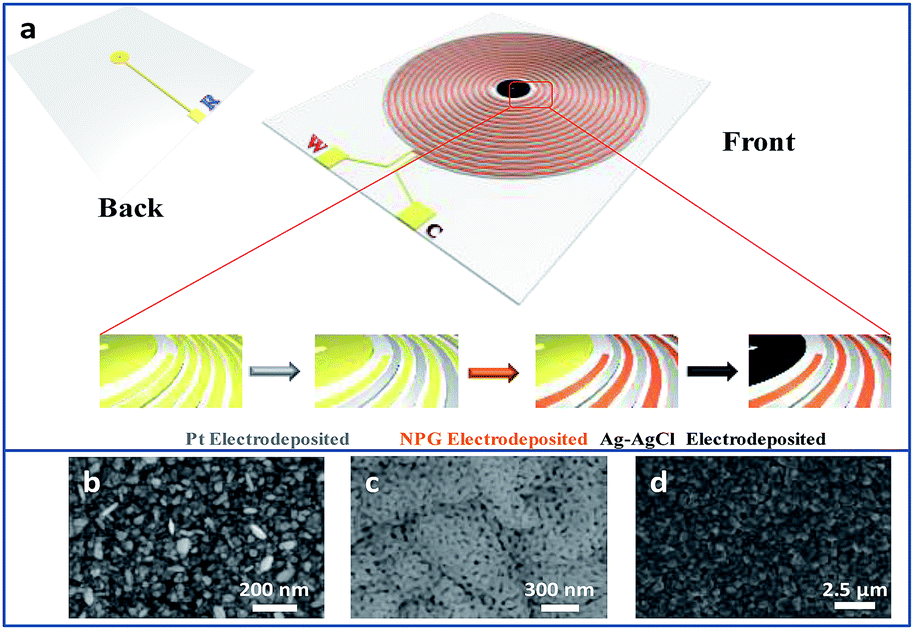
As shown in Fig. 1a, there is a disk in the centre of the interdigitated device. A hole was drilled on the disk, connecting the circuits from front and back sides of the device through sputtering gold so that the disk can be conducted. The interdigitated device modified with Pt and NPG was immersed into the plating solution that contained 40 g L−1 AgNO3, 200 g L−1 Na2S2O3·5H2O, 40 g L−1 K2S2O5, 20 g L−1 NH4Ac and 0.6 g L−1 CH5N3S. A constant current density of 0.3 A dm−2 was applied to electrodeposit Ag on the disk for 15 min. The interdigitated device was rinsed with deionized water and then the disk was dipped in an aqueous solution of 0.1 M KCl and 0.01 M HCl. The potential was swept from −0.15 to 1.05 V versus a commercial Ag/AgCl electrode for five segments at a scan rate of 50 mV s−1 to obtain the final Ag/AgCl electrode on the TEIDGS.
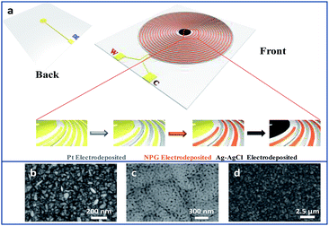 |
| | Fig. 1 (a) The scheme and fabrication process of the TEIDGS and the corresponding morphology, (b), (c) and (d), of the three electrodes. | |
2.5 Material characterization
The surface morphology and element composition of all the samples were characterized by a scanning electron microscope (SEM; Hitachi S-4800) equipped with energy dispersive X-ray (EDX) element mapping. Transmission electron microscopy (TEM; FEI Tecnai G2 F30) was used to analyse the morphology and structure. X-ray diffraction (XRD) measurements were performed on a Rigaku D/max-2200/PC diffractometer using Cu Kα radiation to gain the crystal structure of NPG.
2.6 Electrochemical measurement
All the electrochemical measurements including cyclic voltammetry (CV), chronoamperometry (CA), and electrochemical impedance spectroscopy (EIS) were performed on Gamry REF 600 Electrochemical Workstation. The single NPG electrode was measured in a conventional three-electrode electrochemical cell, with Pt mesh as the counter electrode and Ag/AgCl electrode as the reference electrode. However, the TEIDGS integrated NPG working electrode (WE), Pt counter electrode (CE) and Ag/AgCl reference electrode (RE) can be measured in alkaline solution directly. In a solution of 0.1 M KOH and 0.01 M KCl containing 5 mM glucose, the EIS test has a frequency range of 0.01 Hz to 100 kHz and a potential amplitude of 10 mV at a DC bias of 0.1 V.
3. Result and discussion
3.1 Characteristics of the TEIDGS
Fig. S1† presents the fabrication process of the interdigitated electrode on ceramic circuit board, which can be further processed into sensors. First, a thin film of Ti–W was magnetron-sputtered on an activated alumina ceramic plate. Second, a layer of copper was plated on the Ti–W thin film. Third, the patterns of the interdigitated electrodes were transferred to the ceramic plate by sequentially masking, exposing, etching, and stripping the film. In order to protect the copper wire from oxidative corrosion, a layer of nickel was electrolessly deposited on the Ti–W–Cu interdigitated patterns. Finally, a thin film layer of gold of about 1 μm was electro-deposited on the nickel layer to shield the response signals of nickel and copper and improve the conductivity and electrochemical stability of the device. It can be found that the width of each stripe and the interspace between two adjacent stripes of the interdigitated electrode are both around 100 μm (Fig. S3a†), indicating its high quality. The scheme of the TEIDGS and the corresponding fabrication process are demonstrated in Fig. 1a. The working electrode, counter electrode and reference electrode on the precise ceramic circuit board were designed on the front and back sides, separately. It should be noted that in the middle of the helix working and counter electrodes, the reference electrode is composed of two discs (on the front and back sides of the ceramic circuit board) with a small hollow in its center connecting with each other. The whole fabrication process can be divided into three steps. First, a thin layer of Pt particles was electrodeposited on one of the helix pairs as the counter electrode. Second, the Au–Sn alloy was electrodeposited on another helix pair and then the Sn was dealloyed by soaking in a mixed solution of KOH and H2O2 for an adequate period. Finally, Ag particles were electrodeposited on the reference electrode and then subjected to a CV scan method in a solution containing enough Cl− to form a thin layer of AgCl on its surface, resulting in the final Ag/AgCl reference electrode. The corresponding optical pictures of the different fabrication steps are shown in Fig. S2.† From the SEM images in Fig. 1b–d, it is obvious that NPG owns large quantities of nanopores with an average diameter of 20–50 nm (Fig. 1c). The SEM images of NPG fabricated at different current densities (0.5, 0.8, 1.1 and 1.4 A dm−2) are shown in Fig. S4.† The nano-scale pore size of NPG remained relatively consistent, but the aggregation of large particles was greatly affected by current density. With the increase in current density, more and more large particles were formed on the surface of the electrode, and the flatness was decreased. The aggregation of large particles could result in easier fall off from the substrate and reduce the service life of the electrode. Therefore, the current density in the range of 0.5 to 0.8 A dm−2 was determined as the optimum preparation condition. The Pt nanoparticles on the counter electrode show a rather homogeneous size of 50–100 nm (Fig. 1b) and the Ag/AgCl reference electrode is composed of uniform bulk particles with the size of several microns (Fig. 1d). From the transmission electron microscope (TEM) images in Fig. S5a and b,† it is clear that the nanopores of NPG are evenly distributed and the pore sizes are all between 20-50 nm. It can be found that NPG possesses abundant angularity, as shown in Fig. S5c.† The great catalytic activity of NPG is possibly related to the angular structure at these active positions. The selected area electron diffraction (SAED) pattern of NPG indexed as (111), (200), (220) and (311) planes is shown in Fig. S5d,† suggesting that NPG is polycrystalline. Fig. S6† presents the pore size distributions of NPG. It can be found that nanopores with pore sizes of less than 10 nm occupy nearly 60% of the total specific surface area, while the percentage of specific surface area with pore sizes between 25-40 nm reaches almost 40%. These results are well in accordance with the statistical data originated from SEM and TEM images. The XRD test was further performed to obtain the crystal structure of NPG (Fig. 2a). The result demonstrates that the peaks located at 2θ = 38.2°, 44.3°, 64.5°, 77.5° and 81.7° belong to (111), (200), (220), (311) and (222) crystal planes, respectively, indicating that the synthesized NPG matches well with cubic Au (JCPDS# 04-0784). From the EDS analysis, Au, Cu and Ni were found in the NPG interdigitated electrode, where the Cu and Ni elements belong to the transition layer of the interdigitated planar Au substrate (Fig. 2b). There was no signal of the Sn element, demonstrating that it was completely removed from the original Au–Sn alloy.
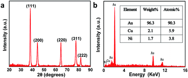 |
| | Fig. 2 (a) XRD pattern and (b) EDS of the NPG. | |
3.2 The electrochemical performance of NPG
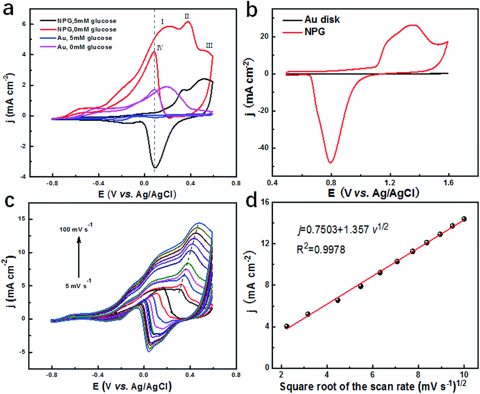
To evaluate the catalytic performance of NPG for glucose, cyclic voltammetry (CV) tests were performed. Fig. 3a presents the CV curves of NPG and the original Au substrate before and after adding 5 mM glucose. It was observed that the Au substrate possessed some catalytic performance since there was an obvious enhancement in current density under the potential of 0.1 V after 5 mM glucose was added, which was due to its mountainous morphology (as shown in Fig. S3b†) with hundreds of nanometres, bringing some active sites for the oxidation of the glucose. Compared with the Au substrate, NPG produced more than two times enhancement in the current density under the potential of 0.1 V, indicating its much better ability in sensing glucose. Four peaks appeared in the CV curve of NPG under 0.1 M KOH. The current density started to increase at the potential of around −0.6 V and the first two peaks appeared at around 0.17 V and 0.33 V. As the potential continued to elevate, more glucose was oxidized and thus the current density increased. After the potential exceeded the third peak at around 0.52 V, Au2O3 was produced and occupied the active sites of the Au(OH)ads, leading to the decline in the current density. When the potential was at a negative going scan, Au2O3 gradually reduced so that the active sites of Au(OH)ads started to increase, resulting in the enhancement of the current density again and the appearance of the fourth peak. CV measurements for NPG in different pH environments were also carried out (Fig. S7†). It was found that the catalytic performances were poor in acidic (pH = 1.00 and 4.00), neutral (pH = 7.00) and weak alkaline (pH = 9.18) conditions. The oxidation of glucose is mainly caused by the hydroxyl radicals (derived from the abundant OH− in the solution) absorbed on the surface of NPG,44,45 which can be described by the following equations (a detailed scheme can be found in Fig. S8†):| | |
Au + OH− → Au(OH)ads + e−
| (1) |
| | |
2Au(OH)ad + C6H12O6 → 2Au + C6H10O6 + 2H2O
| (2) |
 |
| | Fig. 3 (a) CV curves of NPG electrode and gold electrode in 0.1 M KOH and 0.01 M KCl solution with and without 5 mM glucose at a scan rate of 20 mV s−1; (b) CV curves of NPG electrode and planar Au disk electrode in 0.5 M H2SO4 at a scan rate of 100 mV s−1; (c) CV curves of NPG electrode with various scan rates (5, 10, 20, 30, 40, 50, 60, 70, 80, 90, 100 mV s−1) in 0.1 M KOH and 0.01 M KCl solution containing 5 mM glucose; (d) a linear calibration curve represents the relationship between the peak current and square root of the scan rate. | |
Besides, the dissolved oxygen in the electrolyte can be reduced at the Pt counter electrode, as shown in the following equation:
| | |
O2 + 2H2O + 4e− → 4OH−
| (3) |
The overall reaction for the electrocatalytic oxidation of glucose can be expressed by the following equation:
| | |
C6H12O6 + 1/2 O2 → C6H10O6 +H2O
| (4) |
The electrochemical surface areas (ECSA) of NPG and the planar gold disk were then calculated through the CV curves collected in a 0.5 M H2SO4 solution at a scan rate of 100 mV s−1, as shown in Fig. 3b. The ECSA is determined by the integral area of the gold oxide reduction peak, which is proportional to the reactive surface area of the gold surface.46 The much higher ECSA (107.69 cm2) and much larger roughness (215.38) of NPG compared to the planar Au disk (0.12 cm2, 0.24) further verify the superior catalytic performance of the NPG electrode. To clarify which process is in control of the catalytic reaction, CV curves at different scan rates (5–100 mV s−1) were collected in a solution containing 0.1 M KOH, 0.01 M KCl and 5 mM glucose, as shown in Fig. 3c. It can be observed that both peak current and potential increase with the increase in scan rate. As presented in Fig. 3d, the current density j demonstrates a liner relationship with the square root of the scan rate with the correlation coefficient R2 = 0.9978, indicating the diffusion controlled electrochemical behaviour.47 Above results indicate that NPG can be a great choice to detect glucose. Therefore, it is feasible to fabricate three-electrode integrated devices based on the as synthesized NPG and the electrochemical performance of TEIDGS will be further studied.
3.3 The electrochemical performance of the TEIDGS
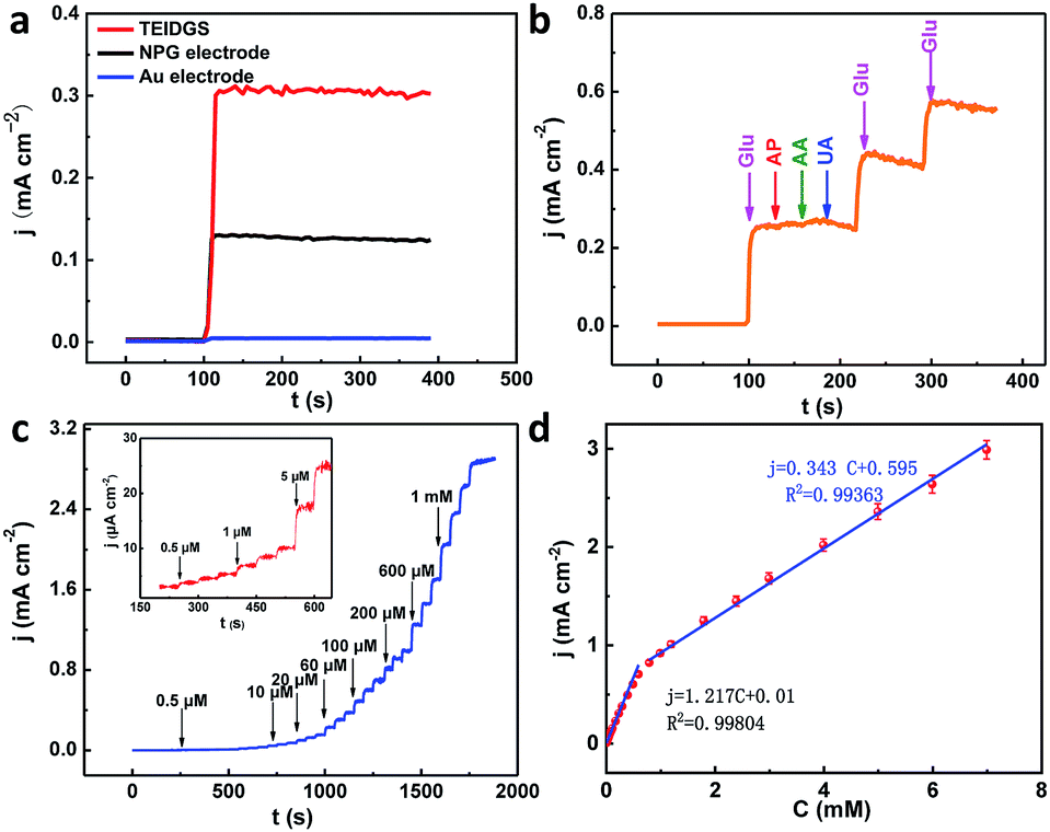
To testify the successful design of our TEIDGS, a series of chronoamperometry measurements were performed to investigate its catalytic performances for glucose. First, the typical j–t curves of the TEIDGS, pure Au electrode and the NPG electrode were collected before and after adding 0.1 mM glucose under an applied voltage of 0.1 V, as shown in Fig. 4a. The TEIDGS based on NPG can produce a current density change of 0.30034 mA cm−2, while the one based on pure Au can only bring a current density change of 0.00355 mA cm−2, presenting around 100 times enhancement in performance. The NPG electrode incorporated with an extra Pt counter electrode and Ag/AgCl reference electrode can only produce a current density change of 0.13187 mA cm−2, which is nearly half of the performance obtained from the TEIDGS. The above results demonstrate that our TEIDGS based on NPG can overcome drawbacks of both the traditional three-electrode configuration and the poor catalytic ability of the planar Au substrate. The selectivity of the TEIDGS was further confirmed by observing the response situation after some common distractors were added, as shown in Fig. 4b. Three interferences including AP, AA and UA were added into the 0.1 M KOH and 0.01 M KCl solution between two separate drops of 0.1 mM glucose. No obvious response current was observed on the addition of these distractors, which confirmed that our TEIDGSs possess perfect selectivity for glucose. The stable step curve with dramatically increased current density following the gradual increase in the concentration of glucose can be found in Fig. 4c. The minimum detection limit reaches as low as 390 nM (S/N = 3, according to the calculation method of IUPAC), which is much lower than most of the gold-based glucose sensors reported previously (Table 1): 50 μM for gold nanowire array,48 10 μM for urchin-like gold submicrostructures,49 8.7 μM for nanoporous gold film,50 and comparable to some researches: 500 nM for nanoporous gold22 and 200 nM for 3D hierarchical porous Au networks.23 Fig. 4d presents the linear relationship between current density and the corresponding glucose concentration. Five parallel samples were tested at the same operational conditions. There are two segments of linear relationship between current density j and the concentration of glucose C: j = 1.217C + 0.010 in the range of 0.001 to 0.590 mM and j = 0.343C + 0.595 in the range of 0.590 to 7.00 mM with correlation![[thin space (1/6-em)]](https://www.rsc.org/images/entities/char_2009.gif) coefficients of 0.99804 and 0.99363, respectively. Thus, the corresponding sensitivities can be as high as 1217 μA mM−1 cm−2 and 343 μA mM−1 cm−2 in the ranges of 0.001–0.590 mM and 0.59–7.00 mM, respectively, demonstrating much superior performance than most gold nanomaterials22,23,49–53 and comparable to gold nanowire arrays48 (309 μA mM−1 cm−2) and gold thin films47 (749 μA mM−1 cm−2). It should be noted that the highest detective limit can reach 7.00 mM, which is enough for practical glucose sensors since the samples to be tested usually need to be diluted firstly. The long-term stability of the TEIDGS was measured through two strategies, as presented in Fig. 5. First, it can retain a stable current response under 0.1 mM glucose solution for over 5000 s with only 8.7% decay (Fig. 5a). Also, the same samples can be kept for nearly three weeks under the same concentration of glucose solution with stable detective performance, as demonstrated in Fig. 5b. Thus, our TEIDGS owns potential in practical applications with stable performance.
coefficients of 0.99804 and 0.99363, respectively. Thus, the corresponding sensitivities can be as high as 1217 μA mM−1 cm−2 and 343 μA mM−1 cm−2 in the ranges of 0.001–0.590 mM and 0.59–7.00 mM, respectively, demonstrating much superior performance than most gold nanomaterials22,23,49–53 and comparable to gold nanowire arrays48 (309 μA mM−1 cm−2) and gold thin films47 (749 μA mM−1 cm−2). It should be noted that the highest detective limit can reach 7.00 mM, which is enough for practical glucose sensors since the samples to be tested usually need to be diluted firstly. The long-term stability of the TEIDGS was measured through two strategies, as presented in Fig. 5. First, it can retain a stable current response under 0.1 mM glucose solution for over 5000 s with only 8.7% decay (Fig. 5a). Also, the same samples can be kept for nearly three weeks under the same concentration of glucose solution with stable detective performance, as demonstrated in Fig. 5b. Thus, our TEIDGS owns potential in practical applications with stable performance.
 |
| | Fig. 4 (a) j–t curves of TEIDGS, NPG electrode and planar Au electrode in 0.1 M KOH and 0.01 M KCl solution with 0.1 mM glucose at a constant potential of 0.1 V. (b) The selectivity towards glucose (0.1 mM) in the presence of AP (10 μM), AA (10 μM) and UA (10 μM) at a constant potential of 0.1 V. (c) Chronoamperometric responses of the three-electrode interdigitated device on the successive addition of glucose in 0.1 M KOH and 0.01 M KCl solution with a constant potential of 0.1 V (inset: the magnified curve for 0.5–6 μM glucose) (d) the calibration curves (current density versus glucose concentration) of the TEIDGS. | |
Table 1 Performance comparison of this work and previous researches based on Au nanomaterials
| Glucose sensor |
Applied potential (V) |
Sensitivity (μA mM−1 cm−2) |
LOD (μM) |
Ref. |
| Nanoporous gold |
0.15 |
24.1, 96.7 |
0.5 |
22 |
| 3D hierarchical porous Au networks |
0.1 |
39.370, 4.362 |
0.2 |
23 |
| Gold thin film |
0.1 |
749.2 |
9.0 |
47 |
| Gold nanowire array |
−0.4 |
309.0 |
50.0 |
48 |
| Urchin-like gold submicrostructures |
0.32 |
16.8 |
10.0 |
49 |
| Nanoporous gold film |
0.2 |
66.0 |
8.7 |
50 |
| Free-standing NPG film |
0.3 |
20.1 |
3.0 |
51 |
| Porous gold cluster film |
0.1 |
10.8 |
1.0 |
52 |
| Dendrite-like gold nanostructures |
0.15 |
190.7 |
50.0 |
53 |
| Three-electrode interdigitated device |
0.1 |
1217.0, 343.0 |
0.39 |
This work |
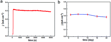 |
| | Fig. 5 Long-term stability tests of the TEIDGS in 0.1 M KOH and 0.01 M KCl solution containing 0.1 mM glucose for (a) over 5000 s and (b) 20 days. | |
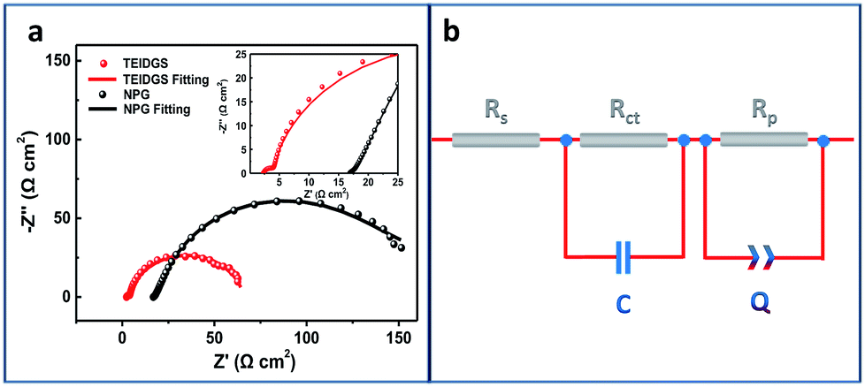
Finally, in order to explore the electron transfer and polarized properties of the TEIDGS, EIS measurements were performed. The EIS of the TEIDGS is composed of two semi-circuits, which represent charge transfer (high frequency region) and the polarized processes, separately. For comparison, the EIS test was also performed on the NPG electrode with outer counter (standard Pt sheet) and reference electrodes (standard Ag/AgCl electrode). As presented in Fig. 6a, both the TEIDGS and NPG electrode own two semi-circuits, which shows the similarity in their transfer character. An equivalent circuit was proposed for representing the EIS results (Fig. 6b), and the fitted values of each element are listed in Table S1.† The TEIDGS possesses a charge transfer resistance (Rct) of 1.516 Ω, representing the fast charge transfer speed of the TEIDGS. Also, the equivalent series resistance (Rs) of the TEIDGS (2.362 Ω) is much smaller than that of the NPG electrode (16.930 Ω), indicating that by using this novel three-electrode structure, the Rs including the ohmic resistance from the electrolyte, the surface and body resistance of the electrode for the TEIDGS can be obviously decreased. Considering the polarized process, a constant phase element (CPE or Q) is adopted. CPE is defined by two parameters, CPE-T and CPE-P. Usually, when CPE-P is 0.5, this element is controlled by the diffusion process (Warburg impedance). If CPE-P is 1 or 0, it represents an ideal capacitor or pure resistor, respectively.54,55 In these two structures, the values of CPE-P for the TEIDGS and NPG electrode are fitted as 0.9018 and 0.5493. Thus, the polarized process of the NPG electrode is closer to the Warburg diffusion, and the TEIDGS is more associated with the capacitive behaviour. Thus, the response process for the oxidation of glucose on the TEIDGS can be more sensitive than on the NPG electrode with outer counter and reference electrodes. It can be also found that the TEIDGS owns a polarized resistance (Rp) of 62.0 Ω, which is smaller than the Rp for the NPG electrode (100.6 Ω). The lower Rp of the TEIDGS can ascribe to the fact that the space between the working electrode and the counter electrode is sufficiently small (100 μm) and overlaps the diffusion layer (0.1–0.001 mm) of the bulk solution region between two electrodes. Therefore, the resistance of the glucose molecule diffusion process (bulk solution → diffusion layer → electrode surface) is reduced, thereby enhancing the response current. In addition, by comparing the EIS data of the TEIDGS, NPG and originally planar Au electrodes (Fig. S9†), it's obvious that the planar Au electrode almost has a diffusion controlled process, which can hinder the redox process greatly and result in the poor catalytic performance for glucose. All of the above confirm that the smart three-electrode design and small space between the working and counter electrodes of the TEIDGS can effectively alleviate the concentration polarization and can be helpful for better charge transfer and a polarized process.
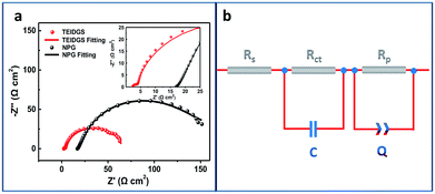 |
| | Fig. 6 (a) Electrochemical impedance spectra (EIS) of the TEIDGS and the single NPG electrode integrated with outer counter and reference electrodes in 0.1 M KOH and 0.01 M KCl solution containing 5 mM glucose and (b) the corresponding equivalent circle. | |
4. Conclusions
Herein, a non-enzymatic three-electrode interdigitated device based on the NPG electrode was successfully designed and fabricated as a high-performance glucose sensor. Three electrodes including NPG as the working electrode, Pt particles as the counter electrode and Ag/AgCl as the reference electrode were integrated into one single ceramic plate circuit. The innovative design of the three-electrode structure and the small space between the working electrode and counter electrode can effectively decrease the concentration polarization of the whole device, thus resulting in smaller electrochemical resistances (Rs, Rct and Rp) and an excellent catalytic ability for glucose. It can achieve a high detective sensitivity for glucose of 1217 μA mM−1 cm−2 and 343 μA mM−1 cm−2 in the ranges of 0.001–0.590 mM and 0.59–7.00 mM, respectively, and a rather low detective limit of 390 nM. In addition, this TEIDGS possesses strong resistance against other interferences, indicating the excellent selectivity. More excitingly, it can be stably operated for nearly three weeks, presenting the potential as a recyclable and long-term glucose sensor. The reasonable design of the three electrodes in a single plane device is easy to be transferred to other substrates such as flexible ones. The novel TEIDGS based on NPG can provide a promising structure design and meaningful material strategy for the future development of glucose sensors.
Conflicts of interest
There are no conflicts to declare.
Acknowledgements
Dr G. Cui and J. Zhao gratefully acknowledge the financial support by the National Natural Science Foundation of China (51271205, 50801070, 51571093), “Project of Science and Technology Plan” by Chinese central authority university fund (2015ZM094, 16lgjc6). This work was also supported by NSFC, China (21622509, 21475122, 21527806), Department of Science and Techniques of Jilin Province (20160201008GX), Jilin Province Development and Reform Commission (2016C014 and 2017C053-1), and Science and Technology Bureau of Changchun (15SS05). We thank Prof. Yexiang Tong and Prof. Guangqin Li from Sun Yat-sen University for their helpful suggestions to this work.
References
- IDF, IDF Diabetes Atlas, 2017, https://www.idf.org/about-diabetes/what-is-diabetes.html Search PubMed.
- A. Heller and B. Feldman, Chem. Rev., 2008, 108, 2482–2505 CrossRef CAS PubMed.
- M. M. Rahman, A. J. Ahammad, J. H. Jin, S. J. Ahn and J. J. Lee, Sensors, 2010, 10, 4855–4886 CrossRef CAS PubMed.
- S. Y. Tee, C. P. Teng and E. Ye, Mater. Sci. Eng., C, 2017, 70, 1018–1030 CrossRef CAS PubMed.
- A. Salek-Maghsoudi, F. Vakhshiteh, R. Torabi, S. Hassani, M. R. Ganjali, P. Norouzi, M. Hosseini and M. Abdollahi, Biosens. Bioelectron., 2018, 99, 122–135 CrossRef CAS.
- S. Park, H. Boo and T. D. Chung, Anal. Chim. Acta, 2006, 556, 46–57 CrossRef CAS.
- N. Muthuchamy, A. Gopalan and K. P. Lee, RSC Adv., 2018, 8, 2138–2147 RSC.
- C. Y. Chen, M. Shi, M. W. Xue and Y. J. Hu, RSC Adv., 2017, 7, 22208–22214 RSC.
- Y. Zhang, Y. Zhang, H. Zhu, S. D. Li, C. Jiang, R. J. Blue and Y. Su, J. Alloys Compd., 2019, 780, 98–106 CrossRef CAS.
- L. Y. Chen, T. Fujita, Y. Ding and M. W. Chen, Adv. Funct. Mater., 2010, 20, 2279–2285 CrossRef CAS.
- X. Y. Lang, H. Y. Fu, C. Hou, G. F. Han, P. Yang, Y. B. Liu and Q. Jiang, Nat. Commun., 2013, 4, 2169 CrossRef.
- K. Tian, M. Prestgard and A. Tiwari, Mater. Sci. Eng., C, 2014, 41, 100–118 CrossRef CAS PubMed.
- X. Luo, M. Huang, L. Bie, D. He, Y. Zhang and P. Jiang, RSC Adv., 2017, 7, 23093–23101 RSC.
- T. N. N. Dau, V. H. Vu, T. T. Cao, V. C. Nguyen, C. T. Ly, D. L. Tran, T. T. N. Pham, N. T. Loc, B. Piro and T. T. Vu, Sens. Actuators, B, 2019, 283, 52–60 CrossRef CAS.
- P. Chakraborty, S. Dhar, K. Debnath, T. Majumder and S. P. Mondal, Sens. Actuators, B, 2019, 283, 776–785 CrossRef CAS.
- H.-H. Li, S. Zhao, M. Gong, C.-H. Cui, D. He, H.-W. Liang, L. Wu and S.-H. Yu, Angew. Chem., 2013, 125, 7620–7624 CrossRef.
- E. Ye, M. D. Regulacio, S. Y. Zhang, X. J. Loh and M. Y. Han, Chem. Soc. Rev., 2015, 44, 6001–6017 RSC.
- S. Nantaphol, T. Watanabe, N. Nomura, W. Siangproh, O. Chailapakul and Y. Einaga, Biosens. Bioelectron., 2017, 98, 76–82 CrossRef CAS PubMed.
- R. Ojani, E. Hasheminejad and J. B. Raoof, Int. J. Hydrogen Energy, 2014, 39, 8194–8203 CrossRef CAS.
- J. Wang, H. Gao, F. Sun and C. Xu, Sens. Actuators, B, 2014, 191, 612–618 CrossRef CAS.
- A. Zhao, Z. Zhang, P. Zhang, S. Xiao, L. Wang, Y. Dong, H. Yuan, P. Li, Y. Sun, X. Jiang and F. Xiao, Anal. Chim. Acta, 2016, 938, 63–71 CrossRef CAS PubMed.
- G.-X. Zhong, W.-X. Zhang, Y.-M. Sun, Y.-Q. Wei, Y. Lei, H.-P. Peng, A.-L. Liu, Y.-Z. Chen and X.-H. Lin, Sens. Actuators, B, 2015, 212, 72–77 CrossRef CAS.
- S. L. Zhong, J. Zhuang, D. P. Yang and D. Tang, Biosens. Bioelectron., 2017, 96, 26–32 CrossRef CAS PubMed.
- X. Xiao, P. Si and E. Magner, Bioelectrochemistry, 2016, 109, 117–126 CrossRef CAS.
- J. Erlebacher, M. J. Aziz, A. Karma, N. Dimitrov and K. Sieradzki, Nature, 2001, 410, 450–453 CrossRef CAS.
- Y. J. Pei, M. Hu, F. H. Tu, X. Y. Tang, W. Huang, S. Chen, Z. L. Li and Y. Xia, Biosens. Bioelectron., 2018, 117, 758–765 CrossRef CAS PubMed.
- J. K. Bhattarai, D. Neupane, B. Nepal, V. Mikhaylov, A. V. Demchenko and K. J. Stine, Nanomaterials, 2018, 8(3), 171 CrossRef.
- J. Zhao, X. Zou, P. Sun and G. Cui, Sci. Rep., 2017, 7, 17857 CrossRef.
- Z. Li, Y. He, X. Ke, L. Gan, J. Zhao, G. Cui and G. Wu, J. Power Sources, 2015, 294, 136–140 CrossRef CAS.
- Y. Xu, X. Ke, C. Yu, S. Liu, J. Zhao, G. Cui, D. Higgins, Z. Chen, Q. Li and G. Wu, Nanotechnology, 2014, 25, 445602 CrossRef PubMed.
- X. Ke, Y. Xu, C. Yu, J. Zhao, G. Cui, D. Higgins, Q. Li and G. Wu, J. Power Sources, 2014, 269, 461–465 CrossRef CAS.
- A. Abellán-Llobregat, I. Jeerapan, A. Bandodkar, L. Vidal, A. Canals, J. Wang and E. Morallón, Biosens. Bioelectron., 2017, 91, 885–891 CrossRef PubMed.
- Y. Chen, S. Lu, S. Zhang, Y. Li, Z. Qu, Y. Chen, B. Lu, X. Wang and X. Feng, Sci. Adv., 2017, 3, e1701629 CrossRef.
- W. Hou, Z. Shi, Y. Guo, X. Sun and X. Wang, Bioprocess Biosyst. Eng., 2017, 40, 1419–1425 CrossRef CAS PubMed.
- C. Jungreuthmayer, G. M. Birnbaumer, P. Ertl and J. Zanghellini, Sens. Actuators, B, 2012, 162, 418–424 CrossRef CAS.
- M. S. Abdul Rahman, S. C. Mukhopadhyay, P.-L. Yu, J. Goicoechea, I. R. Matias, C. P. Gooneratne and J. Kosel, J. Food Eng., 2013, 114, 346–360 CrossRef CAS.
- H. Lee, C. Song, Y. S. Hong, M. S. Kim, H. R. Cho, T. Kang, K. Shin, S. H. Choi, T. Hyeon and D. H. Kim, Sci. Adv., 2017, 3, e1601314 CrossRef PubMed.
- N. Y. Kim, K. K. Adhikari, R. Dhakal, Z. Chuluunbaatar, C. Wang and E. S. Kim, Sci. Rep., 2015, 5, 7807 CrossRef PubMed.
- J. Gui, Y. Zhu, L. Zhang, X. Shu, W. Liu, S. Guo and X. Zhao, Appl. Phys. Lett., 2018, 112, 072902 CrossRef.
- N. Liu and Y. Gao, Small, 2017, 13(45), 1701989 CrossRef.
- D. Pech, M. Brunet, H. Durou, P. Huang, V. Mochalin, Y. Gogotsi, P. L. Taberna and P. Simon, Nat. Nanotechnol., 2010, 5, 651–654 CrossRef CAS PubMed.
- X. Li, L. Luo and R. M. Crooks, Anal. Chem., 2017, 89, 4294–4300 CrossRef CAS.
- S. H. Ko, Y. A. Song, S. J. Kim, M. Kim, J. Han and K. H. Kang, Lab Chip, 2012, 12, 4472–4482 RSC.
- X. Fang, L. Wang, P. K. Shen, G. Cui and C. Bianchini, J. Power Sources, 2010, 195, 1375–1378 CrossRef CAS.
- G. Cui, P. K. Shen, H. Meng, J. Zhao and G. Wu, J. Power Sources, 2011, 196, 6125–6130 CrossRef CAS.
- A. Sukeri, L. P. Saravia and M. Bertotti, Phys. Chem. Chem. Phys., 2015, 17, 28510–28514 RSC.
- C.-W. Hsu, F.-C. Su, P.-Y. Peng, H.-T. Young, S. Liao and G.-J. Wang, Sens. Actuators, B, 2016, 230, 559–565 CrossRef CAS.
- S. Cherevko and C.-H. Chung, Sens. Actuators, B, 2009, 142, 216–223 CrossRef CAS.
- F. Xu, K. Cui, Y. Sun, C. Guo, Z. Liu, Y. Zhang, Y. Shi and Z. Li, Talanta, 2010, 82, 1845–1852 CrossRef CAS.
- Y. Xia, W. Huang, J. Zheng, Z. Niu and Z. Li, Biosens. Bioelectron., 2011, 26, 3555–3561 CrossRef CAS PubMed.
- L. Y. Chen, X. Y. Lang, T. Fujita and M. W. Chen, Scr. Mater., 2011, 65, 17–20 CrossRef CAS.
- L. Han, S. Zhang, L. Han, D.-P. Yang, C. Hou and A. Liu, Electrochim. Acta, 2014, 138, 109–114 CrossRef CAS.
- H. Shu, L. Cao, G. Chang, H. He, Y. Zhang and Y. He, Electrochim. Acta, 2014, 132, 524–532 CrossRef CAS.
- M. E. Orazem and B. Tribollet, Electrochemical Impedance Spectroscopy, John Wiley & Sons, Hoboken, New Jersey, 2008 Search PubMed.
- J. Yang, J. H. Yu, J. Rudi Strickler, W. J. Chang and S. Gunasekaran, Biosens. Bioelectron., 2013, 47, 530–538 CrossRef CAS PubMed.
Footnote |
| † Electronic supplementary information (ESI) available: Fig. S1–S6 and Table S1. See DOI: 10.1039/c8ra10459j |
|
| This journal is © The Royal Society of Chemistry 2019 |
Click here to see how this site uses Cookies. View our privacy policy here. 
 Open Access Article
 This Open Access Article is licensed under a Creative Commons Attribution-Non Commercial 3.0 Unported Licence
 *ab
*ab