
 Open Access Article
 This Open Access Article is licensed under a Creative Commons Attribution-Non Commercial 3.0 Unported Licence
Mechanistic investigation of CO generation by pyrolysis of furan and its main derivatives†
Baizhong Sun,
Honglin Liang ,
Deyong Che,
Hongpeng Liu and
Shuai Guo*
,
Deyong Che,
Hongpeng Liu and
Shuai Guo*
School of Energy and Power Engineering, Northeast Electric Power University, Jilin 132000, China. E-mail: guoshaidq@126.com
First published on 19th March 2019
Abstract
A large amount of furan and its derivatives are contained in the biomass pyrolysis products, which mainly lead to the formation of combustible CO with an increase in the pyrolysis temperature; in this study, to illuminate the reaction mechanisms involved in the evolution of CO during the pyrolysis of furan and its main derivatives, quantum chemical theory has been adopted with the GGA-RPBE method, and nine possible reaction pathways have been investigated for the pyrolysis of furan, furfural (FF), furfuryl alcohol (FA) and 5-hydroxymethylfurfural (5-HMF) to generate CO. According to the calculation results, the optimal path for the pyrolysis of furan and its main derivatives to generate CO is as follows: at first, a ring opening reaction of furan occurs to form an aldehyde group, and then, decarbonylation occurs to form CO. Furthermore, the side chain functional groups on the furan ring can promote the ring opening reaction of the furan ring. In addition, the reaction energy barriers of the rate-determining step for the pyrolysis of furan, furfural, furfuryl alcohol and 5-hydroxymethylfurfural (5-HMF) to form CO have been determined as 343 kJ mol−1, 330 kJ mol−1, 317 kJ mol−1 and 363 kJ mol−1, respectively.
1. Introduction
Due to the growing need to reduce the excessive consumption of fossil energy and the increasing pressure for environmental protection, clean and renewable biomass energy has attracted significant attention. Cellulose is one of the most abundant polymers in nature, accounting for about 50% of biomass, and widely used as a typical biomass for various raw materials to study the distribution of products and the generation of typical products under different reaction conditions.1–3 Furan and its derivatives are the main products of cellulose pyrolysis. Wang et al.1 have studied the pyrolysis products of cellulose using pyrolysis-gas chromatography-mass spectrometry (Py-GC-MS) and found that the proportion of furan and its derivatives in the total product is about 35%, higher than that of small molecular products (SMW) and pyran compounds. Furan and its derivatives mainly include furan, furfural (FF), 5-hydroxymethylfurfural (5-HMF), 2-methylfuran (2-MF), 2,5-dimethylfuran (DMF), furfuryl alcohol (FA), etc. Among them, furan can be used in the synthesis of alkaloids, whereas furfural is mainly used for the preparation of many drugs and industrial products. 2-Methyl furan is an important organic synthesis intermediate in the pharmaceutical industry, and the physical and chemical properties of 2,5-dimethylfuran are very close to those of gasoline.4 Therefore, the pyrolysis of widely available biomass to produce furan and its derivatives is quite promising,5–7 and thus, the exploration of the mechanism of biomass pyrolysis is of significant interest to gain a more in-depth understanding of the formation of furan and its derivatives; furthermore, as one of the main products of biomass pyrolysis,8–10 CO is a relatively clean fuel, and its pyrolysis mechanism has been mainly focused in this research to more deeply understand the decarbonylation of furan and its main derivatives to form CO during biomass pyrolysis.To date, the pyrolysis of furan has been extensively studied experimentally and theoretically. Lifshitz et al.11 studied the pyrolysis of furan molecules via shock tube experiments and proposed two possible monomolecular reaction pathways for the thermal decomposition of furan: (1) CH3C![[triple bond, length as m-dash]](https://www.rsc.org/images/entities/char_e002.gif) CH + CO and (2) HCCH + H2C
CH + CO and (2) HCCH + H2C![[double bond, length as m-dash]](https://www.rsc.org/images/entities/char_e001.gif) CO. The main decomposition products identified are methyl acetylene (C3H4), carbon monoxide (CO) and acetylene (HCCH). These results are in agreement with the experimental results of furan pyrolysis carried out afterwards in a shock tube by Fulle et al.12 On the basis of the experimental results, Sendt et al.13 conducted ab initio calculations at the CASSCF, CASPT2 and G2-(MP2) levels of theory to calculate the two possible monomolecular reaction pathways and obtained many thermochemical and rate parameters for the key reactions. The calculations show that two parallel processes are caused by the following process: 1,2-H transfer leads to the formation of cyclic carbene intermediates and the carbene intermediates are subsequently decomposed into CO + propyne and C2H2 + ketene (as the primary and secondary pathways, respectively), which are the main pathways of furan decomposition. In this case, the energy barrier of the direct ring opening of furan to form CO and propyne was 426 kJ mol−1, and the energy barrier of CO formation by the rupture of the β-carbene structure was 288 kJ mol−1. In 2009, Vasiliou et al.14 studied the thermal decomposition of furan in a tubular silicon carbide reactor and detected free radicals and other substances generated during the reaction process using more advanced techniques such as vacuum ultraviolet photoionization mass spectrometry (PIMS) and matrix isolation infrared spectrometry (IR); moreover, the initial reaction products of furan pyrolysis were determined; the results compensated for the lack of free radical detection in the early experiments and verified Sendt's theoretical calculation (results obtained from the G2(MP2) calculations) conducted 9 years ago. Tranter15 experimentally studied the dissociation of 2-methylfuran at high temperatures using laser schlieren densitometry and theoretically identified many reaction pathways, most of which were initiated by the formation of a carbene.
CO. The main decomposition products identified are methyl acetylene (C3H4), carbon monoxide (CO) and acetylene (HCCH). These results are in agreement with the experimental results of furan pyrolysis carried out afterwards in a shock tube by Fulle et al.12 On the basis of the experimental results, Sendt et al.13 conducted ab initio calculations at the CASSCF, CASPT2 and G2-(MP2) levels of theory to calculate the two possible monomolecular reaction pathways and obtained many thermochemical and rate parameters for the key reactions. The calculations show that two parallel processes are caused by the following process: 1,2-H transfer leads to the formation of cyclic carbene intermediates and the carbene intermediates are subsequently decomposed into CO + propyne and C2H2 + ketene (as the primary and secondary pathways, respectively), which are the main pathways of furan decomposition. In this case, the energy barrier of the direct ring opening of furan to form CO and propyne was 426 kJ mol−1, and the energy barrier of CO formation by the rupture of the β-carbene structure was 288 kJ mol−1. In 2009, Vasiliou et al.14 studied the thermal decomposition of furan in a tubular silicon carbide reactor and detected free radicals and other substances generated during the reaction process using more advanced techniques such as vacuum ultraviolet photoionization mass spectrometry (PIMS) and matrix isolation infrared spectrometry (IR); moreover, the initial reaction products of furan pyrolysis were determined; the results compensated for the lack of free radical detection in the early experiments and verified Sendt's theoretical calculation (results obtained from the G2(MP2) calculations) conducted 9 years ago. Tranter15 experimentally studied the dissociation of 2-methylfuran at high temperatures using laser schlieren densitometry and theoretically identified many reaction pathways, most of which were initiated by the formation of a carbene.
Based on the experimental and theoretical studies on furan, some researchers have carried out further research on furan compounds. Ma et al.16 studied the process of furfuryl alcohol ring-opening and conversion to 1,2-pentanediol via platinum catalysis and verified the calculated results of the density functional theory by the isotopic tracer method. The results show that water molecules can obviously promote the ring opening of furfuryl alcohol. Somers et al.17 performed the calculations for the pyrolysis of 2-methylfuran via the quantum chemical method (CBS-QB3, CBS-APNO and G3). The results showed that the monomolecular decomposition of 2-methylfuran was carried out through the transfer reaction of hydrogen atoms to form a monolinear carbene intermediate. Then, the ring of the monolinear carbene intermediate opened to form a stable non-cyclic C5H6O isomer, which further decomposed into a C1–C4 compound. In addition, the dynamic mechanism of simulation obtained by the scholars is in good agreement with the experimental results obtained using a shock tube in the literature. Charoenwiangnuea et al.18 studied the adsorption and decarbonylation of furfural on a H-ZSM-5 molecular sieve by density functional theory (M06-2X/6-31G (d,p)). Fellah19 theoretically studied the process of direct decarbonylation of furfural to furan via surface catalysis using platinum–graphene. The main catalysis mechanism proposed includes six steps: furfural adsorption, H dissociation from the adsorbed furfural, dissociation of the carbon monoxide molecule from the adsorbed complex (or decarbonylation), furan formation, furan desorption, and CO desorption. Here, furfural decarbonylation is the rate-determining step for furan formation. The global activation potential barrier of the catalytic system obtained by the correction of zero energy and thermal energy is 82 kJ mol−1. Huiyan Zhang et al.20 investigated the pyrolysis of furan and its main derivatives (furan, 2-methyl furan, furfural, and furfural) at 1100 °C via Py-GC/MS. The results show that different side chain functional groups on the furan ring lead to different kinds of products and product distributions. Moreover, two possible mechanisms of benzene formation by polymerization after furan pyrolysis were proposed and calculated using B3LYP/6-31G++ (d,p), which were the Diels–Alder reaction mechanism and the acetylene reaction mechanism.
Furan and its derivatives have a higher proportion in the pyrolysis stage (450–700 °C) of cellulose;1 however, when the pyrolysis temperature is increased to 700–800 °C, the proportion of furan and its derivatives sharply decreases, whereas the CO yield markedly increases.21 Accordingly, it can be inferred that furan and its derivative products produce combustible CO gas during pyrolysis, and Vasiliou's high temperature pyrolysis experiment on furan14 and Fanchiang's catalytic fast pyrolysis experiment on furfural22 have confirmed this implication. In this study, four types of reactants were chosen, and the calculation results of furan were consistent with the experimental results reported by Vasiliou et al.14 However, the theoretical calculation results for the other three furan derivatives have not been experimentally verified, and there is a lack of corresponding theoretical studies in the literature.
To theoretically clarify the mechanism of CO formation, furan, furfural, furfuryl alcohol and 5-hydroxymethylfurfural were selected as reactants. Their decarbonylation process was quantified using density functional theory with the GGA-RPBE method. In addition, the effects of side chain groups on the pyrolysis ring opening reaction of furan rings were investigated by kinetic analysis.
2. Computational details
2.1. Calculation parameters
Density functional theory was adopted in this study, which was included in the DMol3 module of the Materials Studio 2017R2 software (Accelrys, USA). The atoms were treated with the all-electron basis sets,23 and the valence electron function was used to describe the valence orbits of the O, C and H atoms by the double numerical polarization (DNP) basis set. The nonlocal exchange energies and correlation energies of the reactants, products and transition states were calculated by the revised Perdew–Burke–Ernzerhof (RPBE) functional24,25 of the generalized gradient approximation (GGA).26 The threshold values of the convergence criteria for energy, force and displacement were set as 1 × 10⁻⁵ hartree (Ha), 0.002 Ha Å−1, and 0.005 Å, respectively. The overall self-consistent-field (SCF) tolerance, integral accuracy standard, and orbit truncation quality standard were set at medium accuracy. The multilevel extension was set to hexadecapole. A Fermi smearing of 0.005 Ha was used to improve the calculation performance.2.2. Transient state calculation
The geometrical structures of all the stationary point structures were fully optimized at the abovementioned levels through an iterative process, in which the coordinates of atoms were adjusted to reach the stationary points of energy in the structures. The as-optimized structures were then used for the calculation of the reactants or products. However, the transition state is defined as a stationary point with highest energy in the reaction coordinate direction, but lowest energy in other directions. This maximum energy involved is called the activation energy, and the structure corresponding to this energy is called the transition state, which is investigated using the linear synchronous transmission and quadratic synchronous transmission (LST/QST)27 and further confirmed by the Nudged-Elastic Band (NEB) algorithm.28 For a specific reaction, the minimum energy path (MEP) may be complex and may contain multiple local minimum values. The highest saddle point in the path should be significantly noted as the overall reaction rate depends on the height of the barrier. The NEB algorithm takes the transition state found by LST/QST as the starting point, further searches for the possible lowest point in the direction of the reactants and products, and then determines the intrinsic reaction coordinate (IRC); this IRC can be used to check whether the transition state is an instantaneous structure connecting the reactants and products and whether there are other structures available with minimum energy in the reaction path.2.3. Verification of the reliability of the established quantum calculation methodology
In this study, the bond dissociation energies (BDE) of the C–O bond and the C–C bond of a series of related model compounds were calculated and then compared with the experimental results to verify the correctness of the selected method. It can be seen that from Table 1 that the calculated values are very close to the experimental values.29| Species | Ecal/kJ mol−1 | Eexp/kJ mol−1 |
|---|---|---|
 |
388 | 384.9 ± 8.4 |
 |
372 | 379.9 ± 6.3 |
 |
419 | 426.8 ± 4.2 |
 |
299 | 313.8 ± 8.4 |
In addition, the bond length parameters in the geometric structures of furan and furfural calculated in this study were compared with the results reported in literature, as shown in Table 2. It can be seen from Table 2 that the relative differences between the structural parameters obtained by calculation in this study and those reported in the literature are within the errors limits of around 1%, and the differences are insignificant. Therefore, based on the comparisons presented in Tables 1 and 2, the calculation methodology selected in this study is reliable for both the geometric optimization and the energy calculation.
| Structure | Bond | Length | Ref. 13 and 30 | Relative error (%) |
|---|---|---|---|---|
| Furan | C1–C2 | 1.369 | 1.356 | 0.96 |
| C2–C3 | 1.439 | 1.440 | 0.07 | |
| C3–C4 | 1.369 | 1.356 | 0.96 | |
| C4–O5 | 1.378 | 1.378 | 0.00 | |
| O5–C1 | 1.378 | 1.378 | 0.00 | |
| Furfural | C1–C2 | 1.377 | 1.374 | 0.22 |
| C2–C3 | 1.426 | 1.419 | 0.49 | |
| C3–C4 | 1.383 | 1.380 | 0.22 | |
| C4–O5 | 1.392 | 1.386 | 0.43 | |
| O5–C1 | 1.365 | 1.357 | 0.59 | |
| C4–C6 | 1.460 | 1.451 | 0.62 | |
| C6–O7 | 1.231 | 1.231 | 0.00 |
3. Results and discussions
3.1. Structural parameter analysis of furan and its main derivatives
To study the reaction mechanism of CO gas generation through pyrolysis of furan and its main derivatives, the following studies have been carried out. At first, geometric optimization and frequency analysis were carried out for all the reactants, products and intermediates involved in the reaction to determine the space configuration corresponding to the lowest energy point (Fig. S1 and Table S2†). The population numbers of all the reactants and some intermediate products were analysed, and the bonding strength was determined according to the population number. Then, the elementary reaction was constructed, and the reactants and products were atom-paired with each other. After this, a linear synchronous transform and a quadratic synchronous transform were used to search the transition state structures, and the frequency analysis of the transition states obtained by the search showed that the transition states were correct when only one imaginary frequency appeared in the infrared spectrum. Finally, the transition states were confirmed by the nudged elastic band (NEB) method. The imaginary frequency of each transition state is shown in Table 3.| Transition state | Frequency | Transition state | Frequency |
|---|---|---|---|
| TS1 | −586.46 | TS2 | −252.58 |
| TS3 | −1045.63 | TS4 | −320.36 |
| TS51 | −377.95 | TS6 | −671.52 |
| TS7 | −1377.75 | TS8 | −1550.43 |
| TS9 | −484.29 | TS10 | −1407.91 |
| TS11 | −625.41 | TS12 | −1379.29 |
| TS13 | −716.5 | TS14 | −1401.50 |
| TS15 | −1570.91 | TS16 | −611.66 |
| TS17 | −1378.94 |
The population numbers30 were obtained through calculation of the distribution of electron charges among atoms of each component. The electron charge distribution in the atom, atomic orbit, and the positions between two atoms can be obtained by the population analysis, which are called atomic population, orbit population, and bond population, respectively. In this study, the Mayer population analysis was adopted to calculate the bond such that to judge the strength of bonding. The structural information and calculation results of furan and its main derivatives are shown in Fig. 1.
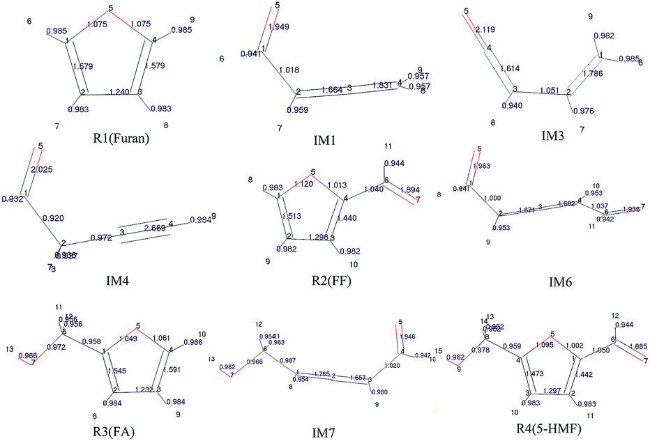 | ||
| Fig. 1 Geometric optimization results and population analysis data for the reactants and intermediates. | ||
It can be seen that the population numbers of C1–O5 and C4–O5 are very small in the furan carbon skeleton; thus, bond breaking and ring opening are most likely at these two places. Overall, the population number of C–H bonds is smallest, through which the following conclusions can be drawn: (1) H atoms are more likely to break away in the reaction, and different transfer positions result in different reaction paths. For example, as for Path 1–3, the ring-opening positions are between C4 and O5. However, when H8 is transferred to C4, the corresponding path is Path 1; when H6 is transferred to C4, the corresponding path is Path 2; and when H8 is transferred to C2, the corresponding path is Path 3. (2) The H transfer process is easier than the ring-opening process; thus, the H transfer process may occur earlier than the ring-opening process. This can be verified from the points mentioned in other studies.31 That is, the pyrolysis of furan first forms an α-carbene structure or a β-carbene structure, flowing which the ring opens; or H in the carbene structures break away first to form the free radical structures, and then, the rings open. According to the population numbers of the three possible intermediates IM1, IM2, and IM3 generated after the R1 ring opening, the population numbers between O5 and C1 are on average larger than those between C1 and C2. The results show that carbon and oxygen form double bonds after ring opening, and the increased bond strength is very likely to result in decarbonylation reactions to generate CO in the subsequent reactions.
To study the effect of the side chain functional group on the furan ring structures, the population numbers of furfural, furfuryl alcohol and 5-hydroxymethylfurfural were calculated. Compared with the case of furfural, it can be found that the population number of the furan ring changes obviously when an aldehyde group is added to the C4 position. Compared with the original furan ring, the population number of C1–O5 increases by 0.045 and that of C4–O5 decreases by 0.062 when the side chain aldehyde is added; this shows that the existence of the side chain makes the C–O bond connected to C become weak and easy to open. Furthermore, on the basis of furfural, by continuing to add a hydroxymethyl side chain at the C1 position, the population number of the C–O bonds in the furan ring becomes smaller. Moreover, the C4–O5 bond population attached to the aldehyde group continues to become smaller from the original 1.013 to 1.002. Therefore, the more the side chain functional groups in the furan ring, the more easily the ring opening reaction occurs.
3.2. Furan pyrolysis
Based on the research reported by Erdmann et al.,31 using the new modified function, three possible paths for furan pyrolysis via ring opening to generate CO were calculated and are presented in Fig. 2. Furthermore, according to the abovementioned pyrolysis path of furan and the population numbers of these reactants, the pyrolysis paths of furfural, furfuryl alcohol and 5-hydroxymethylfurfural to generate CO are presented in the Paths 4–9, which have been be analysed in more detail hereinafter.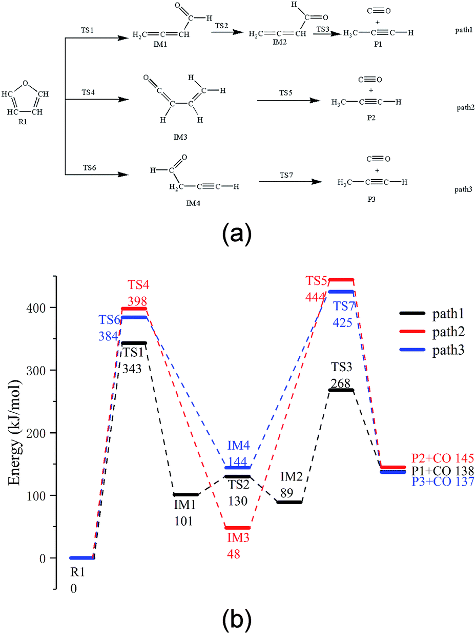 | ||
| Fig. 2 (a) Reaction path of furan pyrolysis and (b) its potential energy profiles. | ||
As shown in Fig. 2a, among the three possible paths of furan pyrolysis, Path 1 shows that the bond of C5–O4 breaks first, and then, H8 moves to the C4 position to generate IM1 with a cumulated diene structure. Since IM1 has a cis-structure, the energy of IM2 with a trans-structure is lower; as shown in the calculation results, the energy of the cis-structure is higher than that of the trans-structure by 12 kJ mol−1, and the energy barrier is 29 kJ mol−1. Since the cumulated diene structure in IM2 is unstable, it can be easily converted to alkynes at high temperatures. Therefore, when the aldehyde decarbonization reaction occurs in IM2, the generation of alkynes and the transfer of H6 to C4 also occur. As shown in Path 2, the C5–O4 bond breaks first; then, H6 transfers to the C4 position, and finally, the C1–C2 bond breaks to generate CO and propyne. As shown in Path 3, the C5–O4 bond breaks first, and then, H8 moves to the C2 position to generate the intermediate IM4; after this, C1–C2 in IM4 breaks to generate CO and propyne.
Via comparing the energy barriers of all the elementary reactions in the three steps, as shown in Fig. 2b, it can be seen that the rate-determining step in the three reaction paths is the ring-opening reaction of furan, and the energy barriers are 343 kJ mol−1, 384 kJ mol−1, and 398 kJ mol−1, respectively. Moreover, in the final step of CO generation by decarbonylation, the energy barrier of Path 1 is 179 kJ mol−1, which is much lower than 396 kJ mol−1 in Path 2 and 282 kJ mol−1 in Path 3. Therefore, Path 1 is the most competitive path among the abovementioned three reaction paths.
3.3. Furfural pyrolysis
There are three possible pathways for the thermal decarbonylation of furfural, corresponding to Path 4 to 6, as shown in Fig. 3. Among these pathways, Path 4 shows the process of removal of the side chain aldehyde within furfural directly, that is, C4–C6 breaks, and H11 moves to the C4 position. The energy barrier for this step is 360 kJ mol−1. As shown in Path 5, C1–O5 breaks, and H9 moves to C8 to generate the intermediate IM5. This consists of two carbonyls and a cumulated diene, which is then decarbonized in the aldehyde at the right end of the structure to generate CO + IM1. The rate-determining step of the reaction is a ring-opening reaction, and the energy barrier of this step is 361 kJ mol−1. The break key of path 6 occurs at the C4–O5 bond position where the furan ring is connected to the side chain. After this, H10 is transferred from C3 to C4. This conclusion is the same as that proposed by Weiming Wan et al.,32 who studied the open-loop reaction of furfural under the action of a catalyst. The rate-determining step of this path is also the ring-opening reaction with an energy barrier of 330 kJ mol−1. Combined with the bond population number of furfural, it can be seen that when the ring is broken to open at C1–O5 where the bond is the strongest, the corresponding reaction barrier is largest; when the bond is broken to open at the weakest C4–O5 position, the energy barrier of the reaction is lowest. The results show that the side chain functional groups have great influence on the thermal decarbonylation of the furan rings; this makes the generation of CO complicated during the whole reaction. Therefore, the generation of CO by Path 4 is also competitive in terms of the reaction steps; this can be supported by the experimental results obtained by Fanchiang et al.22 That is, the proportion of furan and CO in the product of the furfural pyrolysis at 500 °C accounts for 19.5% and 25.1%, respectively. The results indicate that furfural is directly decarbonized to generate furan during the pyrolysis process; however, the content of CO is more than furan. Therefore, it is probable that there are other sources of CO besides the direct decarburization, which may include the two paths proposed in the abovementioned study.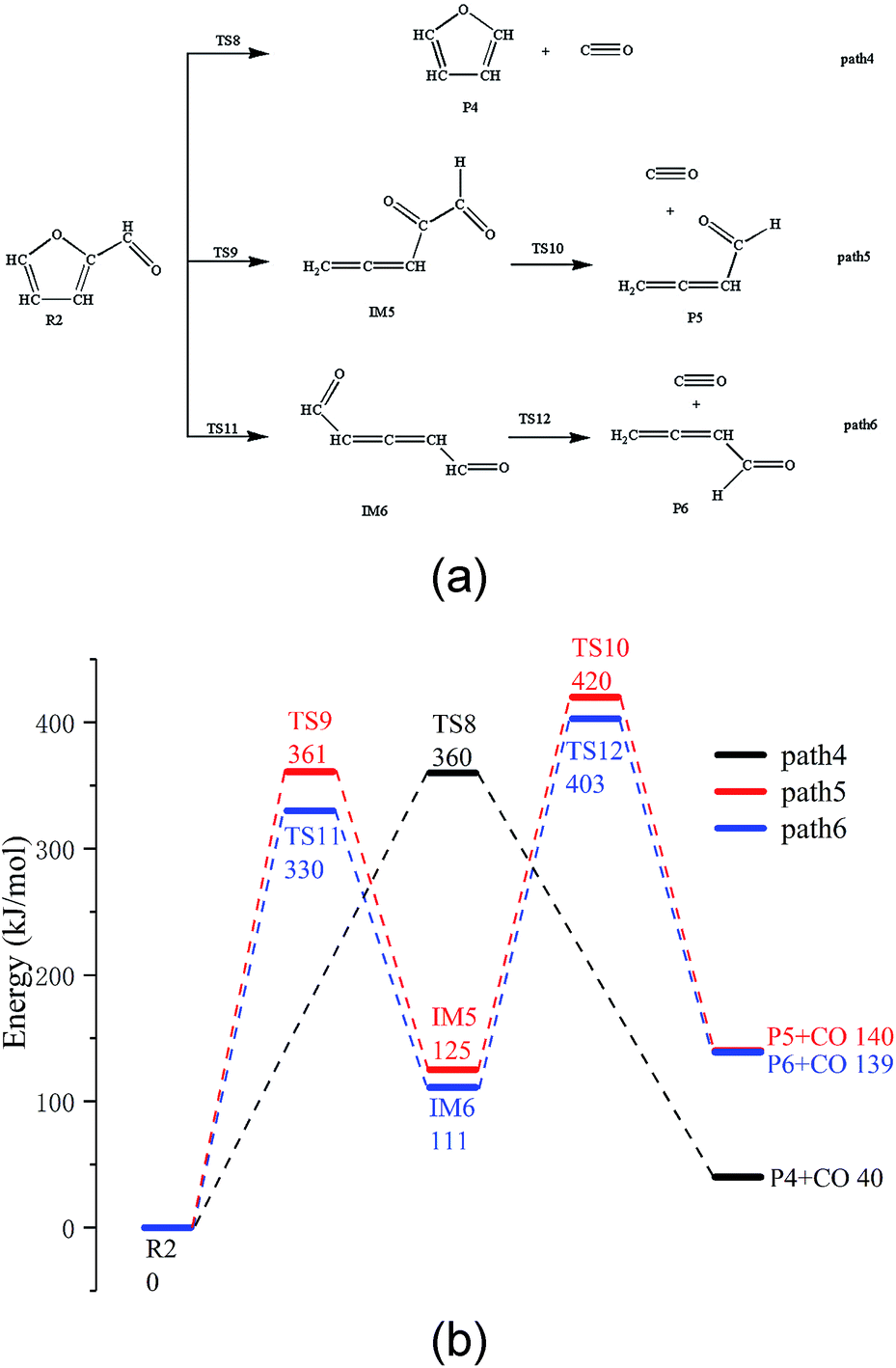 | ||
| Fig. 3 (a) Reaction path of furfural pyrolysis and (b) its potential energy profiles. | ||
3.4. Pyrolysis of furfuryl alcohol and 5-hydroxymethyl furfural
The thermal decarbonylation of FA and 5-HMF is relatively simpler than that of the other furan derivatives as abovementioned. For furfuryl alcohol, there are two ways for generating CO. First, the bond of O5–C1 breaks to form an aldehyde group, which then generates CO by decarbonization. Second, the O5–C4 bond breaks to form a carbonyl group at the position of C1. The bonds of both C1–C6 and C1–C2 break to generate CO from the carbonyl group. Many steps are included in this process, and the bond of O5–C4 is stronger than that of O5–C1 based on the population number analysis, as shown in Fig. 1. Therefore, the most possible way for FA to generate CO is the first path (Path 7, as shown in Fig. 4a). The energy barrier of the furan ring opening in the first step of this path is 317 kJ mol−1, which is lower than the minimum energy barrier of the furan ring opening (343 kJ mol−1). The results show that the side chain in the furan ring decreases the structural stability of the furan ring; thus, it is easier to break. The energy barrier of the intermediate IM7 decarbonylation process in the second step is 307 kJ mol−1, which is larger than the energy barrier of decarbonylation with the similar intermediate IM1(179 kJ mol−1). The results show that when the length of the carbon chain increases, the aldehyde decarbonylation at the end of the carbon chain becomes difficult. | ||
| Fig. 4 (a) Reaction path of FF and 5-HMF pyrolysis and (b) their potential energy profiles. | ||
5-HMF contains two different side chain functional groups, as shown in Fig. 4. FA is generated when the aldehyde group at the C2 position is removed; thus, Path 8 takes into account the process of CO generation by direct decarbonization. The energy barrier of this step is 363 kJ mol−1, and the reaction energy is 43 kJ mol−1, very close to the values of the decarbonylation of the FF side chain aldehyde, which are 360 kJ mol−1 and 40 kJ mol−1, respectively. The results show that the increase in the side chain functional groups in the furan ring does not have much effect on the decarbonylation of the side chain aldehyde group. Moreover, this energy barrier is larger than that of the furan ring opening at 343 kJ mol−1; this indicates that the furan reactants are most likely to undergo a ring opening reaction in the process, instead of the side chain breaking reaction. In addition, in Path 9, where the ring is opened before the generation of CO by decarbonization, the rate determining step is the ring opening reaction, and the corresponding energy barrier is 325 kJ mol−1. The energy barrier of CO generated by this path is much lower than that of the direct decarbonylation in Path 8, which is 363 kJ mol−1.
4. Conclusions
Through theoretical calculations adopting the GGA-RPBE density function, nine possible reaction paths for the reaction mechanism of CO generation by the pyrolysis decarbonylation of furan substances have been proposed in this study. The results are as follows: (1) the optimal path for furan pyrolysis is the breaking of the carbon–oxygen bond to form the cumulated diene structure with the aldehyde group, which then generates CO by decarbonylation. (2) The optimal paths for CO generation by pyrolysis of furfural, furfuryl alcohol and 5-hydroxymethylfurfural include two steps: the breakage of the C–O bond at the junction of the side chain functional groups to form an aldehyde group and then decarbonylation of the aldehyde group on the end chain to generate CO. (3) The existence of the side chain functional groups will reduce the bond energy of C–O in the furan ring and cause the furan ring to more easily open in this position, and thus, the energy barrier of decarbonylation is significantly reduced. Finally, the reaction energy barriers of furan, furfural, furfuryl alcohol and 5-hydroxymethylfurfural in the rate-determining step are determined as 343 kJ mol−1, 330 kJ mol−1, 317 kJ mol−1 and 325 kJ mol−1, respectively.Conflicts of interest
There are no conflicts to declare.Acknowledgements
We gratefully acknowledge the financial support provided by the National Natural Science Funds for Young Scholars of China (Grant No. 51806033), Jilin Provincial Department of Education Research Program (No. JJKH20180434KJ) and Jilin Provincial Science and Technology Development Program (No. 20190201096JC).Notes and references
- S. R. Wang, X. J. Guo, T. Liang, Y. Zhou and Z. Y. Luo, Bioresour. Technol., 2012, 104, 722–728 CrossRef CAS PubMed.
- M. Zheng, Z. Wang, X. Li, X. Qiao, W. Song and L. Guo, Fuel, 2016, 177, 130–141 CrossRef CAS.
- F. Collard and J. Blin, Renewable Sustainable Energy Rev., 2014, 38, 594–608 CrossRef CAS.
- L. Hu, L. Lin and S. Liu, Ind. Eng. Chem. Res., 2014, 53, 9969–9978 CrossRef CAS.
- B. L. F. Chin, S. Yusup, A. Al Shoaibi, P. Kannan, C. Srinivasakannan and S. A. Sulaiman, Energy Convers. Manage., 2014, 87, 746–753 CrossRef CAS.
- X. Zhou, H. B. Mayes, L. J. Broadbelt, M. W. Nolte and B. H. Shanks, AIChE J., 2016, 62, 766–777 CrossRef CAS.
- M. S. Mettler, S. H. Mushrif, A. D. Paulsen, A. D. Javadekar, D. G. Vlachos and P. J. Dauenhauer, Energy Environ. Sci., 2012, 5, 5414–5424 RSC.
- N. Zhao and B. Li, Appl. Energy, 2016, 178, 346–352 CrossRef CAS.
- C. Liu, J. Huang, X. Huang, H. Li and Z. Zhang, Comput. Theor. Chem., 2011, 1–3, 207–212 CrossRef.
- Y. Zhang, H. Lei, Z. Yang, D. Duan, E. Villota and R. Ruan, Green Chem., 2018, 20, 3346–3358 RSC.
- A. Lifshitz, M. Bidani and S. Bidani, J. Phys. Chem., 1986, 21, 5373–5377 CrossRef.
- D. Fulle, A. Dib, J. H. Kiefer, Q. Zhang and J. Yao, J. Phys. Chem. A, 1998, 102, 7480–7486 CrossRef CAS.
- K. Sendt, G. B. Bacskay and J. C. Mackie, J. Phys. Chem. A, 2000, 104, 1861–1875 CrossRef CAS.
- A. Vasiliou, M. R. Nimlos, J. W. Daily and G. B. Ellison, J. Phys. Chem. A, 2009, 113, 8540–8547 CrossRef CAS PubMed.
- R. S. Tranter, P. T. Lynch, J. B. Randazzo, J. P. A. Lockhart, X. Chen and C. F. Goldsmith, Phys. Chem. Chem. Phys., 2018, 20, 10826–10837 RSC.
- R. Ma, X. Wu, T. Tong, Z. Shao, Y. Wang, X. Liu, Q. Xia and X. Gong, ACS Catal., 2016, 7, 333–337 CrossRef.
- K. P. Somers, J. M. Simmie, W. K. Metcalfe and H. J. Curran, Phys. Chem. Chem. Phys., 2014, 16, 5349–5367 RSC.
- P. Charoenwiangnuea, T. Maihom, P. Kongpracha, J. Sirijaraensre and J. Limtrakul, RSC Adv., 2016, 6, 105888–105894 RSC.
- M. F. Fellah, Appl. Surf. Sci., 2017, 405, 395–404 CrossRef CAS.
- S. Wu, H. Yang, H. Jun, H. Zhang and R. Xiao, J. Anal. Appl. Pyrolysis, 2016, 120, 252–257 CrossRef CAS.
- R. Lanza, D. D. Nogare and P. Canu, Ind. Eng. Chem. Res., 2009, 48, 1391–1399 CrossRef CAS.
- W. Fanchiang and Y. Lin, Appl. Catal., A, 2012, 419–420, 102–110 CrossRef CAS.
- B. Delley, J. Chem. Phys., 1990, 92, 508–517 CrossRef CAS.
- B. R. Hammer, Phys. Rev. B, 1998, 11, 7413–7421 Search PubMed.
- B. Delley, J. Chem. Phys., 2000, 113, 7756–7764 CrossRef CAS.
- J. P. Perdew, K. Burke and M. Ernzerhof, Phys. Rev. Lett., 1996, 77, 3865–3868 CrossRef CAS PubMed.
- N. Govind, M. Petersen, G. Fitzgerald, D. King-Smith and J. Andzelm, Comput. Mater. Sci., 2003, 28, 250–258 CrossRef CAS.
- B. J. Berne, Classical and quantum dynamics in condensed phase simulations, World Scientific Publishing Co Pte Ltd, 1998 Search PubMed.
- L. Yuran, Handbook of Bond Dissociation Energies, Science Press, Beijing, 2005 Search PubMed.
- J. Wang, M. Yang, D. Deng and S. Qiu, J. Mol. Model., 2017, 23, 262 CrossRef PubMed.
- E. Erdmann, M. Łabuda, N. F. Aguirre, S. Díaz-Tendero and M. Alcami, J. Phys. Chem. A, 2018, 122, 4153–4166 CrossRef CAS PubMed.
- W. Wan, G. R. Jenness, K. Xiong, D. G. Vlachos and J. G. Chen, Chemcatchem, 2017, 9, 1701–1707 CrossRef CAS.
Footnote |
| † Electronic supplementary information (ESI) available: 3D images of all optimized structures. See DOI: 10.1039/c8ra10106j |
| This journal is © The Royal Society of Chemistry 2019 |