 Open Access Article
Novel crystalline organic–inorganic hybrid silicate material composed of the alternate stacking of semi-layered zeolite and microporous organic layers†
Katsutoshi Yamamoto *a,
Takuji Ikeda
 *b,
Yusuke Tsukamotoa and
Takuma Nakaokaa
aFaculty of Environmental Engineering, The University of Kitakyushu, 1-1 Hibikino, Wakamatsu-ku, Kitakyushu 808-0135, Japan. E-mail: katz@kitakyu-u.ac.jp
bResearch Center for Compact Chemical System, National Institute of Advanced Science and Technology, 4-2-1 Nigatake, Miyagino-ku, Sendai 983-8551, Japan. E-mail: takuji-ikeda@aist.go.jp
First published on 21st January 2019
Abstract
A novel type of crystalline organic–inorganic hybrid microporous silicate material, KCS-5, was synthesized supposedly from a lamellar precursor composed of amphiphilic organosilicic acids. This well-ordered material has a crystalline structure, is thermally stable up to 500 °C and has lipophilic 1-dimensional micropores.
Organic–inorganic hybridization of silicate materials has been diligently studied because it can control surface properties to improve their adsorption capacities and catalytic activities. In these studies, bridged organosilanes, where an organic group connects two trialkoxysilyl species, are frequently employed as a silicon source. For example, Shea et al. prepared microporous amorphous materials named bridged polysilsesquioxanes1 by sol–gel synthesis from various organosilanes with bulky bridging organic groups, such as bis(triethoxysilyl)benzene (BTEB), and Inagaki et al. obtained surfactant-templated hexagonally-ordered mesoporous silicates from organosilanes bridged with aliphatic or aromatic organic groups.2 Tatsumi et al. discovered an improvement in catalytic activities and surface hydrophobicity through the syntheses of a mesoporous titanosilicate3 and zeolites4 from bridged organosilanes. In particular, Bellussi et al. crystallized microporous aluminosilicates called ECS,5 composed of layered aluminosilicate and bridging organic groups. Such bridged organosilanes were used as a single silicon source, presumably because they can theoretically build a three-dimensional silicate framework without introducing structural defects.
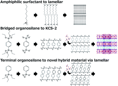
In contrast to bridged organosilanes, terminal organosilanes, where a terminal organic group like a methyl or phenyl group functionalizes trialkoxysilyl species, were not employed as a single silicon source but were subsidiarily added as part of a silicon source because terminal organic groups inevitably cause structural defects which cause a deterioration in the 3-dimensional structure of tectosilicates. However, we conceived an idea to obtain well-ordered materials only from terminal organosilanes inspired by our material KCS-2.6 KCS-2, also synthesized using a bridged organosilane BTEB, is a crystalline organic–inorganic hybrid material with a large 12-ring micropore and unique amphiphilic inner surface properties. Considering that the finely-designed layered structure of KCS-2 is similar to that of a Langmuir–Blodgett membrane, it is deduced that KCS-2 is crystallized via a well-ordered lamellar precursor composed of hydrolysed bridged organosilane (Fig. 1 middle). Because a lamellar structure is formed from amphiphilic surfactant molecules (Fig. 1 top), a well-ordered lamellar precursor should also be formed from amphiphilic organosilicic acid molecules made from terminal organosilanes (Fig. 1 bottom). For example, phenyltriethoxysilane (PTES) was hydrolysed into an amphiphilic molecule with a hydrophilic trihydroxysilyl head group and a hydrophobic phenyl group, which would be self-organized into a lamellar phase. Therefore, through the condensation of silicic acid (with aluminum, if necessary), it would be possible to synthesize a crystalline layered (alumino)silicate.
Actually, we have succeeded in synthesizing a novel crystalline silicate material, KCS-5, from PTES as a single silicon source. In a typical synthesis (please refer to ESI†), a mixture with the molar composition of 1.0 PTES![[thin space (1/6-em)]](https://www.rsc.org/images/entities/char_2009.gif) :
:![[thin space (1/6-em)]](https://www.rsc.org/images/entities/char_2009.gif) 1.0 NaOH
1.0 NaOH![[thin space (1/6-em)]](https://www.rsc.org/images/entities/char_2009.gif) :
:![[thin space (1/6-em)]](https://www.rsc.org/images/entities/char_2009.gif) 5.0H2O was stirred at r.t. for 2–4 days to promote the hydrolysis of PTES to amphiphilic organosilicic acid, which could be arranged into a lamellar-structured precursor. After the addition of fumed alumina powder (Al2O3/Si = 0.2), this mixture was hydrothermally treated at 100 °C for 7 days under static conditions. Generally, KCS-5 was obtained preferentially from mixtures with low H2O/PTES ratios, where the concentration of amphiphilic organosilicic acid was high. In addition, no crystalline products were obtained from this organosilane without the addition of an aluminum source.
5.0H2O was stirred at r.t. for 2–4 days to promote the hydrolysis of PTES to amphiphilic organosilicic acid, which could be arranged into a lamellar-structured precursor. After the addition of fumed alumina powder (Al2O3/Si = 0.2), this mixture was hydrothermally treated at 100 °C for 7 days under static conditions. Generally, KCS-5 was obtained preferentially from mixtures with low H2O/PTES ratios, where the concentration of amphiphilic organosilicic acid was high. In addition, no crystalline products were obtained from this organosilane without the addition of an aluminum source.
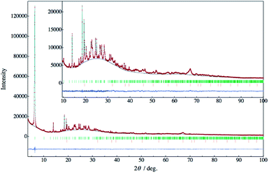
Fig. 2 exhibits the powder X-ray diffraction (PXRD) pattern of KCS-5. A low and wide background ranging from 15° to 40° would be derived from a concomitant amorphous by-product and a borosilicate glass capillary tube. By an indexing analysis, the lattice constant belonging to an orthorhombic system was uniquely found. A crystal structure model of KCS-5 was tentatively built from local structural units, such as SiO4, AlO4 and C6H5–SiO3, elucidated from the solid-state NMR. (The 29Si, 27Al, and 13C solid-state MAS NMR spectra are shown in ESI.†) The packing structure of these units was solved by the direct-space method with the parallel tempering algorithm using the program FOX.7 Table 1 lists the crystallographic information obtained by Rietveld analysis8 using the program RIETAN-FP.9 Reliability factors obtained in this analysis were small enough. The calculated and difference plots obtained by the Rietveld analyses are also exhibited in Fig. 2.
| Compound name | KCS-5 |
| Estimated chemical formula | |Na4·(C2H5OH)0.28|·[Si8Al4O20(C6H5)8] |
| Space group | Pca21 |
| a/nm | 1.12617(2) |
| b/nm | 1.39679(2) |
| c/nm | 0.92161(5) |
| Unit-cell volume/nm3 | 1.44971(4) |
| Z | 4 |
| 2θ Range/° | 3.5–100.1 |
| Step size (2θ)/° | 0.016346 |
| Profile range in FWHM | 12 |
| Number of observations | 5933 |
| Number of contributing reflections | 843 |
| Number of refined structural parameters | 104 |
| Number of constraints | 96 |
![[thin space (1/6-em)]](https://www.rsc.org/images/entities/char_2009.gif) |
|
| R-factors obtained by Rietveld analysis | |
| Rwp | 0.019 |
| RF | 0.011 |
| RBragg | 0.017 |
| Rexp | 0.015 |
| χ2 | 1.62 |
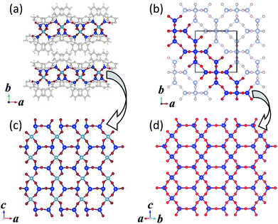
Fig. 3 shows the crystal structures of KCS-5 viewed along the [100] and [001] directions. As can be easily observed, inorganic aluminosilicate layers and organic layers are stacked alternately, tentatively demonstrating the induced formation scheme illustrated in Fig. 1. The structure of the aluminosilicate layer was identical to that of RUB-15![[thin space (1/6-em)]](https://www.rsc.org/images/entities/char_2009.gif) 10 and HUS-1,11 which is isomorphic with the (110) slice part of SOD-type zeolite topology (Fig. 4). Between the aluminosilicate layers two kinds of phenyl groups are observed. The conformation of phenyl groups is of course restricted by the bond angle of the silicon atoms in an aluminosilicate framework and the crystal structure of the aluminosilicate layer; one phenyl group stands almost perpendicularly from the aluminosilicate layer (a–c plane), and the other is inclined at approximately 45° from the a–c plane. Due to these different arrangements of phenyl groups, the organic layer located between the aluminosilicate layers has one-dimensional elliptical pseudo-micropores (Fig. 3 inset). The effective diameter of this micropore is calculated at 6.2 Å × 2.9 Å. The 1D pore shape is strictly zigzag viewed along the b-axis.
10 and HUS-1,11 which is isomorphic with the (110) slice part of SOD-type zeolite topology (Fig. 4). Between the aluminosilicate layers two kinds of phenyl groups are observed. The conformation of phenyl groups is of course restricted by the bond angle of the silicon atoms in an aluminosilicate framework and the crystal structure of the aluminosilicate layer; one phenyl group stands almost perpendicularly from the aluminosilicate layer (a–c plane), and the other is inclined at approximately 45° from the a–c plane. Due to these different arrangements of phenyl groups, the organic layer located between the aluminosilicate layers has one-dimensional elliptical pseudo-micropores (Fig. 3 inset). The effective diameter of this micropore is calculated at 6.2 Å × 2.9 Å. The 1D pore shape is strictly zigzag viewed along the b-axis.
 | ||
| Fig. 3 Crystal structure models of KCS-5 viewed along the [100] (left) and [001] (right) directions. Inset: the magnified drawing clearly shows an elliptical 1-dimensional micropore. | ||
 | ||
| Fig. 4 Crystal structures of (a) KCS-5 and (b) SOD-type zeolites and their component silicate layers (c) and (d), respectively. | ||
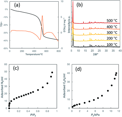
Fig. 5(a) and (b) show the thermogravimetric curve and the PXRD patterns of heat-treated KCS-5, respectively. It can clearly be observed that the crystal structure of KCS-5 is intact under atmospheric conditions until ca. 540 °C when the terminal phenyl groups are burned out. In addition, the stacking structure of KCS-5 was not spoiled by treatment with several solvents such as water, ethanol, toluene or n-hexane (not shown), also demonstrating the high structural stability of KCS-5.
 | ||
| Fig. 5 (a) Thermogravimetric curves of KCS-5, (b) PXRD patterns of heat-treated KCS-5 and adsorption isotherms of KCS-5 for (c) nitrogen and (d) benzene. | ||
The nitrogen adsorption isotherm of KCS-5 (Fig. 5(c)) shows a small adsorption step around P/P0 = 0 to support the presence of the above-mentioned micropores. On the other hand, in the benzene adsorption isotherm (Fig. 5 (d)), a type II isotherm was observed, which indicates good affinity against adsorptive molecules. Although the crystal structural model shows that the micropore opening is large enough to adsorb benzene molecules inside, an obvious adsorption step was not observed near P/P0 = 0. This would be caused by the fact that the size of a benzene molecule and the micropore opening of KCS-5 are very close to each other. In addition, the saturated adsorption volume of benzene is similar to the micropore volume of KCS-5 calculated on the basis of nitrogen adsorption, so the benzene adsorption can be regarded as adsorption inside the micropores. From the experimental results above, KCS-5 with its stable structure and lipophilic inner surface properties would be promising for application to size-selective lipophilic adsorbents.
The synthetic scheme in this study can be applied to other organosilanes with various terminal organic groups, and several crystalline materials have been successfully obtained. These materials are expected to have layered structures providing a lipophilic interlayer space. Therefore, they would stably adsorb or intercalate organic molecules between the silicate layers and might be applicable to host materials having good affinities for organic matter. The structural and physicochemical analyses for these materials are now ongoing, and the results will be reported soon elsewhere.
Conflicts of interest
There are no conflicts to declare.Acknowledgements
This work was supported by JSPS KAKENHI Grant Numbers JP16K14096 and JP16H04569.References
- (a) K. J. Shea, D. A. Loy and O. Webster, J. Am. Chem. Soc., 1992, 114, 6700 CrossRef CAS; (b) D. A. Loy and K. J. Shea, Chem. Rev., 1995, 95, 1431 CrossRef CAS.
- (a) S. Inagaki, S. Guan, Y. Fukushima, T. Ohsuna and O. Terasaki, J. Am. Chem. Soc., 1999, 121, 9611 CrossRef CAS; (b) S. Inagaki, S. Guan, T. Ohsuna and O. Terasaki, Nature, 2002, 416, 304 CrossRef CAS PubMed.
- K. Yamamoto, Y. Nohara and T. Tatsumi, Chem. Lett., 2001, 648 CrossRef CAS.
- (a) K. Yamamoto, Y. Sakata, Y. Nohara, Y. Takahashi and T. Tatsumi, Science, 2003, 300, 470 CrossRef CAS PubMed; (b) K. Yamamoto, Y. Nohara, Y. Domon, Y. Takahashi, Y. Sakata, J. Plévert and T. Tatsumi, Chem. Mater., 2005, 17, 3913 CrossRef CAS; (c) K. Yamamoto and T. Tatsumi, Chem. Mater., 2008, 20, 972 CrossRef CAS.
- (a) G. Bellussi, A. Carati, E. Di Paola, R. Millini, W. O. Parker Jr, C. Rizzo and S. Zanardi, Microporous Mesoporous Mater., 2008, 113, 252 CrossRef CAS; (b) S. Zanardi, W. O. Parker Jr, A. Carati, G. Botti and E. Montanari, Microporous Mesoporous Mater., 2013, 172, 200 CrossRef CAS; (c) G. Bellussi, R. Millini, E. Montanari, A. Carati, C. Rizzo, W. O. Parker Jr, G. Cruciani, A. de Angelis, L. Bonoldi and S. Zanardi, Chem. Commun., 2012, 48, 7356 RSC; (d) G. Bellussi, E. Montanari, E. Di Paola, R. Millini, A. Carati, C. Rizzo, W. O. Parker Jr, M. Gemmi, E. Mugnaioli, U. Kolb and S. Zanardi, Angew. Chem., Int. Ed., 2012, 51, 666 CrossRef CAS PubMed.
- (a) K. Yamamoto, A. Irisa, M. Kawano and T. Ikeda, Chem. Lett., 2014, 43, 376 CrossRef CAS; (b) T. Ikeda, N. Hiyoshi, S. Matsuura, T. Kodaira, T. Nakaoka, A. Irisa, M. Kawano and K. Yamamoto, Angew. Chem., Int. Ed., 2015, 54, 7994 CrossRef CAS PubMed.
- V. Favre-Nicolin and R. Cerny, J. Appl. Crystallogr., 2002, 35, 734 CrossRef CAS.
- H. M. Rietveld, J. Appl. Crystallogr., 1969, 2, 65 CrossRef CAS.
- F. Izumi and K. Momma, Solid State Phenom., 2007, 130, 15 CAS.
- U. Oberhagemann, P. Bayat, B. Marler, H. Gies and J. Rius, Angew. Chem., Int. Ed., 1997, 35, 2869 CrossRef.
- T. Ikeda, Y. Oumi, K. Honda, T. Sano, K. Momma and F. Izumi, Inorg. Chem., 2011, 50, 2294 CrossRef CAS PubMed.
Footnote |
| † Electronic supplementary information (ESI) available: Materials and methods, X-ray crystallographic data in CIF format, and solid-state MAS NMR spectra. See DOI: 10.1039/c8ra09908a |
| This journal is © The Royal Society of Chemistry 2019 |


