
 Open Access Article
 This Open Access Article is licensed under a Creative Commons Attribution-Non Commercial 3.0 Unported Licence
Intact mangrove root electrodes for desalination†
Adam R. Wood a,
Raghav Gargb,
Kyle Justusa,
Tzahi Cohen-Karnibc,
Philip LeDuc*acde and
Alan J. Russell*cdfg
a,
Raghav Gargb,
Kyle Justusa,
Tzahi Cohen-Karnibc,
Philip LeDuc*acde and
Alan J. Russell*cdfg
aDepartment of Mechanical Engineering, Carnegie Mellon University, Pittsburgh, Pennsylvania 15213, USA
bDepartment of Material Science and Engineering, Carnegie Mellon University, Pittsburgh, Pennsylvania 15213, USA
cDepartment of Biomedical Engineering, Carnegie Mellon University, Pittsburgh, Pennsylvania 15213, USA. E-mail: alanrussell@cmu.edu
dDepartment of Biological Sciences, Carnegie Mellon University, Pittsburgh, Pennsylvania 15213, USA
eDepartments Computational Biology, Carnegie Mellon University, Pittsburgh, Pennsylvania 15213, USA
fDepartments of Chemical Engineering & Engineering and Public Policy, Carnegie Mellon University, Pittsburgh, Pennsylvania 15213, USA
gInstitute for Biomedical Materials and Engineering, Northwestern Polytechnical University, Xi'an, China
First published on 11th February 2019
Abstract
Through the benefit of billions of years of evolution, biology has developed tremendous strategies on how to co-exist in high salinity and water scarce environments. Biologically-inspired abiotic systems are becoming a central pillar in how we respond to critical grand challenges that accompany exponential population growth, uncontrolled climate change and the harsh reality that 96.5% of the water on the planet is saltwater. One fascinating biologic adaptation to saltwater is the growth of mangrove trees in brackish swamps and along the coasts. Through a process of salt exclusion, the mangrove maintains a near freshwater flow from roots to leaves to survive. One abiotic approach to water desalination is capacitive deionization, which aims to desalinate low-salinity water sources at energy costs below current technologies, such as reverse osmosis and thermal distillation. In this work, we use one-step carbonization of a plant with developed aerenchyma tissue to enable highly-permeable, freestanding flow-through capacitive deionization electrodes. We show that carbonized aerenchyma from red mangrove roots reduces the resistance to water flow through electrodes by 65-fold relative to carbonized common woody biomass. We then demonstrate the practical use of the intact carbonized red mangrove roots as electrodes in a flow-through capacitive deionization system. These findings have implications in a range of fields including water desalination, bioinspired materials, and plant functionality.
1. Introduction
The ability to desalinate water is a critical area of exploration that will affect populations across the world. One organism that is able to desalinate water already is the mangrove. These plants have developed adaptations to thrive in these high salt environments.1,2 Further enabling the growth of mangroves in high-salinity, flooded and oxygen-deprived environments is the development of aerenchyma tissue in the root. Aerenchyma tissue reduces the risk of asphyxiation by providing a low-resistance pathway for gas transport from the roots to the shoot of the plant.3–6 We hypothesized that the architecture of the mangrove could be used to generate a conductive synthetic aerenchyma mimic that would be an excellent electrode for a flow-through (FT) capacitive deionization (CDI) system.CDI is a low-energy and cost-effective alternative to current desalination technologies for the removal of ionic species from low-salinity water sources. CDI uses electrostatic force to adsorb and store ions from a feed stream to a pair of charged electrodes.7–11 A typical arrangement of the electrodes in a CDI system, termed flow-by (FB), has electrodes that are parallel to the direction of the feed stream. More recently an approach of arranging the electrodes perpendicular to the feed stream, termed FT, has shown promise for faster ion transport and full utilization of the electrode surface.12,13 However, perpendicular FT electrodes typically require high feed pressures to drive water through the micro/meso-sized pores.12,14 This limitation decreases the efficiency of the approach. Effective FT-CDI electrodes would need to combine high salt adsorption capacity (SAC) with low resistance to water flow through the material. One approach to address these interconnected needs involves the fabrication of hierarchical carbon electrodes comprised of both micron-scale and micro/meso-scale pores that function to increase hydraulic permeability while maintaining high SAC.14–17 When considering the need for micron-sized interconnected pores in FT electrodes we were captivated by the idea that if mangrove aerenchyma was conductive, it would be an ideal electrode. We therefore explored to what degree aerenchyma architecture and micro- or nanostructure were retained during carbonization.
Natural resources (i.e. – coconut shells, peanut shells, biochar, leaves) have been used for decades to make porous carbon electrodes by carbonization.18–25 After chemical or physical treatment of raw materials, activated carbons (ACs) exhibit high specific surface area, high electrical conductivity, and are low-cost due to abundancy. Because of these characteristics, ACs are one of the most commonly used materials for a wide range of electrode applications (i.e. – supercapacitors, Li- and Na-batteries, CDI).9,26,27 Remarkably, however, the raw material is almost never used with its intact natural architecture, and is instead crushed and treated to generate a final material. Retaining the microscale structure of an evolutionarily designed, high porosity structure during carbonization was a compelling opportunity to solve some of the vexing challenges of FT-CDI.
The carbonized aerenchyma that we fabricated and integrated into an FT-CDI system presents a new approach to CDI electrode fabrication (Fig. 1). We observed that carbonized red mangrove roots (RMRs) retained the flow characteristics of their living precursors, were conductive enough to perform well as electrodes in a FT-CDI system, and thereby reduced feed concentrations of saltwater by as much as 250 mg L−1 while exhibiting a salt adsorption capacity (SAC) as high as 9.6 mg g−1.
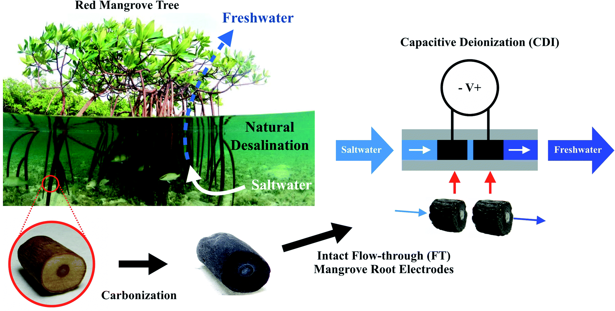 | ||
| Fig. 1 Intact mangrove root electrodes for desalination through flow-through (FT) capacitive deionization (CDI). Using mangroves as an inspiration for desalination, highly permeable FT-CDI electrodes were synthesized in a one-step carbonization process by heating red mangrove roots (RMRs) with developed aerenchyma tissue. The electrodes were then arranged in series through our custom-fabricated silicone coupling and connected to a voltage source via thin graphite rods to form a FT-CDI cell. Upon applying a voltage potential, sodium and chloride ions were adsorbed from the feed stream to the electrode surface resulting in a desalted permeate stream (red mangrove photograph taken by Joost van Uffelen). | ||
2. Results and discussion
2.1 Carbonized mangrove root structure and characteristics
To develop our vision of a biologically derived FT-CDI system we first determined whether carbonization would destroy the low-resistance structure in aerenchyma tissue of the RMR. We used a combination of confocal microscopy and electron microscopy to compare the microstructure before and after carbonization (Fig. 2). We found that, on average, the RMRs retained approximately one third of their dry weight after carbonization with a dramatic retention of microstructure. We imaged the naturally occurring autofluorescence in the tissue of the RMR to observe the structure of the aerenchyma in a fresh, unaltered state. Using our 2D confocal images we generated 3D constructions of the aerenchyma in both the transverse and longitudinal directions (Fig. 2b, c, Movie S1 and S2†). The natural architecture of the aerenchyma was composed of tube-like structures that were extremely well retained after carbonization (Fig. 2e and f). A higher magnification image revealed that there were interconnecting pores in the longitudinal walls of the tubular structures (Fig. S1, ESI†). These structures have been found in the aerenchyma of other mangrove species28,29 and, if retained after carbonization, we hypothesized that they would keep flow resistance low in a FT-CDI system, thus enabling a high-efficiency desalination.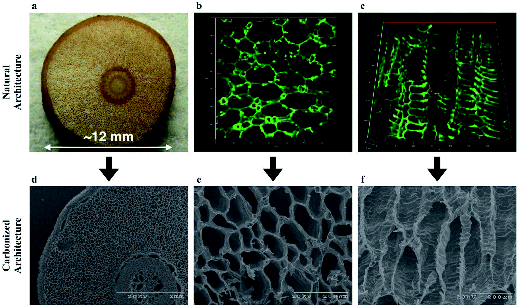 | ||
| Fig. 2 Porous architecture of aerenchyma tissue from RMR for the bioinspired FT-CDI electrodes before and after carbonization. Carbonization was achieved through thermal treatment at 800 °C for 1 hour under argon flow. (a) Digital image of the cross-section of the RMR; (b) confocal image of the autofluorescence of the cross-section for the aerenchyma tissue indicating the porous structures in the tissues; a 3D video of the rendered 3D confocal stack is in Movie S1;† (c) confocal longitudinal image of the autofluorescence for the aerenchyma tissue indicating the repeatable architecture along the length of the tissue; a 3D video of the rendered 3D confocal stack is in Movie S2;† (d) scanning electron microscope (SEM) image of the cross-section of the carbonized RMR indicating the overall structure of the root is maintained through the carbonization process; (e) higher magnification SEM image of the carbonized cross-section for the aerenchyma tissue indicating the porous architecture of the tissue is well-maintained through the carbonization process; (f) SEM longitudinal image of the carbonized aerenchyma tissue indicating the repeatable architecture along the length of the tissue is well-maintained through the carbonization process. | ||
To further understand the structure of our carbonized RMR, we investigated the carbon structure, chemical composition, and specific surface area through Raman spectroscopy (Fig. S2 and Table S1, ESI†), energy-dispersive X-ray (EDX) spectroscopy (Fig. S3 and Table S2, ESI†), and Brunauer–Emmett–Teller (BET) analysis for nitrogen adsorption isotherms (Fig. S4, ESI†). The Raman peaks at 1336 cm−1 and 1585 cm−1 represented the defect (D) and graphitic (G) bands of carbon. The high ID/IG ratio, ranging from 1.05–1.15, indicated that disorder existed in the carbon matrix.30–32 EDX analysis showed high carbon content in the carbonized RMRs with trace amounts of Mg, O, Cl, and Ca. The specific surface area of the carbonized RMRs was between 3 to 216 m2 g−1. Although this range was large, micro/macro-scale features of the harvested aerenchyma (i.e. – cross sectional area of tubular structures) would be expected to vary within the root of the mangrove plant as a function of specific root type, distance from the root apex, and developmental maturity.28,29
2.2 Flow-through characteristics of carbonized mangrove root and common woody biomass
We next compared the structure of the carbonized RMR to other plants which lacked aerenchyma. We carbonized non-specific common woody biomass from trees that do not grow in high salinity or oxygen deprived environments. Within these trees the secondary xylem occupied most of the cross-section and contained tube-like structures,33 similar to the aerenchyma in RMRs. Detailed microscopic comparisons of the carbonized plant tissues (Fig. 3a and b) revealed that the average cross-sectional area of the tube-like structures in the aerenchyma was approximately 10 times more than that of the secondary xylem (Fig. S5a and b, ESI†). Furthermore, the total cross-sectional area percentage that the tube-like structures occupied, which represents potential permeation area for water flow, was 18% higher in the aerenchyma when compared to the secondary xylem. These points suggested that the aerenchyma would provide less resistance to water flow in comparison to the secondary xylem. To understand this approach further, we predicted the permeability of both structures using a bundle of capillaries model for FT-CDI electrodes.14 The permeability was expressed as:| k = εr2/8τ |
 | ||
| Fig. 3 Hydraulic permeability of water flowing through carbonized RMR and common woody biomass. (a) SEM image of tube-like structures in the carbonized RMR aerenchyma; (b) SEM image of tube-like structures in the carbonized secondary xylem of common woody biomass; (c) Normalized flow velocity through each respective carbonized structure versus applied pressure indicating aerenchyma of carbonized RMR (black diamonds) had approximately 65 times less resistance to water permeation than secondary xylem of carbonized common woody biomass (red diamonds). Mean ± s.e.m., n = 8 (carbonized RMR) and n = 3 (carbonized common woody biomass) independent experiments. | ||
To determine experimentally if the aerenchyma posed less resistance to water flow than the secondary xylem, we measured the flow velocity of water through each carbonized structure at low pressures. The flow velocity through the carbonized RMR was on average 65 times faster when compared to the common woody biomass at similar pressures (Fig. 3c). The large difference in flow resistance between the samples in comparison to the theoretical calculations was likely due to a portion of the tube-like structures in the secondary xylem being closed-cell, where the water could permeate into the structure but not through it. In addition, a portion of the tube-like structures in the aerenchyma may not extend all the way through the carbonized RMR samples. However, interconnecting pores (Fig. S1, ESI†) between the tubes could allow for radial flow, enabling an otherwise closed-cell to conduct water. The average hydraulic permeability of the carbonized RMR (1.13 × 10⁻¹¹ m2) was calculated to be 65-fold greater than that of the common woody biomass (1.66 × 10⁻¹³ m2) and on the same order of magnitude as the highest reported value for flow-through electrodes.14
2.3 Desalination performance of intact mangrove root electrodes in flow-through capacitive deionization system
After demonstrating that the intact carbonized RMR exhibited high flow-through characteristics, our next objective was to characterize their performance as electrodes in a FT-CDI system. We used a flexible, custom-fabricated silicone coupling to maintain the carbonized RMR in series. The coupling fit tightly around the outer diameter of the carbonized RMR and directed water flow through the aerenchyma. To provide power for the desalination, the electrodes were connected to a power supply using 0.3 mm graphite rods, which were pressed through the coupling and brought into contact with the carbonized RMR (Fig. S6, ESI†).The FT-CDI experiments were conducted in single-pass (SP) mode with an initial stopped-flow charging (salt adsorption) phase. The SP mode more closely resembles a CDI application,9 although the CDI cell can also be charged while continuously recycling the feed solution as batch-mode (BM). In FT-CDI experiments the electrodes were initially dry and then a 1200 mg L−1 NaCl solution was pumped through the carbonized RMRs at 0.475 mL min−1 for approximately 15 minutes. The flow was then stopped and a potential of 1.5 V was applied to the carbonized RMRs for 15, 45, or 135 minutes. After the initial stopped-flow charging stage, the stock 1200 mg L−1 NaCl solution was pumped into the FT-CDI cell at 0.475 mL min−1 for 30 minutes while the voltage potential was maintained. The partially desalinated volume in the carbonized RMRs was subsequently displaced and flowed downstream to the conductivity meter. The salt concentration downstream of the FT-CDI cell was 1200 mg L−1 until flow resumed.
The change in salt concentration over time was an important measure of how well our mangrove-inspired CDI system functioned. The sharp decrease in salt concentration at the start of the 30 minute flow phase (Fig. 4a) was the displaced volume from one pair of carbonized RMRs. We tested multiple independently prepared sets of carbonized RMRs to investigate how reproducible the performance was in the FT-CDI system. The total mass of the electrode pairs was 58.3, 70.4, and 83.9 mg. For each pair of electrodes, increasing the stopped-flow charging time enabled the carbonized RMRs to adsorb more salt, which resulted in greater reductions in feed concentration (Fig. 4b). The highest reduction in feed concentration we observed was 250 mg L−1. As flow continued, the salt concentration of the permeate gradually returned to the concentration of the feed solution. Even after a stopped-flow charging time of 15, 45, or 135 minutes and 30 minutes of flow, the carbonized RMRs were still adsorbing salt (the permeate solution did not return to 1200 mg L−1). The extended time to reach a saturated state was most likely due to the large length of, and gap between, the electrodes (the electrodes were approximately 5 and 40 times the length and gap, respectively, of other reported FT-CDI systems12). Surprisingly, although the carbonized RMRs did not reach a saturated state, they still exhibited an average SAC as high as 7 mg g−1 (Fig. 4b) and a maximum observed SAC of 9.6 mg g−1. This SAC is competitive with recently reported FT-CDI electrodes (Table 1) and biomass-based CDI electrodes (Table 2). Furthermore, our intact mangrove root electrodes require far less fabrication material and processing compared to most FT and biomass-based electrodes (Tables 1 and 2).
 | ||
| Fig. 4 Capacitive deionization performance of bioinspired FT-CDI system utilizing carbonized RMR as electrodes that have little resistance to water flow. (a) Representative experiment of salt concentration of permeate from bioinspired FT-CDI system after 15 (black), 45 (blue), and 135 (red) minutes of stopped-flow charging at an applied potential of 1.5 V with carbonized RMR electrodes (net mass = 58.3 mg). The dark grey line is a control with identical system and operation for a stopped-flow charging time of 45 minutes without carbonized RMRs. (b) Increasing stopped-flow charging time enabled larger reductions in salt concentration (mean ± s.e.m., n = 3 independent experiments, *p < 0.05), (c) but tended to reduce the charge efficiency of the bioinspired FT-CDI system. (d) Salt concentration of permeate from bioinspired FT-CDI system during cyclic operation (cycle 1 = orange; cycle 2 = pink; cycle 3 = purple, cycle 4 = light blue; cycle 5 = green). The reduction in salt concentration of the permeate from the FT-CDI cell, Λ and ASAR (Fig. S7, ESI†) noticeably increased after the first cycle. | ||
| Electrode | Fabrication materials | Applied voltage (V) | Electrosorption capacity (mg g−1) |
|---|---|---|---|
| Electrospun porous hierarchical carbon nanofibers17 | Polyvinylpyrrolidone | 1.2 | 7.61 |
| Polyacrylonitrile | |||
| Dimethylformamide | |||
| Carbon dioxide | |||
| N-doped porous carbon34 | Zinc nitrate hexahydrate | 1.4 | 16.63 |
| Cobalt nitrate hexahydrate | |||
| Methanol | |||
| 2-Methylimidazole | |||
| Hydrofluoric acid | |||
| Acetylene black | |||
| Polytetrafluoroethylene | |||
| Graphite paper | |||
| 3D graphitic carbon/SiC35 | Silicon carbide foam | 1.5 | 3.2 |
| Methane | |||
| Activated carbon | |||
| 3D foam-like carbon nanoarchitectures36 | Colloidal silica | 1.4 | 20.9 |
| 3-(Trimethoxysilyl)propylmethacrylate | |||
| Epoxy acrylate resin | |||
| 1,4-Butanediol diglycidyl ether | |||
| Sodium hydroxide | |||
| Polytetrafluoroethylene | |||
| Ethanol | |||
| Graphite substrate | |||
| 3D graphene with hierarchical porous structure16 | Polystyrene nanospheres | 1.2 | 14.7 |
| Ammonium molybdate | |||
| Graphite oxide | |||
| Hydrochloric acid | |||
| Polytetrafluoroethylene | |||
| Carbon black | |||
| Graphite sheet | |||
| Hierarchical carbon aerogel monolith12 | Resorcinol | 1.5 | 10.2 |
| Formaldehyde | |||
| Acetic acid | |||
| Carbon dioxide | |||
| Laser-perforated activated carbon14 | Activated carbon electrodes (PAC MM 203) | 1.0 | 3 |
| Intact mangrove root (this work) | R. mangle root | 1.5 | 9.6 |
| Epoxy resin |
| Biomass | Activation/treatment | Binder/additives | Current collector | Applied voltage (V) | Electrosorption capacity (mg g−1) |
|---|---|---|---|---|---|
| a Electrode only used as anode in CDI system. | |||||
| Citrus peel37 | ZnCl2 | PTFE | Titanium mesh | 1.5 | 10.79, 16.2a |
| KOH | PTFE | Titanium mesh | 1.5 | 8.58 | |
| H3PO4 | PTFE | Titanium mesh | 1.5 | 5.22 | |
| — | PTFE | Titanium mesh | 1.5 | 8.44 | |
| Bacterial-cellulose38 | NH3 | — | — | 1.2 | 17.29 |
| Bacterial-cellulose39 | H3PO4 | — | — | 1.2 | 16.20 |
| Bacterial-cellulose40 | — | — | — | 1.2 | 12.81 |
| Palm shell41 | ZnCl2, CO2 | PVdf, DMAc | — | 1.2 | 3.3 |
| Wheat straw42 | KOH, SiO2 sol | PTFE | Graphite sheet | N/A | 2.67 |
| Silk cocoon43 | — | Acetylene black, PVA | Graphite substrate | 1.2 | 12.02 |
| CO2 | Acetylene black, PVA | Graphite substrate | 1.2 | 16.56 | |
| L. leucocephala wood24 | KOH, CO2 | PVDF | — | 1.0 | 2.1 |
| Coconut shell44 | KOH, CO2 | PVDF | — | 1.0 | 20.91 |
| Woody biomass45 | KOH | Nafion | Carbon cloth | N/A | 5.39 |
| Basswood46 | CO2 | — | — | 1.2 | 5.7 |
| Mangrove root (this work) | — | — | — | 1.5 | 9.6 |
We further examined the performance of the carbonized RMRs in the FT-CDI system by calculating the charge efficiency (Λ), which is the ratio of salt adsorbed to the electric charge that accumulated in the electrode pair. Energy consumption for the CDI process normally decreases with increasing Λ, therefore, values as close to unity (theoretical maximum) are highly desirable.47 Common reported values for Λ range between 0.5 to 0.8.48 We observed an average Λ of 0.62, 0.50, and 0.43 for stopped-flow charging times of 15, 45, and 135 minutes, respectively (Fig. 4c) relative to the end of the 30 minute flow phase. The maximum Λ during the flow-phase was reached at a permeate volume of approximately 6 mL and then decreased thereafter.
CDI systems are continuously cycled through adsorption and desorption phases to produce a desalted solution and brine solution, respectively. Therefore, we also investigated the desalination performance of the carbonized RMRs when operated cyclically. In each cycle the flow was first stopped for 15 minutes and a potential of 1.5 V was applied. Next, flow was initiated at 0.475 mL min−1 while maintaining the applied potential for 15 minutes. Finally, the potential was reduced to 0 V and flow continued for 30 minutes. We observed a sharp decrease in salt concentration as the partially desalinated solution was being displaced from the carbonized RMRs when the flow was initiated (Fig. 4d). Interestingly, the performance of the carbonized RMRs increased after the first cycle. A larger reduction in feed concentration was observed, as well as an increased Λ and average salt adsorption rate (ASAR) (Fig. S7, ESI†). The FT electrode arrangement has been shown to enable a higher ASAR, which allows more desalinated water to be produced in a given time frame.12 The ASAR of the mangrove-based CDI system during cyclic operation ranged between 0.063 to 0.075 mg g−1 min−1, which was not as fast as some FT-CDI systems, but comparable to FB-CDI systems. As previously mentioned, however, the length of, and gap between, the carbonized RMR electrodes were much larger than fully optimized FT-CDI systems and would be expected to decrease the ASAR.12 Lastly, the charging current for each cycle was very consistent (Fig. S8, ESI†) and exhibited a repeatable increase when flow was initiated after the stopped-flow charging phase. Once the applied potential was reduced to 0 V, the current direction reversed (discharge current).
3. Conclusions
In this work, we demonstrated that the intact natural architecture of a biomass can serve as an effective and easily fabricated, low-cost intact FT-CDI electrode. The carbonized RMRs were shown to decrease the feed concentration of a 1200 mg L−1 salt solution by as much as 250 mg L−1 and exhibit a SAC as high as 9.6 mg g−1. We also demonstrated that the properties of the biomass have important implications on the performance of the electrodes. Biological adaptations, such as the development of aerenchyma tissue, improve the hydraulic permeability of the freestanding electrode by almost two orders of magnitude in comparison to common plant structures. Intact carbonized plant materials couple the exquisite designs of nature with the ruggedness of the synthetic world.4. Experimental section
4.1 Plant material and carbonization process
Red mangrove (Rhizophora mangle) plants (∼1 meter tall) were grown indoors (20–25 °C) and provided with 16 g L−1 saltwater every 3–4 days as well as being grown in a 12 hour photoperiod. Common woody biomass samples were collected from non-specific woody trees (i.e. – plants that synthesize wood, also known as the secondary xylem, as their main structural component). RMRs and common woody biomass samples were cut to a length of approximately 7.5–10 mm immediately before carbonization. The carbonization was accomplished through heating the samples to 800 °C for 1 hour under 95–100 cm3 min−1 argon flow at a heating rate of 5 °C min−1 in a Lindberg 54553-VH tube furnace. After carbonization, the samples were rinsed with DI H2O three times and then dried at 80 °C for at least 6 hours. The length and diameter of the RMR samples post-carbonization ranged from 5.5–7.5 mm and 7.0–9.5 mm, respectively. The mass of each sample ranged from 25–45 mg.In preparation for examining the hydraulic permeability and integration into the FT-CDI experiments, the pith (center) of each sample was filled with epoxy to limit water transport to the aerenchyma and the secondary xylem (Fig. S9, ESI†), which represents the bulk of the cross-section for RMRs and common woody biomass, respectively. In preparation for the FT-CDI experiments, approximately 250 mL of DI H2O was delivered through the aerenchyma of the carbonized RMRs to remove residual salts and minerals. After each FT-CDI experiment, 50 mL of DI H2O was delivered through the aerenchyma of the carbonized RMRs. The samples were then dried at 80 °C for at least 6 hours and stored at room temperature until further testing.
4.2 Imaging and cross-sectional pore area analysis
The structure of the aerenchyma tissue was determined by imaging the natural plant autofluorescence using a Zeiss Cell Observer Spinning Disk Confocal Microscope (excitation – 488 nm; emission – 525 nm). Layers of these images were processed and combined together to create 3D image stacks. Post-carbonization images were generated by scanning electron microscopy (SEM) using a Jeol JSM 6400 and Philips XL-30 FEG SEM.Cross-sectional area analysis of the tube-like structures in the aerenchyma of the carbonized RMR and in the secondary xylem of the carbonized common woody biomass samples was done using ImageJ. SEM images were converted to black-and-white images using the automatic thresholding tool in ImageJ. The periphery of each pore was then identified using the particle analysis tool, which calculated the cross-sectional area for each element. Pores that intersected the scale bar or that were cut off at the edge were not considered for analysis.
4.3 Characterization
The specific surface area of the carbonized mangrove root samples was characterized by Brunauer–Emmett–Teller (BET) for nitrogen adsorption isotherms using a Micromeritics Gemini VII Surface and Porosity instrument. Raman spectroscopy was performed by NT-MDT NTEGRA spectra using a laser power of 2.38 mW and 532 nm excitation. The spectra were recorded with an acquisition time of 30 seconds at five separate locations on three independently prepared carbonized RMRs. The ID/IG ratio was calculated using the peak intensity at the D-band and G-band. EDX was performed using a Philips XL-30 FEG SEM. Measurements were conducted at three separate locations on four independently prepared carbonized RMRs.4.4 Hydraulic permeability
Flow velocity through carbonized plant tissue was examined using a water column pressure system (Fig. S10, ESI†). Samples were wrapped in Parafilm and connected to the bottom of a water column using a custom-fabricated silicone coupling. The samples were wrapped in Parafilm to direct the bulk flow of water through the carbonized tissue rather than between the sample and the coupling. The time for the meniscus of the water column to drop 2 cm, which equaled a permeate volume of 1 mL, was recorded and used to calculate the flow rate for six different applied pressures ranging from 0.96–2.04 kPa. The applied pressure was calculated by averaging the pressure head of the water column before and after 1 mL of water permeated through the plant tissue based on:| ΔP = ρg(H − Δh/2) |
| k = (QμL)/(ΔPA) |
4.5 Flow-through capacitive deionization
Flow-through CDI experiments were conducted in single-pass mode with an initial stopped-flow charging phase. Two carbonized RMRs were individually wrapped in Parafilm and arranged in series approximately 1–3 mm apart through a custom-fabricated silicone coupling. The length and diameter of the RMR electrodes ranged from 5.5–7.5 mm and 7.0–9.5 mm, respectively. The carbonized RMRs were connected to a DC power supply (BK Precision Model 1670) through 0.3 mm graphite rods (Fig. S6 and S11, ESI†). Three independently prepared carbonized RMR electrode pairs with a net mass of 58.3, 70.4, and 83.9 mg were tested. In each experiment the FT-CDI cell was initially dry. A 1200 mg L−1 NaCl solution was then delivered through the FT-CDI system for approximately 15 minutes at a flow rate of 0.475 mL min−1. The flow was then stopped for 15, 45, or 135 minutes while a potential of 1.5 V was applied to the FT-CDI cell. After the stopped-flow charging phase, flow was reinitiated for 30 minutes at 0.475 mL min−1 while maintaining the applied voltage potential.The NaCl concentration of the permeate from the FT-CDI cell was calculated using conductivity measurements with a custom-built flow-through system (Fig. S11, ESI†). A calibration curve which related salt concentration to conductivity was generated before and after each experiment by flowing NaCl standards ranging from 800–1300 mg L−1 through the conductivity meter. Salt adsorption was calculated by measuring the area under the curve of the permeate during the 30 minute flow phase with respect to the stock salt concentration of 1200 mg L−1. Fig. S12, Table S3 and S4 (ESI†) are control experiments to determine the accuracy of our measurement and calculation techniques for quantifying the change in salt concentration and total salt adsorption.
The charging current in each experiment was measured using a Fluke 287 multimeter with a sampling frequency of 0.5 Hz. The charge efficiency was calculated according to:
| Λ = (Γ × F)/Σ |
![[thin space (1/6-em)]](https://www.rsc.org/images/entities/char_2009.gif) 485 C mol−1), and Σ is the net charge passed through the CDI circuit from the power supply (C g−1). The net charge was calculated by integrating the charging current with respect to time. The ASAR during cyclic operation was calculated by dividing the SAC measured from the 15 minute flow phase by the total cycle time (60 minutes).
485 C mol−1), and Σ is the net charge passed through the CDI circuit from the power supply (C g−1). The net charge was calculated by integrating the charging current with respect to time. The ASAR during cyclic operation was calculated by dividing the SAC measured from the 15 minute flow phase by the total cycle time (60 minutes).
4.6 Statistical analysis
All statistical analysis was conducted using a two-tailed paired Student's t-test.Conflicts of interest
There are no conflicts to declare.Acknowledgements
The authors would like to especially thank Sneha Shanbhag for her input on the project, William Pingitore for his help with the carbonization setup, Joost van Uffelen for the beautiful picture of the red mangrove, and Joseph Suhan for his help with SEM. The authors would like to acknowledge use of the Materials Characterization Facility at Carnegie Mellon University under grant # MCF-677785. This work was supported in part by the Air Force Office of Scientific Research (FA9550-18-1-0262), Office of Naval Research (N00014-17-1-2566), and Pennsylvania Department of Health (SAP4100077084).References
- P. F. Scholander, Physiol. Plant., 1968, 21, 251–261 CrossRef CAS.
- P. Krishnamurthy, P. A. Jyothi-Prakash, L. Qin, J. He, Q. Lin, C.-S. Loh and P. P. Kumar, Plant, Cell Environ., 2014, 37, 1656–1671 CrossRef CAS PubMed.
- M. B. Jackson and W. Armstrong, Plant Biol., 1999, 1, 274–287 CrossRef CAS.
- T. D. Colmer, Plant, Cell Environ., 2003, 26, 17–36 CrossRef CAS.
- D. E. Evans, New Phytol., 2004, 161, 35–49 CrossRef.
- L. A. C. J. Voesenek, T. D. Colmer, R. Pierik, F. F. Millenaar and A. J. M. Peeters, New Phytol., 2006, 170, 213–226 CrossRef CAS PubMed.
- T. J. Welgemoed and C. F. Schutte, Desalination, 2005, 183, 327–340 CrossRef CAS.
- M. A. Anderson, A. L. Cudero and J. Palma, Electrochim. Acta, 2010, 55, 3845–3856 CrossRef CAS.
- S. Porada, R. Zhao, A. van der Wal, V. Presser and P. M. Biesheuvel, Prog. Mater. Sci., 2013, 58, 1388–1442 CrossRef CAS.
- M. E. Suss, S. Porada, X. Sun, P. M. Biesheuvel, J. Yoon and V. Presser, Energy Environ. Sci., 2015, 8, 2296–2319 RSC.
- B. Jia and W. Zhang, Nanoscale Res. Lett., 2016, 11, 64 CrossRef PubMed.
- M. E. Suss, T. F. Baumann, W. L. Bourcier, C. M. Spadaccini, K. A. Rose, J. G. Santiago and M. Stadermann, Energy Environ. Sci., 2012, 5, 9511–9519 RSC.
- Y. Qu, P. G. Campbell, A. Hemmatifar, J. M. Knipe, C. K. Loeb, J. J. Reidy, M. A. Hubert, M. Stadermann and J. G. Santiago, J. Phys. Chem. B, 2018, 122, 240–249 CrossRef CAS PubMed.
- E. N. Guyes, A. Simanovski and M. E. Suss, RSC Adv., 2017, 7, 21308–21313 RSC.
- T. F. Baumann, M. A. Worsley, T. Y.-J. Han and J. H. Satcher, J. Non-Cryst. Solids, 2008, 354, 3513–3515 CrossRef CAS.
- H. Wang, T. Yan, P. Liu, G. Chen, L. Shi, J. Zhang, Q. Zhong and D. Zhang, J. Mater. Chem. A, 2016, 4, 4908–4919 RSC.
- G. Wang, B. Qian, Y. Wang, Q. Dong, F. Zhan and J. Qiu, New J. Chem., 2016, 40, 3786–3792 RSC.
- A. Jain, V. Aravindan, S. Jayaraman, P. S. Kumar, R. Balasubramanian, S. Ramakrishna, S. Madhavi and M. P. Srinivasan, Sci. Rep., 2013, 3, 3002 CrossRef PubMed.
- J. Ding, H. Wang, Z. Li, K. Cui, D. Karpuzov, X. Tan, A. Kohandehghan and D. Mitlin, Energy Environ. Sci., 2015, 8, 941–955 RSC.
- A. M. Dehkhoda, E. Gyenge and N. Ellis, Biomass Bioenergy, 2016, 87, 107–121 CrossRef CAS.
- M. Biswal, A. Banerjee, M. Deo and S. Ogale, Energy Environ. Sci., 2013, 6, 1249–1259 RSC.
- T. E. Rufford, D. Hulicova-Jurcakova, Z. Zhu and G. Q. Lu, Electrochem. Commun., 2008, 10, 1594–1597 CrossRef CAS.
- L. Wei, M. Sevilla, A. B. Fuertes, R. Mokaya and G. Yushin, Adv. Energy Mater., 2011, 1, 356–361 CrossRef CAS.
- C.-H. Hou, N.-L. Liu and H.-C. Hsi, Chemosphere, 2015, 141, 71–79 CrossRef CAS PubMed.
- Y. Li, S. Xu, X. Wu, J. Yu, Y. Wang, Y.-S. Hu, H. Li, L. Chen and X. Huang, J. Mater. Chem. A, 2015, 3, 71–77 RSC.
- L. Wei and G. Yushin, Nano Energy, 2012, 1, 552–565 CrossRef CAS.
- P. Simon and Y. Gogotsi, Nat. Mater., 2008, 7, 845 CrossRef CAS PubMed.
- H. Purnobasuki and M. Suzuki, J. Plant Res., 2004, 117, 465–472 CrossRef PubMed.
- H. Purnobasuki and M. Suzuki, J. Plant Res., 2005, 118, 285–294 CrossRef PubMed.
- A. C. Ferrari and J. Robertson, Phys. Rev. B: Condens. Matter Mater. Phys., 2000, 61, 14095–14107 CrossRef CAS.
- H. Li, F. Shen, W. Luo, J. Dai, X. Han, Y. Chen, Y. Yao, H. Zhu, K. Fu, E. Hitz and L. Hu, ACS Appl. Mater. Interfaces, 2016, 8, 2204–2210 CrossRef CAS PubMed.
- J. Luo, X. Yao, L. Yang, Y. Han, L. Chen, X. Geng, V. Vattipalli, Q. Dong, W. Fan, D. Wang and H. Zhu, Nano Res., 2017, 10, 4318–4326 CrossRef CAS.
- A. Myburg, S. Lev-Yadun and R. Sederoff, Encyclopedia of Life Sciences: Xylem Structure and Function, John Wiley and Sons Ltd., Chichester, United Kingdom, 2013 Search PubMed.
- Z. Wang, T. Yan, J. Fang, L. Shi and D. Zhang, J. Mater. Chem. A, 2016, 4, 10858–10868 RSC.
- Y. Xue, J. Xie, M. He, M. Liu, W. Ni and Y.-M. Yan, J. Mater. Chem. A, 2018, 6, 19210–19220 RSC.
- H. Duan, T. Yan, Z. An, J. Zhang, L. Shi and D. Zhang, RSC Adv., 2017, 7, 39372–39382 RSC.
- Z. Xie, X. Shang, J. Yan, T. Hussain, P. Nie and J. Liu, Electrochim. Acta, 2018, 290, 666–675 CrossRef CAS.
- G. Zhu, H. Wang, H. Xu and L. Zhang, J. Electroanal. Chem., 2018, 822, 81–88 CrossRef CAS.
- Y. Li, Y. Liu, M. Wang, X. Xu, T. Lu, C. Q. Sun and L. Pan, Carbon, 2018, 130, 377–383 CrossRef CAS.
- Y. Liu, T. Lu, Z. Sun, D. H. C. Chua and L. Pan, J. Mater. Chem. A, 2015, 3, 8693–8700 RSC.
- P.-A. Chen, H.-C. Cheng and H. P. Wang, J. Cleaner Prod., 2018, 174, 927–932 CrossRef CAS.
- G. Quan, H. Wang, F. Zhu and J. Yan, BioResources, 2018, 13, 437–449 CAS.
- L. Zhang, Y. Liu, T. Lu and L. Pan, J. Electroanal. Chem., 2017, 804, 179–184 CrossRef CAS.
- C.-L. Yeh, H.-C. Hsi, K.-C. Li and C.-H. Hou, Desalination, 2015, 367, 60–68 CrossRef CAS.
- A. M. Dehkhoda, N. Ellis and E. Gyenge, Microporous Mesoporous Mater., 2016, 224, 217–228 CrossRef CAS.
- M. Liu, M. Xu, Y. Xue, W. Ni, S. Huo, L. Wu, Z. Yang and Y.-M. Yan, ACS Appl. Mater. Interfaces, 2018, 10, 31260–31270 CrossRef CAS PubMed.
- R. Zhao, P. M. Biesheuvel and A. van der Wal, Energy Environ. Sci., 2012, 5, 9520–9527 RSC.
- T. Kim, J. E. Dykstra, S. Porada, A. van der Wal, J. Yoon and P. M. Biesheuvel, J. Colloid Interface Sci., 2015, 446, 317–326 CrossRef CAS PubMed.
Footnote |
| † Electronic supplementary information (ESI) available. See DOI: 10.1039/c8ra09899a |
| This journal is © The Royal Society of Chemistry 2019 |