
 Open Access Article
 This Open Access Article is licensed under a Creative Commons Attribution-Non Commercial 3.0 Unported Licence
Diameter-definable tubing-microchips for applications in both continuous-flow and TEC-modulated on-chip qPCRs with reaction signal analyzed between different types of Teflon-polymers: PTFE and FEP
Yangyang Jiang†
a,
Guizhu Wu†b,
Yuanming Lia and
Wenming Wu *a
*a
aState Key Laboratory of Applied Optics, Changchun Institute of Optics, Fine Mechanics and Physics, Chinese Academy of Sciences, Changchun, 130033, China. E-mail: wuwm@ciomp.ac.cn
bTianjin Key Laboratory of Environmental Remediation and Pollution Control, College of Environmental Science and Engineering, Nankai University, 38 Tongyan Rd, Tianjin 300350, China
First published on 21st January 2019
Abstract
Recently, the tubing microfluidic system has attracted significant research interest because it waives complicated microfabrication machineries and bonding procedures during the manufacture of microchips; however, due to the limited dimensions in the market, the commercially available micro-tubes are generally fixed in diameters and are unmodifiable in radius; this makes it a challenge to obtain a randomly defined channel-dimension for a tubing microsystem. To solve this problem, herein, we proposed a novel and simple method to obtain a tubing-channel with gradually changed diameter. Both the tensile forces and spectrophotometric properties have been analyzed in this study for systemic characterization; as a proof-of-concept, the inner diameter (ID) of a fluorinated ethylene propylene (FEP) tube has been modified from 0.5 mm to 0.3 mm, and the FEP tube has been further applied to both the thermoelectric (TEC)-modulated on-chip polymerase chain reactions (PCRs) and the continuous flow on-chip PCRs. To the best of our knowledge, this is the first time that an FEP tube with so small ID has been applied to on-chip qPCRs. Based on the comparison with polytetrafluoroethylene (PTFE) regarding the fluorescence signal inside the tube, it can be verified that FEP has much better detection sensitivity than PTFE although these two materials are reckoned to be belonging to the same type of polymer family, generally referred to as Teflon.
1 Introduction
Microfluidics, initially as “micro total analytical systems” (μTAS), always combine the basic operation units including sample preparation, chemical/biological reactions, molecule separation and detection, etc.1–4 It can automatically analyze the whole workflow by integrating the biology, chemistry and medicine-based analyses into a micron-scale chip; contrary to traditional laboratories, microfluidics can deal with large quantities of parallel samples due to much less volume consumption, and the analyses can be dramatically sped up to over ten times and even hundred-fold.5 Moreover, the pollution is much less as compared to that with traditional methods.6 Due to the aforementioned advantages, in recent years, microfluidics has been developed in brand-new research fields including biology,7 chemistry,8 medicine,9 electronics,10 nano-materials,11 etc.The key functional unit of a microfluidic system is the microchip. A number of materials, such as poly methyl methacrylate (PMMA),12 poly(dimethylsiloxane) (PDMS),13 glass,14 silicone and Teflon, can be used to fabricate microfluidic chips based on different manufacturing procedures including photolithography,15–18 soft lithography,17,19–21 computer numeric control (CNC) milling,22 laser processing,23 etc. Through these manufacturing procedures, microchannels can be engraved on substrates. Moreover, by a subsequent bonding step, the microchips can be successfully fabricated for further applications in downstream fields.
Recently, a novel microfabrication method has been developed based on rolling a thin tube to defined geometrical structures. Contrary to previous manufacturing procedures, the advantage of this method is that expensive machinery and complicated microfabrication steps are waived. In addition, no bonding steps are required during microfabrication. As a result, compared to the traditional manufacturing procedures, this method is more accessible to ordinary chemistry/biology labs, which may lack professional fabrication instruments; thus, recently, this microfabrication method has attracted significant research interest.
During the past several years, various types of materials including silicone,24 quartz25 and Teflon26–33 have been applied for the fabrication of tubing microfluidic systems. Although these tubes are commercially available, the shortcoming is that the corresponding microchannel is generally fixed in the market and is unmodifiable; thus, it is impossible to obtain a randomly defined channel diameter. In addition, this technological bottleneck restricts the smallest channel-diameter that the tubing-chip can achieve. For instance, the smallest inner diameters of the commercially available polyvinyl chloride (PVC) tube, silicone tube,24 PTFE tube27–33 and FEP tube26 are 0.3 mm, 0.3 mm, 0.3 mm and 0.5 mm, respectively, which limit the application field of these tubes wherein smaller diameters may be required. To solve the aforementioned challenges, herein, we proposed a novel, but very simple method just by extruding the commercially available tube by hand. Then, a microchannel with a wide range of gradually changed diameter-parameters could be obtained.
Among all types of tubes ever applied for microfluidic applications, Teflon tube is the most widely used because of its excellent performance for corrosion resistance, high pressure and temperature resistance, as well as hydrophobic and oleophobic properties. Thus, we further systemically studied the performance of the elongated Teflon tube for downstream applications. To systemically characterize this method, a tensile test machine was applied to analyze the relationship between the tensile strength and the tubing elongation. There are several types of polymers in the Teflon family, and two types, namely PTFE and FEP, can be easily obtained from the market and have been applied for microfluidic-based quantitative PCRs (qPCRs). The PTFE and FEP tubes have almost the same chemical and physical properties; however, their light-transmission is totally different from each other. Just by the naked eye, it can be easily seen that PTFE is translucent, whereas FEP is highly transparent. This promises that PTFE would be less sensitive than FEP when applied for the detection of fluorescence signals during on-chip processing such as qPCRs. Although in several recent studies, the applications of FEP26 or PTFE27–33 microchannels for on-chip PCRs have been reported, the potential difference between the fluorescence signal sensitivity of PTFE and FEP tubes has not been systemically studied to date.
As aforementioned, a PTFE tube with an ID and an OD of 0.3 mm and 0.6 mm,28 respectively, has been successfully applied for real-time qPCRs. However, the smallest ID and OD of a commercially available FEP tube are 0.5 mm (ref. 26) and 0.9 mm, respectively, which are much bigger than 0.3 mm. To make a realistic comparison between the FEP and PTFE tubes, herein, we applied the aforementioned prolongation-technique to change the ID and OD of the FEP tube from 0.5 mm and 0.9 mm to 0.3 mm and 0.6 mm, respectively. Then, we systemically analyzed the difference in the fluorescence signals for qPCRs inside the PTFE and FEP tubes. To the best of our knowledge, this is the first time that an FEP tube with a very small inner diameter of 0.3 mm has been applied to qPCRs.
Overall, two types of qPCRs were tested inside the PTFE and FEP tubes with same diameter.
One type is the continuous flow on-chip PCRs, wherein the samples continuously flow between the denaturation and annealing temperatures inside the PTFE and FEP tubes. Based on the real-time detection of fluorescence signals, it has been confirmed that the FEP tube has a much higher ratio of signal to background noise than the PTFE tube. As a proof-of-concept, we further utilized a self-activated micropump to replace the syringe pump for sample automation inside a 3D spiral FEP tube (ID = 0.3 mm and OD = 0.6 mm), and the thermal cycle was controlled by a single thermostatic heater; herein, a similar amplification efficiency of PGEM-3ZF(+) between this miniaturized on-chip PCR system and the commercial cycler was proved.
In addition, we designed another type of on-chip qPCRs by injecting the PCR samples into the FEP and PTFE tubes, which were then placed on a TEC-based temperature controller for thermal cycling (Fig. 1). Similar to the case of micro continuous PCRs, it is also confirmed that the FEP tube has a much higher ratio of signal-to-background noise than the PTFE tube. Finally, we compared the real-time signal amplification of the FEP tube, PTFE tube and the commercial qPCR cycler, and it was found that as compared to that of the PTFE tube, the PCR-amplification curve of the FEP tube was much closer to that of the thermal cycler. We believe that our method can greatly broaden the tubing microfluidics for downstream applications.
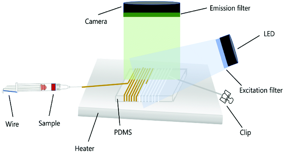 | ||
| Fig. 1 Schematic demonstrating the microdevice wrapped with Teflon polymers. | ||
2 Methods
2.1 Fabrication of the microdevice
Fabrication of the microdevice was the first and most fundamental step in realizing the function of the microfluidic system. Based on the two types of on-chip PCRs studied in this research, overall, two formats of microsystems were fabricated correspondingly. Before system construction, the FEP tube with an ID of 0.5 mm (OD is 0.9 mm or 1.6 mm) was manually prolonged to gain a modified ID of 0.3 mm (OD was changed to 0.6 mm or 1 mm) through a tensile tester with a constant pulling speed. For micro-continuous PCRs, the microreactor was fabricated by wrapping the modified FEP tubes or the commercially available PTFE tubes around the PDMS mold, followed by sequentially connecting one syringe, one fine needle, and the 3D spiral Teflon tube (NAFLONR, ASONE, Shanghai, China) with each other for good sealability. The sample was transported either by a syringe pump (LD-P2020II, Lande, Shanghai, China) or a self-activated micropump wherein an additional silicone tube (NAFLONR, ASONE, Shanghai, China) was connected to the end of the Teflon tube and used as a gas-permeable component for velocity control. For TEC-modulated (Junsi electron, Jiaxing, China) on-chip PCRs, the same volume of fluorescent PCR reagents was added to the four pieces of PTFE and FEP tubes with same length and ID of 50 mm and 0.3 mm, respectively, which were then located on top of the TEC modulator for thermal cycling.2.2 Sample injection for on-chip PCRs
For continuous flow on-chip PCRs, the sample was transported inside the Teflon tube placed on top of the single heater with constant temperature. When the sample was transported by the syringe pump, the mineral oil (M8410, Sigma-Aldrich, MO) was first introduced into the entire channel of the Teflon tube. Then, 20 μL sample was introduced into the PTFE/FEP tube followed by another plug of the mineral oil to form complete encapsulation of the sample plug by the oil phase. The flow of the syringe pump was adjusted to achieve a persistent flow rate, and the samples were obtained from the outlet.When the sample was transported by the self-activated micropump, a 10 cm long hollow silicone tube (ID = 1 mm, OD = 2 mm) was connected to the outlet of the FEP tube, which was then blunt-ended by a clip. Then, the inlet of the Teflon tube was connected to a 27G needle and combined with a disposable syringe (HD, Jiangxi, China). For flow automation, the position of the syringe (containing PCR reagent) was pushed from the initial calibration of 20 mL to 10 mL. The air in the syringe was thus compressed to guarantee a persistent flow rate inside the microchip.
For the TEC (Junsi electron, Jiaxing, China)-modulated on-chip PCRs, the temperatures of the heater periodically changed between the denaturation temperature and annealing temperature. During sample injection, the PCR sample was injected into 35 mm long FEP (ID = 0.3 mm, OD = 0.6 mm) and PTFE tubes (ID = 0.3 mm, OD = 0.6 mm). Then, the two ends of the Teflon tubes were glued (WD1001, Kangda, Shanghai, China) to avoid evaporation during thermal cycling.
2.3 Temperature measurement
An infrared (IR) camera (Fotric 220, ZXF Laboratory, TX) was used for measuring the heater temperatures during the continuous flow on-chip PCRs and the TEC-modulated on-chip PCRs. The height of the PDMS mold was used for controlling the annealing/extension temperatures on the top surface of the PDMS elastomer. Then, ten spots were randomly chosen, and the variable coefficient of temperatures was estimated. The temperature of the TEC module was also monitored during the thermal cycling to guarantee the most proper cycling conditions for efficient target amplification inside the FEP/PTFE tubes.2.4 Reagents
The PCR reagents contained 1X SRBR Premix Ex Taq II, 0.075 U μL−1 TaKaRa EX Taq, 0.6 mg mL−1 BSA (AS25483, AMEKO, China), 1 μM forward and reverse primers, and 107 copies per μL DNA template. Agarose powder (V900510, Sigma-Aldrich, MO) and 0.5X TBE buffer (PH1755, Phygene) were used for agarose gel electrophoresis. The primer sequences for the continuous flow on-chip PCRs were as follows: 5′ ACA GAA TCA GGG GAT AAC GCA GGA AAG AAC A 3′ (forward) and 5′ GTC AGG GGG GCG GAG CCT ATG GAA AAA C 3′ (reverse). The primer sequences for the TEC-modulated on-chip PCRs were as follows: 5′ CCA GTC GGG AAA CCT GTC GTG CC 3′ (forward) and 5′ GTG AGC GAG GAA GCG GAA GAG CG 3′ (reverse). The gene segment of PGEM-3ZF(+) was inserted into the pUC57-Kan plasmid vector (Genewiz, Suzhou, China) by recombinase and further used as the PCR target.2.5 Image acquisition and processing
The fluorescence signal of the PCR reagents was excited by an LED array (XPE60W, Cree, NC) and filtered with a narrow band-pass filter (470 nm, Xintian bori, Beijing, China). The florescence images were obtained by a digital camera (EOS 7D, Canon, Japan) with its lens covered by an emission filter (520 nm, Xintian bori, Beijing, China). The digital camera was set at F 2.8, M 1/5, and ISO∼2000. ImageJ software was used to systematically detect the amplification signals and quantify the fluorescence intensity.2.6 The spectrophotometric analysis and tensile test
Tensile strength was measured by the tensile test machine (JF-100P, Jianfeng Instrument, Dongguan, China). The FEP and PTFE tubes with the same length of 50 mm, but with varied ID and OD were analyzed for all the tensile analyses. The transmittance analyses were conducted by a spectrophotometer (Lambda 950) for scanning the wavelength between 400 nm and 600 nm of the thin PTFE (TS-PTFE FILM, Tongshi, China) and FEP (Saint Gobain, France) plate. A mixture of SYBR Green and DNA template was also injected inside the PTFE and FEP tubes for fluorescence analyses by the ImageJ software. The intensity of the light source was measured by a digital lux meter (AR813A, SMART SENSOR, China).3 Results and discussion
3.1 The tensile test
Teflon tubes of various dimensions were mechanically prolonged to obtain the gradually changed diameters, with the tensile strength accurately measured. As shown in Fig. 2(a–d), the 50 mm long Teflon tubes with different diameters (PTFE, ID 0.3 mm, OD 0.6 mm; PTFE, ID 0.5 mm, OD 0.9 mm; FEP, ID 0.5 mm, OD 1.6 mm; and FEP, ID 0.8 mm, OD 1.6 mm) were first fixed by the tensile device and then pulled with a constant pulling speed (250 mm min−1) until the Teflon tube was broken. As shown in Fig. 2(e), the critical tensile strengths during the prolongation of the Teflon tubes were measured to be 5.8 N, 12.3 N, 35.3 N and 36.4 N respectively for the PTFE tube (ID 0.3 mm, OD 0.6 mm; ID 0.5 mm, OD 0.9 mm) and FEP tube (ID 0.5 mm, OD 1.6 mm; ID 0.8 mm, OD 1.6 mm). Correspondingly, the increased lengths were 637%, 538%, 393% and 395% times of the initial lengths.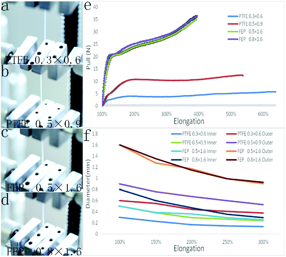 | ||
| Fig. 2 Results of the tensile strength test. (a)–(d) Series of images showing the tensile experiment for different Teflon tubes. (e) The tensile strength of different Teflon tubes with different diameters during the elongation process. (f) The changes of the tubing diameters during the elongation process. | ||
Fig. 2(f) shows the relation between the decreased diameter and increased length during the tensile test. When the tensile ratios were 150%, 200%, 250% and 300%, the inner diameters of the PTFE tubes (ID 0.3 mm, OD 0.6 mm) were decreased to 0.23, 0.17, 0.15, and 0.13 mm, with the outer diameters decreased to 0.55, 0.44, 0.41, and 0.38 mm; on the other hand, the inner diameters of the PTFE tube (ID 0.5 mm, OD 0.9 mm) were decreased to 0.38, 0.30, 0.27, and 0.24 mm, with the outer diameters of the PTFE tubes decreased to 0.76, 0.67, 0.60, and 0.53 mm, respectively. For the FEP tube (ID 0.5 mm, OD 1.6 mm), the inner diameter decreased to 0.39, 0.36, 0.29, and 0.26 mm, whereas the outer diameter decreased to 1.27, 1.172, 0.99, and 0.906 mm when the tensile ratios were 150%, 200%, 250% and 300%, respectively; on the other hand, the inner diameters of the FEP tube (ID 0.8 mm, OD 1.6 mm) decreased to 0.39, 0.36, 0.29, and 0.26 mm, whereas the outer diameters decreased to 1.27, 1.172, 0.99, and 0.906 mm at the same tensile ratios.
3.2 The transmittance results
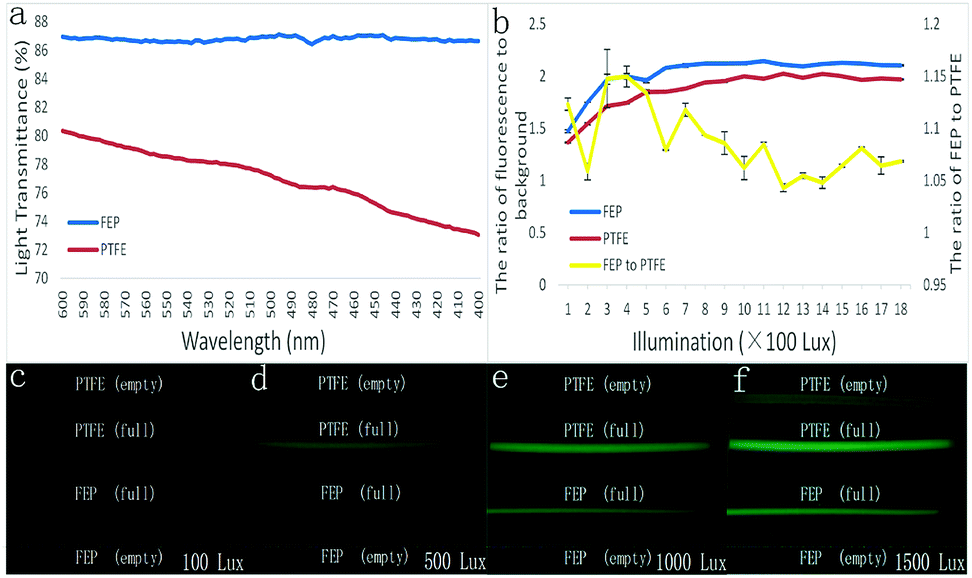 | ||
| Fig. 3 (a) The spectrophotometer measurement of the light transmittances conducted using 0.05 mm thick PTFE and FEP films. (b) The graph showing the ratio of fluorescence to background inside the PTFE and FEP tubes. (c–f) Images showing fluorescence change with different intensities of the excitation light. | ||
As shown in Fig. 3(b), regardless of the excited light intensity, the FEP tube was better than the PTFE tube in terms of the fluorescence signal ratio to the background (tubing wall) noise. The fluorescence contrast ratios of FEP were 1.47, 1.96, 2.12, and 2.12 when the illumination intensity was 100, 500, 1000, and 1500 lux, which were bigger than those of the PTFE tube, analyzed to be 1.36, 1.85, 2.00, and 2.00, respectively. Furthermore, the fluorescence contrast ratio of the FEP tube was between 1.05 and 1.15 times that of the PTFE tube when the illumination intensity was between 100 and 1800 lux.
In addition, a series of tubing images were obtained with excited light under the illumination intensity of 100, 500, 1000, and 1500 lux. It was found that the empty FEP tubes didn't interact with the excitation light at all; thus, the FEP tube displayed total darkness even under a strong light intensity as high as 1500 lux, as shown in Fig. 3(c–f). In contrast, a gradually increased fluorescence emission was found from the PTFE tube when the excitation light was increased. Moreover, the wall of the PTFE tube dramatically interacted with the fluorescent reagent inside the tube; thus, a much stronger emission light from the tubing wall was detected than that from the tube containing no reagent. In addition, because of this, the fluorescent reagent inside the FETP tube displayed a pseudomorphic diameter of 0.6 mm, much bigger than that of the FEP tube, which displayed a real diameter of 0.3 mm.
Based on the abovementioned discussions, the FEP tube may be more conducive than the PTFE tube in analyzing the fluorescence signal of the biochemical reactions inside. To prove this, the FEP tube and PTFE were further applied to two types of fluorescence-based quantitative PCRs: the continuous flow on-chip PCRs and the TEC-modulated on-chip PCRs.
3.3 The continuous flow on-chip PCRs
Both the prolonged FEP tube and the Teflon tube with the same ID of 0.3 mm were applied for sensitivity analyses of the fluorescence signal during the continues-flow PCRs. A same ID between two tubes can ensure inner fluorescence signals of the same level; however, herein, we have intentionally increased the wall thickness of the FEP tube to cause a bigger fluorescence loss when the light is passed through the FEP wall. As a result, the OD of the FEP tube herein was 1 mm, which was bigger than that of the PTFE tube (OD = 0.6 mm).Then, 3 m long FEP and PTFE tubes were both rotated around the PDMS mold, wherein the width and height of the mold were set to be 21 mm and 13.5 mm, respectively. To obtain appropriate denaturation, annealing and extension temperatures, the microdevice was put on a single heater. The annealing/extension temperature (top surface) was adjusted to approximately 62 °C, and the denaturation temperature (bottom surface) was adjusted to approximately 96 °C.
The fluorescence of the PCR reagents was excited by a 470 nm wavelength LED array. Using a digital camera, the fluorescence signals of the PCR reagents inside the Teflon tubes were detected. The syringe pump was first applied for sample flow inside both microdevices. As shown in Fig. 4(a), after the RCR reagents flowed for over 20 cycles, the fluorescence signal to background noise of the FTEP tube was much lower than that of the FEP tube considering the difference in the fluorescence transmittance.
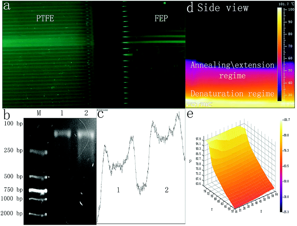 | ||
| Fig. 4 (a) Images showing the real-time fluorescence signal inside the PTFE and FEP tubes during the on-chip qPCRs. (b) Lane M shows a DL2000 marker. Lane 1 showed the target amplicon obtained using a spiral FEP microchannel. Lane 2 shows the result obtained using the commercial PCR amplification system. (c) The relative intensity scales of the target amplicons, lane 1 shows the result obtained using a spiral FEP microchannel, lane 2 shows the result obtained using the commercial PCR amplification system. (d) The side-viewed IR image of the spiral microdevice. (e) The 3D temperature distribution image across the side of the microdevice. | ||
Since it is the first time that FEP with so small ID of 0.3 mm has been applied for continuous flow on-chip PCR, we have further checked the possibility to apply a self-activated micropump to replace the externally powered syringe micropump for PCR sample transport, which is significant for device-miniaturization in the future. To maintain a self-activated sample flow, 60 μL PCR reagents were added to a syringe with the piston pushed from initial scale of 20 mL to 10 mL, with the outlet of the microdevice gently modified by connecting a 10 cm long blunt-ended silicone tube (ID 1 mm, OD 2 mm). As shown in Fig. 4(b), the agarose gel electrophoresis image showed that the DNA amplification results obtained using the microdevice or commercial qPCR cycler (Bio Rad) were similar. Through the analyses of the intensity of lanes 1 and 2, as shown in Fig. 4(c), based on the calculation conducted using the ImageJ software, the target amplicon obtained using the abovementioned microdevice was approximately 86.33% of that obtained using the thermal cycler.
3.4 The TEC-modulated on-chip PCRs
The TEC-modulated on-chip PCRs were further applied to compare the intensity difference of the fluorescence signal during the qPCRs. The same volume of the fluorescent PCR reagents was added to the 50 mm long PTFE and FEP tubes with the same ID of 0.3 mm. Then, both tubes were fixed on the surface of the silicon plate, which was located on top of the thermal cycler for temperature control. The thermal cycler program was set to contain 40 cycles (94 °C, 10 s, 60 °C, 40 s). As shown in Fig. 5(a), the thermal cycles were confirmed using the analyzIR software. A 470 nm wavelength LED array filtered with a narrow band-pass filter (470 nm) was used as the excitation light source, and the light source was turned on for 5 seconds for each cycle during the annealing temperature. The fluorescence images were obtained by a digital camera with its lens covered by an emission filter (520 nm). Fig. 5(d)–(e) show the front and side views of the overall experimental device when the DNA targets are amplified inside the Teflon tubes. As shown in Fig. 5(b)–(c), the surface temperature of the silicon plate was measured using an infrared camera, and the IR images showed that the average annealing/extension was performed at 58–62 °C, whereas denaturation was performed at 94 °C.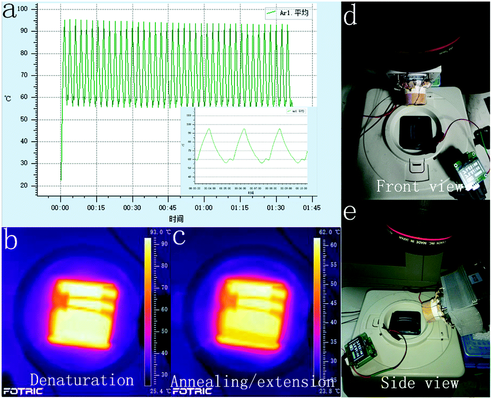 | ||
| Fig. 5 (a) The surface temperature controlled by the TEC-modulated device, and the IR camera images showing temperature distribution at (b) denaturation and (c) annealing/extension steps. (d) Front view, and (e) side view of the PCR amplification device. | ||
The fluorescence contrast of the FEP tubes and the PTFE tubes is demonstrated in Fig. 6. During the real-time PCR process, the fluorescence signal of the DNA reagents inside both the PTFE tubes and FEP tubes became brighter and brighter as the thermal cycles proceeded. In the initial cycle, it was difficult to distinguish the FEP tubes from the background; however, the PTFE tubes displayed much stronger fluorescence than the FEP tubes even without DNA amplification, in accordance with previous results. The fluorescence images of each cycle were then analyzed by the ImageJ software. The fluorescence curve in Fig. 6(a) shows that the initial fluorescence intensity of PTFE tubes is obviously higher than that of the FEP tubes. However, the FEP tubes had a much higher signal increase than the PTFE tube; thus, the amplification curve plotted against the FEP tube was closer to that of the real-time qPCR cycler than the case for the PTFE tube. Although the fluorescence curve (Fig. 6(a)) was not as smooth as that of the commercial real-time fluorescence cycler (Fig. 5(b)), similar amplification trend could be found for both cases. The average Ct value of the two FEP tubes was 19.6, and the Ct value for the commercial real-time fluorescence cycler was 16.10. In contrast, it is difficult to calculate the Ct values for the two PTFE tubes because for the PTFE tubes, the fluorescence intensity dissimilarity is small considering the overall process.
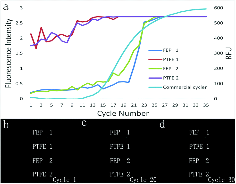 | ||
| Fig. 6 (a) PCR amplification curves obtained from the fluorescence images of the Teflon tubes and the amplification curve obtained from the commercial real-time PCR amplification system. (b–d) Series of images demonstrating the changes in the fluorescence intensity inside the PTFE and FEP tubes at 1st, 20th and 30th cycle. | ||
4 Conclusion
Through the novel tubing-modification method as characterized herein, various types of commercially available Teflon tubes with different inner and outer diameters (from 0.3 mm to 1.6 mm) can be manually adjusted. To affirm the significance of this method, the inner diameter (ID) of the FEP tube is decreased from 0.5 mm to 0.3 mm, whereas its outer diameter (OD) is decreased from 0.9 mm to 0.6 mm or 1.6 mm to 1 mm, with the tensile force accurately measured. The performance of the modified Teflon tubes was systemically studied considering the fluorescence sensitivity and spectrophotometric results.The modified FEP tube and the PTFE tube with the same diameter have been analyzed for both the TEC-modulated on-chip PCRs and the continuous flow on-chip PCRs. Herein, it was found that the ratio of the fluorescence signal to background noise of the FEP tube was much higher than that of the PTFE tube during gene amplification although the same Teflon tube (ID = 0.3 mm, OD = 0.6 mm) was successfully applied for on-chip PCRs in previous reports. When the self-activated micropump is applied for sample transport inside the FEP tube with a single thermostatic heater for thermal cycling, the amplification efficiency of the tubing device reaches 86.33% that of the commercial PCR cycler. When the Teflon tubes are applied for real-time on-chip qPCRs with a circulating temperature control unit, the amplification curve obtained from the FEP tube is also much better than that for the PTFE tube under the same cycling conditions.
Conflicts of interest
There are no conflicts to declare.Acknowledgements
This project was supported by the CAS Pioneer Hundred Talents Program, the National Natural Science Foundation of China (No. 61704169), the Natural Science Foundation of Jilin Province (20180520112JH), and the talent project of Jilin Province.References
- C. J. Easley, J. M. Karlinsey, J. M. Bienvenue, L. A. Legendre, M. G. Roper, S. H. Feldman, M. A. Hughes, E. L. Hewlett, T. J. Merkel and J. P. Ferrance, Proc. Natl. Acad. Sci. U. S. A., 2006, 103, 19272–19277 CrossRef CAS.
- Y. Yu, B. Li, C. A. Baker, X. Zhang and M. G. Roper, Anal. Chem., 2012, 84, 2825 CrossRef CAS PubMed.
- D. J. Eastburn, S. Adam and A. R. Abate, Anal. Chem., 2013, 85, 8016–8021 CrossRef CAS PubMed.
- H. Sun, Anal. Biochem., 2016, 508, 1–8 CrossRef CAS.
- M. H. Horrocks, L. Tosatto, A. J. Dear, G. A. Garcia, M. Iljina, N. Cremades, S. M. Dalla, T. P. Knowles, C. M. Dobson and D. Klenerman, Anal. Chem., 2015, 87, 8818–8826 CrossRef CAS.
- S. Santiago-Felipe, L. A. Tortajada-Genaro, R. Puchades and Á. Maquieira, Microchim. Acta, 2016, 183, 1195–1202 CrossRef CAS.
- W. Wu and A. Manz, RSC Adv., 2017, 7, 32710–32720 RSC.
- H. Liu, J. Feng, J. Zhang, P. W. Miller, L. Chen and C. Su, Chem. Sci., 2015, 6, 2292–2296 RSC.
- B. Harink, S. Le Gac, D. Barata, C. van Blitterswijk and P. Habibovic, Electrophoresis, 2015, 36, 475–484 CrossRef CAS PubMed.
- B. Shu, C. Zhang and D. Xing, Biosens. Bioelectron., 2017, 97, 360–368 CrossRef CAS PubMed.
- K. Y. Fong, M. Poot and H. X. Tang, Nano Lett., 2015, 15, 6116–6120 CrossRef CAS PubMed.
- A. Pourmand, S. A. M. Shaegh, H. B. Ghavifekr, E. Najafi Aghdam, M. R. Dokmeci, A. Khademhosseini and Y. S. Zhang, Sens. Actuators, B, 2018, 262, 625–636 CrossRef CAS.
- W. Wu, K. Kang and N. Y. Lee, Analyst, 2011, 136, 2287 RSC.
- M. U. Kopp, A. J. de Mello and A. Manz, Science, 1998, 280, 1046–1048 CrossRef CAS PubMed.
- W. Wu and N. Y. Lee, Anal. Bioanal. Chem., 2011, 400, 2053–2060 CrossRef CAS PubMed.
- W. Wu, T. L. T. Kieu and N. Y. Lee, Analyst, 2012, 137, 2069–2076 RSC.
- W. Wu, J. Wu, J. Kim and N. Y. Lee, Lab Chip, 2015, 15, 2819–2825 RSC.
- W. Wu and A. Manz, RSC Adv., 2015, 5, 70737–70742 RSC.
- W. Wu, R. M. Guijt, Y. E. Silina, M. Koch and A. Manz, RSC Adv., 2016, 6, 22469–22475 RSC.
- W. Wu and N. Y. Lee, Sens. Actuators, B, 2013, 181, 756–765 CrossRef CAS.
- W. Wu, K. T. L. Trinh and N. Y. Lee, Analyst, 2012, 137, 983–990 RSC.
- W. Wu, K. T. L. Trinh, Y. Zhanga and N. Y. Lee, RSC Adv., 2015, 5, 12071–12077 RSC.
- D. Wu, J. Xu, L. Niu, S. Wu, K. Midorikawa and K. Sugioka, Light: Sci. Appl., 2015, 4, e228 CrossRef CAS.
- W. Wu, K. T. L. Trinha and N. Y. Lee, Analyst, 2015, 140, 1416–1420 RSC.
- W. Zhang, N. Li, D. Koga, Y. Zhang, H. Zeng, H. Nakajima, J. Lin and K. Uchiyama, Anal. Chem., 2018, 90, 5329–5334 CrossRef CAS PubMed.
- A. C. Hatch, T. Ray, K. Lintecum and C. Youngbull, Lab Chip, 2014, 14, 562–568 RSC.
- A. L. Markey, S. Mohr and P. J. R. Day, Methods, 2010, 50, 277–281 CrossRef CAS PubMed.
- B. Shu, C. Zhang and D. Xing, Lab Chip, 2015, 15, 2597–2605 RSC.
- K. T. L. Trinh and N. Y. Lee, Talanta, 2018, 176, 544–550 CrossRef CAS PubMed.
- J. Chen, Z. Luo, L. Li, J. He, L. Li, J. Zhu, P. Wu and L. He, Lab Chip, 2018, 18, 412–421 RSC.
- T. L. T. Kieu, W. Wu and N. Y. Lee, RSC Adv., 2017, 7, 10624–10630 RSC.
- B. Shu, C. Zhang and D. Xing, Biosens. Bioelectron., 2017, 97, 360–368 CrossRef CAS PubMed.
- B. Shu, C. Zhang and D. Xing, Anal. Chim. Acta, 2014, 826, 51–60 CrossRef CAS PubMed.
Footnote |
| † These authors contributed equally to this work. |
| This journal is © The Royal Society of Chemistry 2019 |