
 Open Access Article
 This Open Access Article is licensed under a Creative Commons Attribution-Non Commercial 3.0 Unported Licence
Specific capture of glycosylated graphene oxide by an asialoglycoprotein receptor: a strategic approach for liver-targeting
Kevin R. Diaz-Galvez a,
Nayelli G. Teran-Saavedraa,
Alexel J. Burgara-Estrellab,
Daniel Fernandez-Quirozb,
Erika Silva-Campab,
Monica Acosta-Eliasb,
Hector M. Sarabia-Sainzc,
Martín R. Pedroza-Monterob and
Jose A. Sarabia-Sainz*b
a,
Nayelli G. Teran-Saavedraa,
Alexel J. Burgara-Estrellab,
Daniel Fernandez-Quirozb,
Erika Silva-Campab,
Monica Acosta-Eliasb,
Hector M. Sarabia-Sainzc,
Martín R. Pedroza-Monterob and
Jose A. Sarabia-Sainz*b
aDepartamento de Investigación en Polímeros y Materiales, Universidad de Sonora, Hermosillo, Mexico
bDepartamento de Investigación en Física, Universidad de Sonora, Hermosillo, Mexico. E-mail: jose.sarabia@unison.mx
cDepartamento de Ciencias del Deporte y de la Actividad Física, Universidad de Sonora, Hermosillo, Mexico
First published on 29th March 2019
Abstract
In this work, we report the evaluation of lactosylated graphene oxide (GO-AL) as a potential drug carrier targeted at an asialoglycoprotein receptor (ASGPR) from hepatic cancer cells. Structural-modification, safety evaluation, and functional analysis of GO-AL were performed. The structure and morphology of the composite were analyzed by scanning electron microscopy (SEM) and atomic force microscopy (AFM), while Raman and FTIR spectroscopy were used to track the chemical modification. For the safe application of GO-AL, an evaluation of the cytotoxic effect, hemolytic properties, and specific interactions of the glycoconjugate were also studied. SEM and AFM analysis of the GO showed graphene sheets with a layer size of 2–3 nm, though a few of them reached 4 nm. The Raman spectra presented characteristic peaks of graphene oxide at 1608 cm−1 and 1350 cm−1, corresponding to G and D bands, respectively. Besides, Si–O peaks for the APTES conjugates of GO were identified by FTIR spectroscopy. No cytotoxic or hemolytic effects were observed for GO samples, thus proving their biocompatibility. The interaction of Ricinus communis lectin confirmed that GO-AL has a biorecognition capability and an exposed galactose structure. This biorecognition capability was accompanied by the determination of the specific absorption of lactosylated GO by HepG2 cells mediated through the asialoglycoprotein receptor. The successful conjugation, hemolytic safety, and specific recognition described here for lactosylated GO indicate its promise as an efficient drug-delivery vehicle to hepatic tissue.
1. Introduction
Graphene oxide (GO) possesses a unique combination of physical and chemical properties with potential applications in nanoelectronics, nanosensor production, and the synthesis of bio-composites.1 These carbon-based nanomaterials are highly dispersible in water and have hydrophilic functional groups that enable chemical functionalization and a high surface area for the immobilization of molecules.2 These properties can be applied in biomedicine and clinical settings. Recently, GO obtained by the oxidation of graphite under acidic conditions, as first described by Hummers and Offeman,3 has been studied for in vitro drug deliveries and cellular imaging.4 GO has also been employed as a carrier for the controlled release of antitumor agents.5GO nanomaterials can be engineered for target-drug delivery through their surface functionalization with different biomolecules. Conjugating GO with tumor-selective molecules such as peptides, ligands, and antibodies could potentially improve the in vivo targeting of anti-cancer drugs. In this sense, the high specificity of the asialoglycoprotein receptor (ASGPR) towards some carbohydrates can be explored.6 ASGPRs are lectin receptors located on the sinusoidal membrane of hepatocytes. They bind and remove asialoglycoproteins, like “old immunoglobulins”, from circulation. ASGPR is the most common target site of the liver because of the high expression of hepatocytes and hepatoma cells.6 Other benefits include ease of access from the vascular compartment and the ability to internalize large molecules through clathrin-mediated endocytosis.7,8
Various groups have reported hepatocyte-specific targeted delivery via ASGPR using simple or complex sugars as a ligand coupled with the carriers.9 Roggenbuck, Mytilinaiou et al.10 reported that saccharides containing D-galactose, N-acetylgalactosamine or D-glucose residues are potential ligands for the targeting of liver cells mediated by ASGPR recognition. Arabinogalactan, a polymer based on galactose, and pullulan, a polymer based on glucose, are among the carbohydrate ligands most widely studied for liver targeting.11,12 However, lactose has shown greater affinity and specificity towards ASGPR than other ligands13 due to the lactose structure being composed of galactose and glucose (β-D-galactopyranosyl-(1-4)-D-glucose), forming a disaccharide that complies with the key factors for the interaction with ASGPR.
This work aimed to synthesize lactose-modified graphene oxide (GO-AL) to promote a specific interaction with hepatic receptors. The nanomaterials were obtained by the oxidation of graphite, and then lactosylation was performed by thermal glycation. The obtained nanocomposite was characterized physicochemically, and its biocompatibility properties were also evaluated. The exposure of galactose for specific recognition was studied using carbohydrate-specific lectins as well as the selective HepG2 cell uptake.
2. Experimental
2.1. Materials
Graphite flakes, fluorescein-NHS, Dulbecco's modified Eagle's medium (DMEM), and fetal bovine serum (FBS) were purchased from Sigma-Aldrich (St. Louis, MO, USA). HepG2 (human liver cancer) and HeLa (human cervical carcinoma) cells were obtained from ATCC (Manassas, VA, USA). Unless specified, all other reagents and chemicals were purchased from Sigma-Aldrich. All the experiments were carried out using Type 2 pure water (0.18 μS cm−1).2.2. Preparation of graphene oxide
Oxidation of graphite was carried out according to the modified Hummers method.3 Briefly, graphite powder (0.25 g) was suspended in sulfuric acid (H2SO4, 15 mL) and was kept in an ice bath for 25 min with stirring. Subsequently, sodium nitrate (NaNO3, 0.25 g) was added to the suspension and the mixture was stirred for 60 min. Then, potassium permanganate (1.2 g) was slowly added, maintaining a temperature of 35 °C for 60 min. Later, 50 mL of water was added, and then hydrogen peroxide (5 mL, 30 vol%) was slowly added to the reaction mixture with stirring for 30 min. In this step, an exothermic effect was produced with the mixture reaching a temperature ∼73 °C, which was then cooled in an ice bath. Finally, the samples were washed using water and several centrifugation cycles were applied (2422 × g, 10 min at 25 °C).For the complete exfoliation of GO, the resultant suspension (20 mL) was sonicated in an ice bath (Q500 ultrasonic processor, 500 watts, QSONICA, 30 pulses, 35% amplitude dial setting) for 15 min. Then, the suspension was centrifuged (2422 × g, 10 min at 25 °C), and the precipitate was dehydrated at 60 °C for 7 days.
2.3. Graphene oxide lactosylation
Functionalization of the GO with lactose was performed as follows: first, 50 mg of GO was suspended in 30 mL of ethanol. Then, (3-aminopropyl)triethoxysilane (APTES, 2.4 mM) was added to the solution and stirred at 40 °C for 24 h. The resulting particles were washed two times with water (2422 × g for 10 min), then the supernatant was discarded, and the resultant pellet was resuspended in 20 mL of water. Once GO with –NH2 groups was obtained, lactose (50 mg) was added and the solution was left at 40 °C for 3 days to promote the glycation reaction. After incubation, the suspension was washed with water and centrifuged (2422 × g for 10 min). Next, the lactosylated GO (GO-AL) was precipitated by centrifugation and dried at 60 °C for 7 days. As a control, GO without modification and GO modified with APTES (GO-A) samples were prepared.2.4. Characterization of the lactosylated graphene oxide
Raman spectra of GO, GO-A, and GO-AL samples were acquired with a Raman micro-spectrometer (Alpha300RA, WiTec, Ulm, Germany) using a frequency doubled Nd:YAG laser excitation of 532 nm (CW – continuous wave). The samples were prepared as follows: 10 mg of the resultant powder was suspended in 500 μL of water, and then 10 μL of the suspension was placed on a silicon substrate, allowed to dry, and subsequently the Raman spectrum was obtained. The Raman measurements were carried out with 10 s accumulation time, 10 mW laser power, and a 0.68 μm spot size. FTIR spectra were obtained using a FTIR Perkin-Elmer Frontier spectrometer. Approximately 5 mg portions of the dry samples were directly dispersed into a KBr pellet for the FTIR measurements. Background spectra were collected using pure KBr pellets. The spectra were recorded at room temperature over 16 scans, using a resolution of 4 cm−1.2.5. Morphological characterization
The morphology of GO and functionalized GO were characterized by scanning electron microscopy (SEM; JEOL, JSM-7800F, Akishima, Tokyo, Japan) and atomic force microscopy (Alpha300RA, WiTec, Ulm, Germany). SEM images were obtained with a magnification of ×10![[thin space (1/6-em)]](https://www.rsc.org/images/entities/char_2009.gif) 000 using an acceleration voltage of 5.0 kV. Atomic force microscopy (AFM) images were reconstructed in the non-contact mode using a probe with a spring constant of 42 N m−1 and a resonant frequency of 285 kHz. An optical microscope was used to focus the sample on the slice, and then the area of analysis of the GO sheets was randomly selected and scanned. The shape analysis was performed from 5 × 5 μm scans for each specimen. The morphology and height profile of the GO and functionalized GO were analyzed with the software program WiTec project FOUR v4.1.
000 using an acceleration voltage of 5.0 kV. Atomic force microscopy (AFM) images were reconstructed in the non-contact mode using a probe with a spring constant of 42 N m−1 and a resonant frequency of 285 kHz. An optical microscope was used to focus the sample on the slice, and then the area of analysis of the GO sheets was randomly selected and scanned. The shape analysis was performed from 5 × 5 μm scans for each specimen. The morphology and height profile of the GO and functionalized GO were analyzed with the software program WiTec project FOUR v4.1.
2.6. Zeta potential
The zeta potential of GO samples was determined by laser Doppler anemometry using a Zetasizer Nano ZS 90 instrument (Malvern Instruments Ltd., Malvern, UK). The measurements were performed at 25 °C. The GO samples (1 mg mL−1) were dispersed in 10 mM phosphate buffer saline (PBS) at pH 7.2, saline solution, DMEM (Dulbecco modified eagles medium), or water. All the measurements were done in triplicate.2.7. Enzyme-linked lectin assay (ELLA): GO-lactose confirmation
The interaction of Ricinus communis agglutinin I (RCA) with lactosylated GO was analyzed by ELLA. Briefly, samples were adsorbed on an ELISA plate, with 50 mg 100 μL−1 (PBS with 1 vol% of glutaraldehyde, pH 7.2) placed in wells and incubated for 2 h. After extensive washes with PBS, the wells were blocked for 3 h with 1.5% BSA in PBS. Then, 100 μL of biotin-labeled RCA (1 mg mL−1) was added and incubated for 2 h. After four washes with PBS, the plates were treated with avidin–peroxidase (1/1000 v/v in PBS, pH 7.5) for 1 h and the interaction was revealed using O-phenylenediamine. GO and GO modified only with APTES were used as the negative controls.2.8. In vitro biocompatibility of GO studies
:1000 μL). RBC dilution (1 mL) was mixed with 0–100 μg mL−1 of GO samples. After 3 h of incubation at room temperature, RBCs were centrifuged (2000 × g for 10 min) and hemolysis was analyzed by absorbance at 540 nm using a spectrophotometer (Thermo Scientific Multiskan GO spectrophotometer). RBCs diluted in water were used as the positive control.2.9. Cellular uptake evaluation and specificity of recognition
To evaluate the cellular uptake, GO-A and GO-AL were labeled with fluorescein and studied on ASGPR-positive hepatoma cells HepG2 as well as ASGPR-negative HeLa cells. Cells were seeded in 48-well plates at a density of 10000 cells/200 μL per well using DMEM containing 10% FBS. After incubation (5% CO2 at 37 °C for 24 h), the cells were washed against sterile saline solution (SSS) three times, and subsequently were incubated with PBS, GO-A, or GO-AL at 10 μg mL−1 at 37 °C for 30 min. The cells were rinsed two times with SSS (200 μL per well). Finally, the cells were observed by confocal microscopy (Nikon Ti Eclipse C2+) with 488 nm lasers at ×20 magnification. At the same time, as a competitive assay, the cells were simultaneously incubated with GO samples and free lactose, while for the biorecognition inhibition assay, the cells were previously incubated with lactose (10 μg/100 mL of DMEM) and the GO samples (10 μg mL−1) were added 30 min later.
2.10. Statistical analysis
The experiments were performed in triplicate and evaluated by analysis of variance (ANOVA). Also, the data results from the ELLA were analyzed by the application of the Tukey–Kramer test with p ≤ 0.05 using NCSS 2007 (Statistical Analysis and Graphics, Kaysville, UT, USA).3. Results and discussion
3.1. Functionalization of GO with lactose
The successful synthesis of GO sheets, APTES coating, and subsequent glycation with lactose were analyzed by Raman spectroscopy (Fig. 1). Characteristic Raman absorption bands for carbon sp2 forms (C–C bond stretch) were observed at 1608 cm−1 for GO and at 1590 cm−1 for GO-A and GO-AL, respectively. These Raman shifts are known as the G band.15 The band associated with sp3 forms is the D band, and in GO this is attributed to the reduction in the size of the sp2 domains by the creation of defects, vacancies, and distortions during the oxidation of graphite.15,16 All the GO sample spectra showed the D band at 1350 cm−1. The intensity of this band is indicative of the presence of an sp3 form, which confirmed the grafting of oxygen-containing functional groups to the graphitic plans.16 The ratio D/G (ID/G) showed a dependent increase with the degree of modification of GO. Fig. 1 illustrates the ID/G for GO-AL, GO-A, and GO (0.99, 0.96, and 0.91, respectively). This behavior has been reported and reveals an increase in the amount of sp3 hybridized carbon atoms due to disordered domains and defect structures of graphene induced by the covalent bonding with APTES.17 The GO-AL Raman spectra exhibited bands that also could be observed in the APTES spectrum and lactose spectrum at 1028 cm−1 (Si–OH stretching vibration) and 1118 cm−1, respectively. The above results suggest the successful lactosylation of GO.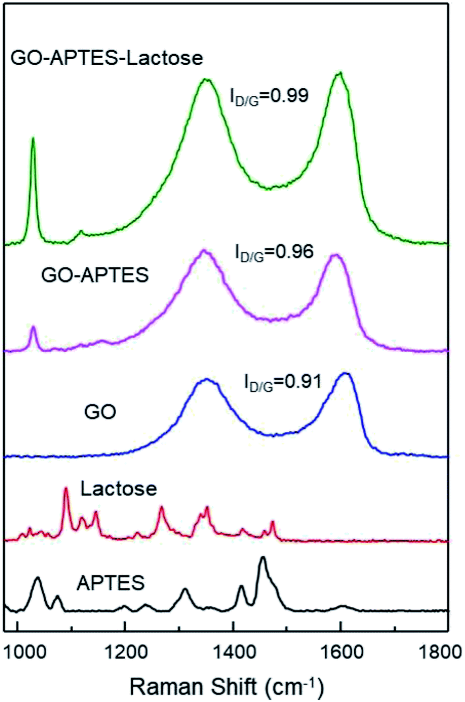 | ||
| Fig. 1 Raman spectra of APTES, lactose, GO, GO-APTES, and GO-APTES-lactose. | ||
Additionally, chemical modifications of GO were analyzed by FTIR spectroscopy. The FTIR spectra of the GO, GO-A, and GO-AL are shown in Fig. 2. The presence of a new band was observed as a significant change in the spectrum of the modified GO (GO-A and GO-AL) at 901 cm−1, corresponding to Si–O and amino groups, attributed to the APTES conjugation.18 The characteristic infrared bands of carbohydrates are localized between 900 and 1199 cm−1;19 nevertheless, these were shifted and referred to the SiO-X region.18 We observed slight differences in this region for both GO-A and GO-AL, which made it difficult to identify the lactose groups. However, due to the conjugation of GO, the band observed at 1730 cm−1 (C–O stretching peak for carboxylic acid) vanished, but it was also evident that there was an intensification of the band at about 1600 cm−1.
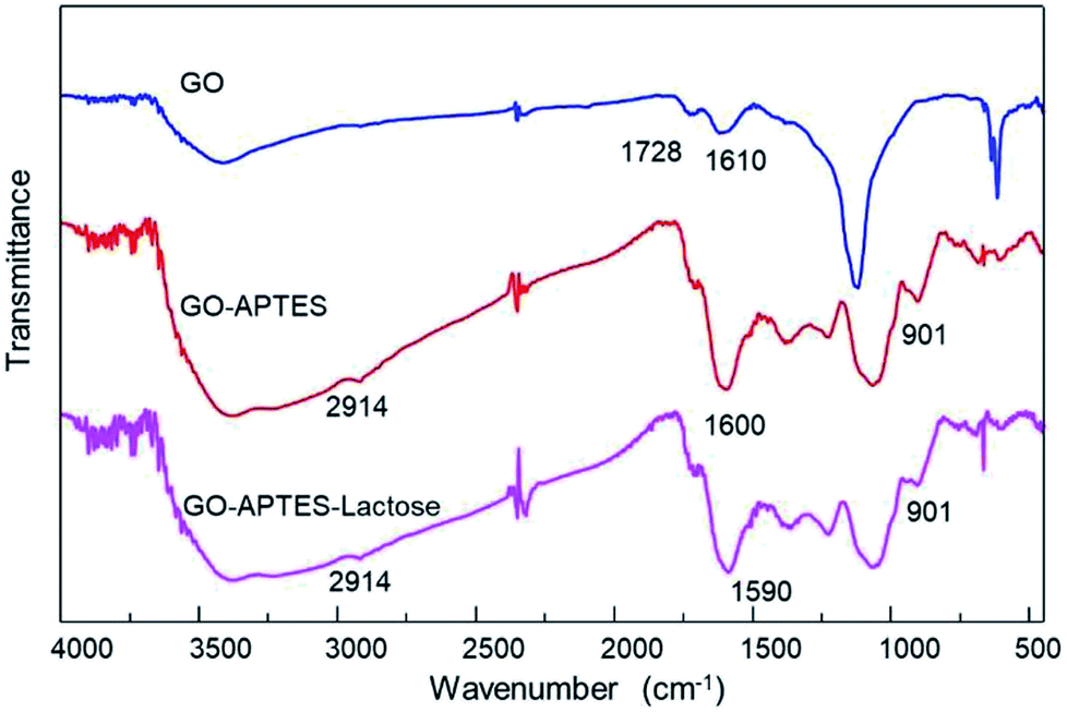 | ||
| Fig. 2 ATR-FTIR spectra of GO, GO-APTES (GO-A), and GO-APTES-lactose (GO-AL). | ||
Similar behavior was described by Cao et al.,20 who previously described the presence of a new prominent band at 1639 cm−1 corresponding to the stretching mode of amide groups by the conjugation of GO with lactosylated chitosan. Also, Sarkar et al.21 reported the occurrence of a new absorption band at 1630 cm−1 due to the modification of GO with aminated molecules. Finally, the GO-A and GO-AL spectra showed a shift at 2092 cm−1 corresponding to the primary amine group. The above results confirm the modification with APTES and suggests the presence of lactose in GO-AL.
3.2. Ricinus communis-lactose recognition
Due to the ability of lectins to bind or specifically recognize carbohydrate residues, these plant proteins are considered as an excellent tool to characterize simple or complex carbohydrates present in different kinds of glycoconjugates. The lactosylation of GO was carried out first by the reaction with an aminated compound (APTES), which aided the reaction as a bridge for the subsequent glycation with lactose. The glycation reaction occurred by the formation of a Schiff base between the aldehyde group of the reducing sugar (such as glucose) and the primary amino group of a macromolecule. We modified GO with APTES and then exposed it to lactose to obtain GO-APTES-lactose (GO-AL). The reaction was verified using RCA lectin, which recognizes galactoses. GO-AL samples were consistently recognized by RCA (Fig. 3), which indicated the presence of lactose in the GO sheets subjected to glycation. It also confirmed the correct closed ring structure of galactose, which is a requirement for the interaction with carbohydrate receptors.22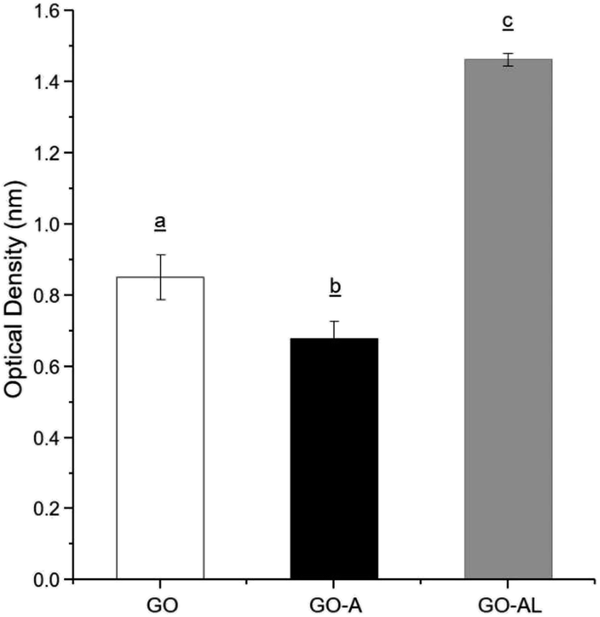 | ||
| Fig. 3 ELLA for the recognition of GO, GO-A, and GO-AL by Ricinus communis lectin. Experiments were performed in triplicate and analysis was by ANOVA followed by Tukey's test; p ≤ 0.05. Different letter (a, b, and c) shows statistical significance. | ||
3.3. Zeta potential
The colloidal stabilities of the GO, GO-A, and GO-AL were determined by measuring the zeta potential. The colloidal dispersion is stable when a force causes the mutual repulsion of the particles.23 In general, a particle suspension with a zeta potential of around −30 mV is considered as a stable dispersion.24 Table 1 shows the zeta potential values of the GO samples. The zeta potential values for all the GO samples were above −40 mV when dispersed in water. The zeta potential values decreased to around −20 mV when the GO samples were dispersed in physiological saline solution or PBS. Furthermore, a minor negative charge of around −15 mV was observed in the culture medium (DMEM). The moderate zeta potential (−20 mV) of the GO samples in an electrolytic solution (saline solution or PBS) can be explained by the characteristic screening effect. The low zeta potential in DMEM can be attributed to the complex content of the molecules of this culture medium (aminoacids, vitamins, glucose, and salts) that can interact with the surface of the GO sheets, decreasing its superficial charge.| GO | GO-A | GO-AL | |
|---|---|---|---|
| a Zeta potential values are shown as the mean ± standard deviation. Abbreviations: GO, graphene oxide; GO-A, graphene oxide-APTES; GO-AL, lactosylated graphene oxide; SS, saline solution; PBS, phosphate buffer saline; RPMI, Roswell Park Memorial Institute medium. | |||
| Water | −42.6 ± 3.06 | −45.3 ± 6.86 | −43.3 ± 5.33 |
| SS | −16.2 ± 9.54 | −25.8 ± 11.60 | −20.5 ± 3.46 |
| PBS | −22.2 ± 9.27 | −19.9 ± 8.38 | −19.6 ± 11.10 |
| DMEM | −16.9 ± 2.93 | −14.9 ± 1.27 | −14.7 ± 1.53 |
3.4. Morphological characterization of GO and lactosylated GO
The GO and lactosylated GO samples were observed by SEM and AFM (Fig. 4). SEM images (Fig. 4A and B) show a sheet structure of graphite as a single or stack of several layers with a variety of sizes. Also, it is possible to observe a laminar appearance for the GO-AL, while the GO is shown as corrugated sheet structures. The AFM images show the morphology and the height profiles of GO and the functionalized GO. Dispersed structures with some aggregation can be observed for both GO and functionalized GO (Fig. 4C and D). Analysis of the height profiles from the dispersed GO structures revealed a thickness of 2.396 ± 1.29 nm for GO and 2.72 ± 2.51 nm for GOL (Fig. 4E and F), which is consistent with previous reports for GO composites.16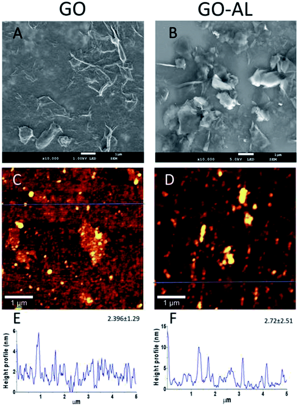 | ||
| Fig. 4 Morphology and profile height of GO and the functionalized GO. (A and B) SEM image; (C and D) representative AFM image of GO morphology; (E and F) representative height profile from dispersed structures of GO, extracted from the blue line. The mean of the height and the standard deviation is also presented (N = 3). | ||
3.5. Hemolytic properties of GO
Red blood cells (RBCs) are the most abundant cells in blood; likewise, these cells are in continuous contact with exogenous compounds that reach the circulatory system. The application of nanoparticles as therapeutic agents should consider that these will have an interaction with components in blood, mainly the RBCs. In this context, we evaluated the hemolytic effect of GO samples. Fig. 5 shows that none of the GO samples presented any hemolytic effect, even over 100 μg mL−1. In Fig. 5A, we can see the viability graph of RBCs treated with GO, GO-A, and GO-AL. Also, the photographs of centrifuged RBCs incubated with GO samples shows the RBCs at the bottom and the supernatant without evidence of the red color representing free hemoglobin (Fig. 5B). It is important to mention that when increasing the GO concentration, the sheets tended to aggregate induced by the neutralization of charges with the ions dissolved in PBS.25 The above can lead to a false negative of the hemolytic properties; however, in our results, even at a low concentration of GO samples (0.25–50 μg mL−1), no hemolysis was observed.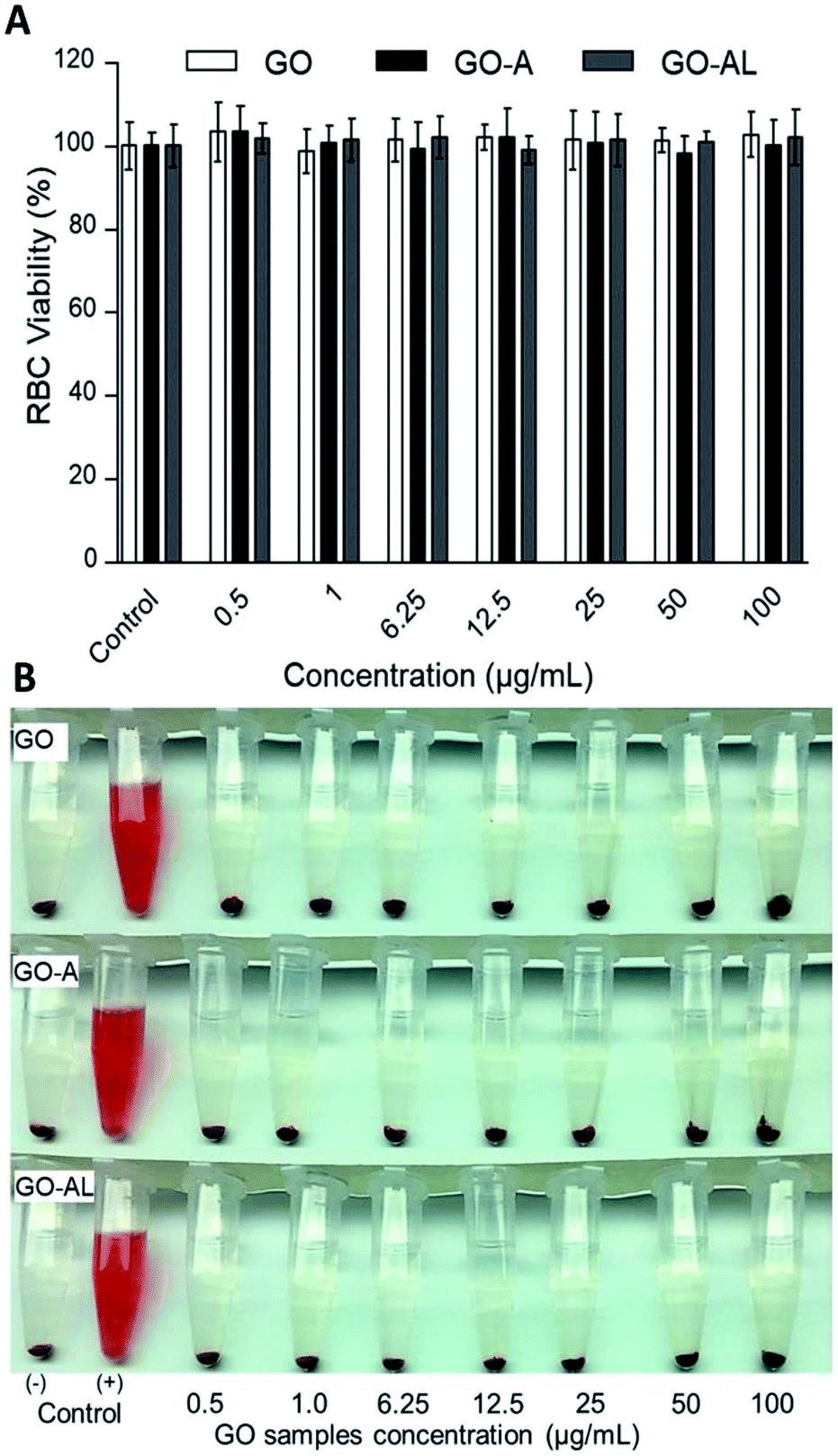 | ||
| Fig. 5 Red blood cell (RBC) viability assay. RBCs were incubated with different concentration (0.5 to 100 μg mL−1) of GO, GO-A, or GO-AL. (A) Graphic representation of RBC viability was determined based on the degree of hemolysis. Data are the mean ± standard deviation for three separate experiments. (B) Photographs of RBCs treated with GO samples. PBS and DI water served as the negative (−) and positive (+) controls, respectively. The experiments were repeated in triplicate. | ||
3.6. In vitro cytotoxicity in HepG2 cells
For a detailed evaluation of the cytotoxicity degree and the effects induced by the interaction of GO with hepatic cells, the MTT assay was performed. This test is based on measuring the cell viability, which is determined by the ability of mitochondria to reduce MTT. Here, the MTT results for GO samples showed no effects on the mitochondrial activity of HepG2 cells, indicating that the cells were unaffected by either nanomaterial at 0.25–100 μg mL−1 (Fig. 6). These results agreed with those reported by Yuan et al.,26 who reported that the GO samples do not show cellular toxicity below 100 μg mL−1. However, our cytotoxicity results contrast with the one reported by Wang et al.,27 whose results indicated that GO is cytotoxic, even at low concentrations (50–100 μg mL−1).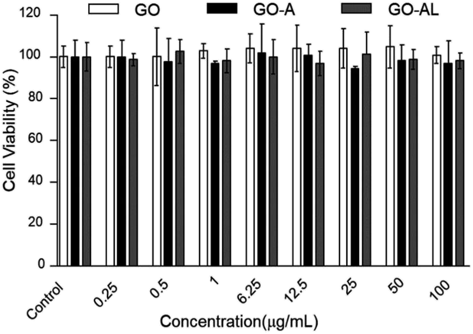 | ||
| Fig. 6 MTT cytotoxicity of GO, GO-A or GO-AL at different concentration (0.25 to 100 μg mL−1). Data are means ± standard deviation for three separate experiments. | ||
The cytotoxicity can be attributed to several factors, such as the chemical composition, size, surface, dimensional characteristics, use of reducing agents for functionalization of graphene, functional groups, charges, coatings, structural defects of graphene, and the dissolving media.28 Principally, the changes in the processes for obtaining GO can lead to a variation in the type and number of functional groups (ester, hydroxyl, and epoxide groups) and therefore, the cytotoxicity can show a discrepancy. Although none of our GO samples were cytotoxic at the concentration used (0.25–100 μg mL−1), it is relevant to indicate that the functionalization of the GO with lactose can increase its biocompatibility, as has been reported for graphene and other carbon-based materials.29
3.7. Cellular interaction evaluation and specificity of recognition
The cellular uptake interaction of FITC-labeled GO samples were studied on two different cells: ASGPR-positive cells (hepatoma cells HepG2) and ASGPR-negative cells (human cervical carcinoma cells HeLa), via confocal microscopy. Fig. 7 shows a strong green fluorescence intensity with HepG2 cells exposed to GO-AL and a null fluorescence for the HeLa cells. Likewise, it can be observed that GO-A was not visualized in HepG2 cells, indicating that the modification of GO with lactose significantly induced the cell uptake by ASGPR-positive cells. This behavior was previously reported by Lee et al.14 They suggested that the presence of lactose on the nanoparticle surface plays a crucial role in allowing internalization by hepatocytes. Bareford and Swaan30 explained that targeting the receptor–ligand pathway offers several advantages, including the ability to exploit upregulated membrane receptors in specific diseased tissues, to control the intracellular fate for localization to acidic endosomes, and to allow for the regulated release of therapeutics from the bioresponsive vehicle. Thus, it is essential to show that the internalization is specific and mediated by the receptor–ligand.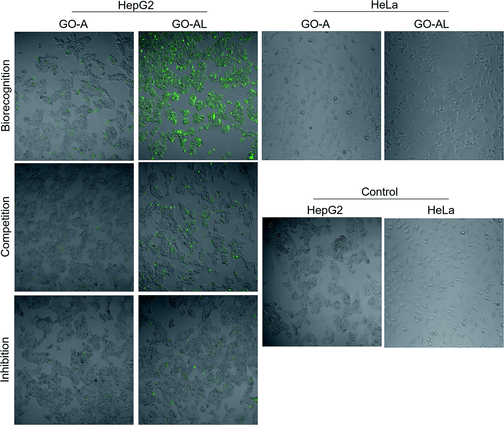 | ||
| Fig. 7 Cellular interaction evaluation and specificity of recognition. HepG2 cells were incubated with GO-A and GO-AL to evaluate the receptor–ligand interaction between ASGPRs (from HepG2 cells) and galactose (from GO-AL). HeLa cells were used as negative control. To determine specific recognition competitive and inhibition assay were performed. In competition, assay cells were simultaneously incubated with GO samples and free lactose. In inhibition, the cells were first incubated with lactose and later GO-AL was added. | ||
To determine the ability of lectins to bind specific glycoconjugates, studies of the interaction inhibition are habitually carried out using a simple, specific carbohydrate as an inhibitor.31 In this regard, we evaluate the uptake of the lactosylated GO by HepG2 cells using free lactose as the competitive or inhibitor ligand. For the competitive assay, HepG2 cells were simultaneously incubated with GO-AL and free lactose. The inhibition assay was carried out by the pre-incubation of HepG2 cells with free lactose followed by GO-AL addition. Competitive tests (Fig. 7) showed that the fluorescence intensity of HepG2 cells treated with GO-AL + free lactose was decreased significantly compared to that of HepG2-GO-AL interactions.
Furthermore, the pre-incubation of HepG2 cells with free lactose seemed to induce saturation of the ASGPRs, which were unable to interact with the galactose exposed on GO-AL (Fig. 7). These results confirmed the selectivity of the asialoglycoprotein receptor toward the structures present in the lactosylated GO. Quan et al.32 reported similar results with ASGPR positive cells and lactosylated mesoporous silica nanoparticles. They observed that the cellular internalization of lactosylated nanoparticles by HepG2 and SMMC7721 cells decreased in the presence of excess free lactose. Therefore, we demonstrated the potential use of lactosylated GO as a targeted drug delivery system.
4. Conclusions
We presented a protocol for the conjugation of GO with lactose to obtain a glycocomposite, which did not show hemolytic and cytotoxic effects. The correct functionalization of the GO was evidenced by biorecognition with the RCA lectin and also, it allowed for specific interaction with the ASGPRs from liver cells. These results represent a promising selective drug delivery vehicle to the hepatic tissue.Conflicts of interest
There are no conflicts to declare.Acknowledgements
We are grateful to the CONACYT and SEP of Mexico for financial support, under projects PDPCPN-2014-248982, and PRODEP/DSA/103.5/16/10231.Notes and references
- K.-H. Liao, Y.-S. Lin, C. W. Macosko and C. L. Haynes, ACS Appl. Mater. Interfaces, 2011, 3, 2607–2615 CrossRef CAS PubMed.
- C. Cha, S. R. Shin, N. Annabi, M. R. Dokmeci and A. Khademhosseini, ACS Nano, 2013, 7, 2891–2897 CrossRef CAS PubMed.
- W. S. Hummers Jr and R. E. Offeman, J. Am. Chem. Soc., 1958, 80, 1339 CrossRef.
- X. Sun, Z. Liu, K. Welsher, J. T. Robinson, A. Goodwin, S. Zaric and H. Dai, Nano Res., 2008, 1, 203–212 CrossRef CAS PubMed.
- T. Zhou, X. Zhou and D. Xing, Biomaterials, 2014, 35, 4185–4194 CrossRef CAS PubMed.
- Y. Li, G. Huang, J. Diakur and L. I. Wiebe, Curr. Drug Delivery, 2008, 5, 299–302 CrossRef CAS.
- D. D. Mcabee, X. Jiang and K. B. Walsh, Biochem. J., 2000, 348, 113–117 CAS.
- A. A. D'souza and P. V. Devarajan, J. Controlled Release, 2015, 203, 126–139 CrossRef PubMed.
- S. Pranatharthiharan, M. D. Patel, V. C. Malshe, V. Pujari, A. Gorakshakar, M. Madkaikar, K. Ghosh and P. V. Devarajan, Drug Delivery, 2017, 24, 20–29 CrossRef CAS PubMed.
- D. Roggenbuck, M. G. Mytilinaiou, S. V. Lapin, D. Reinhold and K. Conrad, Autoimmun. Highlights, 2012, 3, 119–125 CrossRef CAS PubMed.
- Y. Kaneo, T. Tanaka, T. Nakano and Y. Yamaguchi, J. Controlled Release, 2001, 70, 365–373 CrossRef CAS PubMed.
- T. Tanaka, S. Hamano, Y. Fujishima and Y. Kaneo, Biol. Pharm. Bull., 2005, 28, 560–562 CrossRef CAS.
- C. Managit, S. Kawakami, M. Nishikawa, F. Yamashita and M. Hashida, Int. J. Pharm., 2003, 266, 77–84 CrossRef CAS PubMed.
- C. Lee, B. Kim, S. Lee, T. H. Kim, J. O. Kim, E. S. Lee, K. T. Oh, H.-G. Choi, S. D. Yoo and Y. S. Youn, Colloids Surf., B, 2017, 152, 183–191 CrossRef PubMed.
- K. Krishnamoorthy, M. Veerapandian, R. Mohan and S.-J. Kim, Appl. Phys. A: Mater. Sci. Process., 2012, 106, 501–506 CrossRef CAS.
- S. Perumbilavil, P. Sankar, T. Priya Rose and R. Philip, Appl. Phys. Lett., 2015, 107, 051104 CrossRef.
- L. Hu, P. Jiang, P. Zhang, G. Bian, S. Sheng, M. Huang, Y. Bao and J. Xia, J. Mater. Sci., 2016, 51, 8296–8309 CrossRef CAS.
- R. M. Pasternack, S. Rivillon Amy and Y. J. Chabal, Langmuir, 2008, 24, 12963–12971 CrossRef CAS PubMed.
- A. Gallegos-Tabanico, J. A. Sarabia-Sainz, H. M. Sarabia-Sainz, R. C. Torres, A. M. Guzman-Partida, G. R.-C. Monfort, E. Silva-Campa, A. J. Burgara-Estrella, A. Angulo-Molina and M. Acosta-Elias, Acta Biochim. Pol., 2017, 64, 671–677 CrossRef CAS PubMed.
- X. Cao, S. Zheng, S. Zhang, Y. Wang, X. Yang, H. Duan, Y. Huang and Y. Chen, J. Nanosci. Nanotechnol., 2015, 15, 2052–2059 CrossRef CAS PubMed.
- K. Sarkar, G. Madras and K. Chatterjee, RSC Adv., 2015, 5, 50196–50211 RSC.
- A. I. Ledesma-Osuna, G. Ramos-Clamont and L. Vázquez-Moreno, Acta Biochim. Pol., 2008, 55, 491–497 CAS.
- S. Kashyap, S. Mishra and S. K. Behera, J. Nanopart., 2014, 2014, 1–6 CrossRef.
- F. Baskoro, C.-B. Wong, S. R. Kumar, C.-W. Chang, C.-H. Chen, D. W. Chen and S. J. Lue, J. Membr. Sci., 2018, 554, 253–263 CrossRef CAS.
- Y. Wang, B. Zhang and G. Zhai, RSC Adv., 2016, 6, 68322–68334 RSC.
- X. Yuan, Z. Liu, Z. Guo, Y. Ji, M. Jin and X. Wang, Nanoscale Res. Lett., 2014, 9, 108 CrossRef PubMed.
- A. Wang, K. Pu, B. Dong, Y. Liu, L. Zhang, Z. Zhang, W. Duan and Y. Zhu, J. Appl. Toxicol., 2013, 33, 1156–1164 CrossRef CAS PubMed.
- S. Gurunathan and J.-H. Kim, Int. J. Nanomed., 2016, 11, 1927 CrossRef CAS PubMed.
- Y. Chen, A. Star and S. Vidal, Chem. Soc. Rev., 2013, 42, 4532–4542 RSC.
- L. M. Bareford and P. W. Swaan, Adv. Drug Delivery Rev., 2007, 59, 748–758 CrossRef CAS PubMed.
- S. André, H. Kaltner, K. Kayser, P. V. Murphy and H.-J. Gabius, Histochem. Cell Biol., 2016, 145, 185–199 CrossRef PubMed.
- G. Quan, X. Pan, Z. Wang, Q. Wu, G. Li, L. Dian, B. Chen and C. Wu, J. Nanobiotechnol., 2015, 13, 7 CrossRef PubMed.
| This journal is © The Royal Society of Chemistry 2019 |