
 Open Access Article
 This Open Access Article is licensed under a Creative Commons Attribution-Non Commercial 3.0 Unported Licence
Effectively enhanced structural stability and electrochemical properties of LiNi0.5Mn1.5O4 cathode materials via poly-(3,4-ethylenedioxythiophene)-in situ coated for high voltage Li-ion batteries†
JinFeng Liu ,
YuFang Chen,
Jing Xu*,
WeiWei Sun,
ChunMan Zheng and
YuJie Li
,
YuFang Chen,
Jing Xu*,
WeiWei Sun,
ChunMan Zheng and
YuJie Li
College of Aerospace Science and Engineering, National University of Defense Technology, Chang Sha 410073, China. E-mail: xujin503@163.com; Tel: +8615607499928
First published on 22nd January 2019
Abstract
Spinel LiNi0.5Mn1.5O4 shows promise as a potential candidate for Li-ion batteries due to its high energy density and high rate performance. However, LiNi0.5Mn1.5O4 (LNMO) spinel oxides usually deliver poor cycle life because of the increasing impedance and gradually dissolving Mn resulting in the destruction of crystal structure. Here, a conductive polymer poly-(3,4-ethylenedioxythiophene) (PEDOT) surface modified strategy is introduced to settle the above challenges. The main purpose is to construct a uniform and dense shell film on the surface of LiNi0.5Mn1.5O4 (Industrial Grade), which is prepared by a simple chemical in situ oxidative polymerization method. The Mn dissolving from the lattice during the long-term cycling is well inhibited as the polymer shell protects LiNi0.5Mn1.5O4 from direct exposure to the highly active electrolyte. As expected, the 3 wt% poly-(3,4-ethylenedioxythiophene) coated sample reveals long cycle life with acceptable capacity of 114.5 mA h g−1 and high capacity retention of 91.6% after 200 cycles, compared to 70.9 mA h g−1 and 56.5%, respectively, for the bare LiNi0.5Mn1.5O4 sample. Furthermore, the coated sample demonstrates a higher capacity of 110 mA h g−1 and 63 mA h g−1 at 5C and 10C rate respectively. The improved performance is believed to be attributed to the formation of high conductivity and stable interface structure between electrolyte and LNMO, which is beneficial to suppress the destruction of crystalline structure due to the Mn dissolution and undesired side-reaction between electrolyte and LiNi0.5Mn1.5O4 in long cycle, and improve simultaneously the conductivity and interface stability of LiNi0.5Mn1.5O4 for high voltage lithium-ion batteries.
1. Introduction
The high energy and power density capability of lithium ion battery technology has been attracting widespread interest over the past few years due to potential applications in portable devices, hybrid electric vehicles (HEV) and full electric vehicles (EV).1–4 Many Li compounds, including olivine-type materials, silicates, Mn-rich and Ni-rich layered materials, were investigated to improve the energy density and power density of commercial lithium-ion secondary batteries.5–10 Spinel LiNi0.5Mn1.5O4 (LNMO) is a promising candidate to replace layered Ni or Co oxide materials as cathode for high power density lithium batteries.11–14 However, the commercial application of spinel LiNi0.5Mn1.5O4 is hindered by several drawbacks. Firstly, LNMO's major charge–discharge platform is up to 4.7 V, which exceeds the stable voltage (4.5 V) of the conventional LiPF6 electrolyte, leading to rapid electrolyte decomposition and unwanted side reactions occurring between the active electrode and the electrolyte.15–18 Furthermore, dissolution of Mn3+ in LNMO is another serious issue, which would cause destroyed material structure and reduced cycle life of LNMO.19–21 Meanwhile, decomposition of electrolyte causes an electrolyte/electrode interface (SEI) on the surface of LNMO during cycling, it would prevent the insertion/extraction of Li+ and result in poor cycle life.22–25In this regard, many strategies have been proposed to tailor the structures and morphologies of the LiNi0.5Mn1.5O4 materials through ion-doping, nanoarchitecture, or surface modification.26,27 Among the above-mentioned approaches, surface modification is researched mostly due to its efficiency in facing electrolyte eroding. Hence, many inorganic compounds, such as oxides, fluorides, and phosphates, were explored as the coating layer to stabilize the surface structure.15,28–33 However, these coatings will lead to lower conductivity, raise the interface impedance and have limited contribution to fast lithium ion transport of LiNi0.5Mn1.5O4.34 In this regard, Gao et al.35 constructed a inorganic/polymer combined core/shell structure by coating spinel materials with organic PPy, and this composite material shows better rate capability and cycle stability in the potential range of 3.5–4.9 V vs. Li/Li+ at 25, 55 °C. As the polymers surface modification can form a dense film on the surface of cathode materials, which show improved performance, it was widely used in coating electrode materials. PEDOT coating was reported to be more effective due to the high conductivity and stability at high potential. Such as Zhang et al.36 use PEDOT modified Li4TiO12 shows improved rate performance, and Kang et al.37 reported a PEDOT coated Li3V2(PO4)3 material without addition of conductive carbon black can effectively promote electrochemical performance.
In this paper, conductive polymer PEDOT film was in situ synthesized on the surface of LiNi0.5Mn1.5O4 by a simple chemical oxidative polymerization method. Compared with the bare material, PEDOT@LNMO composite shows significantly improved cycling stability and rate capability. The possible mechanism and effect of PEDOT coating layer on the electrochemical performance of LiNi0.5Mn1.5O4 cathode was explored in detail.
2. Experimental section
Synthesis of the PEDOT@LNMO composite
Fig. 1 illustrates the synthetic process we have newly designed for PEDOT@LNMO composites. The LNMO in this experiment was purchased from Sichuan Xingneng New Material Co. Ltd. (Industrial grade, SHBS-LNMO-100). The synthesis process contains following steps, Firstly, 1 g of purchased LNMO material was dispersed in 20 ml aqueous solution. Then, a certain solution contains EDOT and p-toluenesulfonic Acid (PTS) (EDOT![[thin space (1/6-em)]](https://www.rsc.org/images/entities/char_2009.gif) :PTS = 1.65:1 (mol)) after continuous stirring for 30 min was added. Followed by adding the Ammonium persulphate (APS) (EDOT:APS = 1:2.2 (mol)) solution with a continuous stirring. The reaction was carried out under a nitrogen atmosphere and in an ice bath over 24 h. During the synthesis process, the PEDOT layer was prepared through the oxidative polymerization of EDOT by using APS as the oxidant. Finally, the powder was washed several times with distilled water and ethanol, and dried at 80 °C overnight to obtain the PEDOT@LNMO composite.
:PTS = 1.65:1 (mol)) after continuous stirring for 30 min was added. Followed by adding the Ammonium persulphate (APS) (EDOT:APS = 1:2.2 (mol)) solution with a continuous stirring. The reaction was carried out under a nitrogen atmosphere and in an ice bath over 24 h. During the synthesis process, the PEDOT layer was prepared through the oxidative polymerization of EDOT by using APS as the oxidant. Finally, the powder was washed several times with distilled water and ethanol, and dried at 80 °C overnight to obtain the PEDOT@LNMO composite.
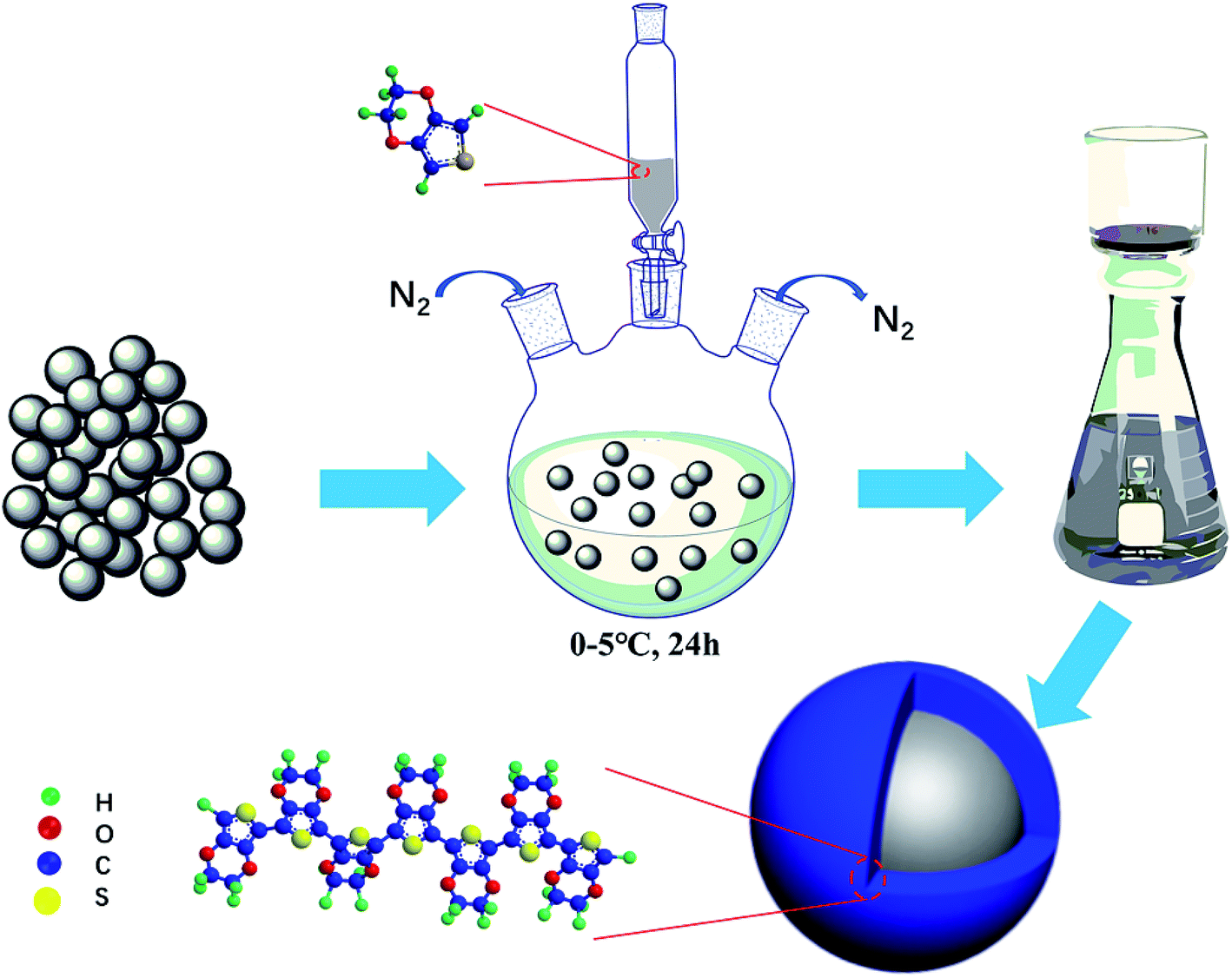 | ||
| Fig. 1 Coating process of PEDOT on LNMO and the facial structure for PEDOT-coated LNMO. | ||
Materials characterization
Thermogravimetric analysis (TGA, TA corporation Q60, heating rate is 10°C min−1) was used to determine the PEDOT content.38–40 The crystal structures and of bare LNMO and PEDOT@LNMO samples were investigated by X-ray diffraction patterns (XRD, Bruk-D8X with Cu Kα) at a scan rate of 2° min−1 from 10° to 80°. The electrical conductivity of the composites was tested by Four-Point Probes (RTS-8, current range: 10 μA, average distance between probes: 1.00 mm). The presence of PEDOT was proved by using FTIR (Bruker, Alpha-P) in the spectral range of 400–4000 cm−1 and 2 cm−1 resolution ratio at room temperature. The morphologies of the samples were observed by scanning electron microscopy (SEM, HITACHI S-4800) and high-resolution transmission electron microscopy (TEM, FEI Tecnai F20). The surface chemical state of the samples was characterized by an X-ray photoelectron spectroscopy (XPS, Thermo Fisher Scientific ESCALAB250). The content of dissolved Mn element after cycles was measured on ICP-MS41Electrochemical measurements
The electrochemical properties of the cathodes were tested by using CR2016 coin cells. The electrode slurries were made by fully mixing 80 wt% active material, 10 wt% super-p, and 10 wt% poly-(vinylidene fluoride) (PVDF) binder in N-methyl pyrrolidone (NMP) solvent. Lithium sheets, 1.2 M LiPF6 in 3:7 ethylene carbonate–ethyl methyl carbonate (v/v), and micro-porous polypropylene film (Celgard 2400) were used as cathode, electrolyte and separator respectively. Cell performance such as cyclability, C-rate capability and discharge capability were characterized by battery test equipment (LAND CT2001A). The coin cells were cycled in the voltage range between 3 V and 4.9 V at 0.2C (1C = 147 mA g−1) at room temperature. The cells were maintained 0.2C rate charging, discharging at 0.2, 0.5, 1, 2, 5, 10C-rate respectively, when testing the rate performance. AC Impedance (EIS) and Cyclic Voltammetry (CV) investigations were estimated on Princeton Versa STAT. the EIS were recorded over the frequency range from 0.01 Hz to 106 Hz. The CV curves were obtained between 3.0 and 4.9 V at scan rate 0.1 mV s−1.
3. Results and discussion
Thermogravimetric curve of the pristine LiNi0.5Mn1.5O4 and all coated samples are shown in Fig. 2(a). The test temperature raised from 50 °C to 700 °C in N2 atmosphere at a heating rate of 10 °C min−1. Compared with pristine LiNi0.5Mn1.5O4, the samples coated with PEDOT show obvious thermal weight loss at 200–530 °C. The weight percentage calculated from the thermogravimetric curves of the coated composites is 1 wt%, 3 wt% and 5 wt%, respectively. Fig. 2(b) shows the XRD pattern of bare sample and PEDOT@LNMO composite materials. As can be seen, the diffraction peaks of the coated samples are similar to the pristine LNMO can be well indexed to the spinel-structured LNMO standard card (space group = Fd3m, PDF#80-2162), indicating the in situ coating of PEDOT did not change the structure of LNMO. To further understand the chemical structure of the coated samples, FTIR spectroscopies were used to characterize the chemical formation on the surface of the PEDOT@LNMO composites. The peaks located at 501 cm−1 and 624 cm−1 in Fig. 2(c) are character to LNMO. For PEDOT, the peak at 849 cm−1 is oxyethylene ring stretching vibration, the characteristic peaks at 1529 cm−1, 1367 cm−1 and 980 cm−1 are the stretching vibration of C![[double bond, length as m-dash]](https://www.rsc.org/images/entities/char_e001.gif) C, C–C and C–S respectively. The C–O–C bond is located at 1090 cm−1, all the characteristic peaks of PEDOT were clearly observed in the spectrum of PEDOT@LNMO composites. Moreover, the peak intensity of the infrared absorption for PEDOT increased with the amount coating on the LNMO. Combined the XRD and FT-IR analyses, we can find that the PEDOT coating did not change the structure of the LNMO and the EDOT was successfully polymerized on the surface of LNMO particles to form PEDOT.42–44
C, C–C and C–S respectively. The C–O–C bond is located at 1090 cm−1, all the characteristic peaks of PEDOT were clearly observed in the spectrum of PEDOT@LNMO composites. Moreover, the peak intensity of the infrared absorption for PEDOT increased with the amount coating on the LNMO. Combined the XRD and FT-IR analyses, we can find that the PEDOT coating did not change the structure of the LNMO and the EDOT was successfully polymerized on the surface of LNMO particles to form PEDOT.42–44
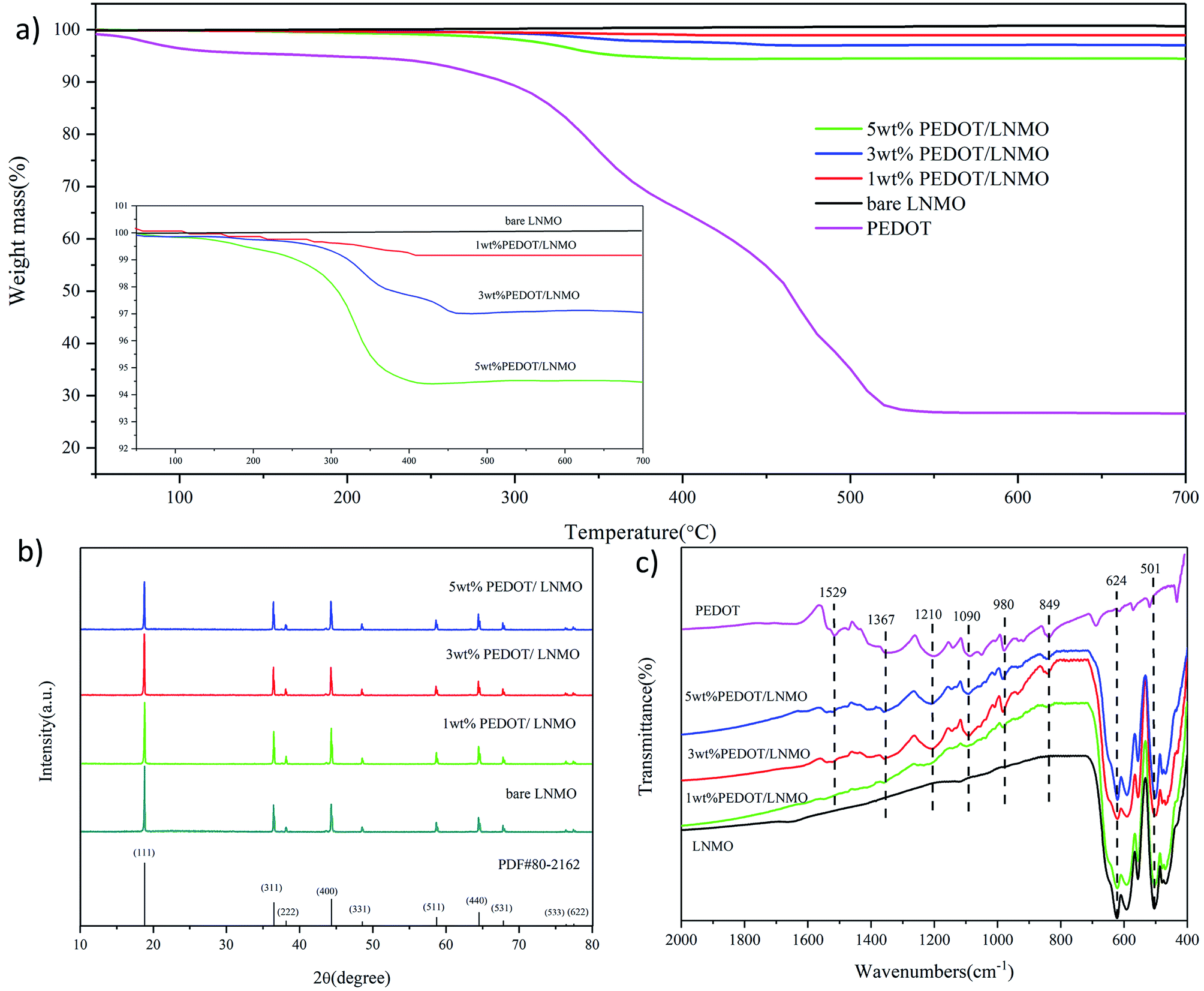 | ||
| Fig. 2 (a) TGA curves, with the inset showing an enlargement of the indicated region, (b) X-ray diffraction patterns, and (c) FT-IR spectra of the samples. | ||
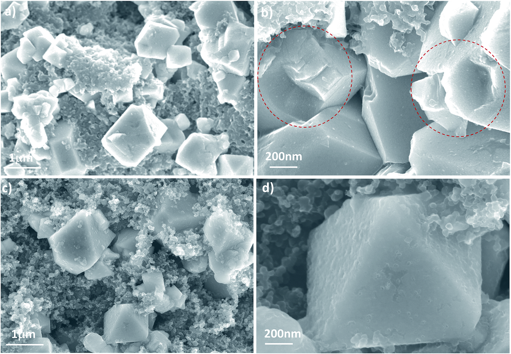
Fig. 3 shows the morphologies of pristine LNMO and PEDOT-coated composites. The image in Fig. 3(a) reveals that the bare sample is composed of uniformly distributed octahedral particles with diameters in the range of 200 nm to 1 μm, smooth facets and sharp edges. When coated by PEDOT (Fig. 3(b–d)), the surface of the coated samples turned rougher and fuzzier. This observation indicates that the surfaces of LNMO are almost fully covered by PEDOT without agglomeration.
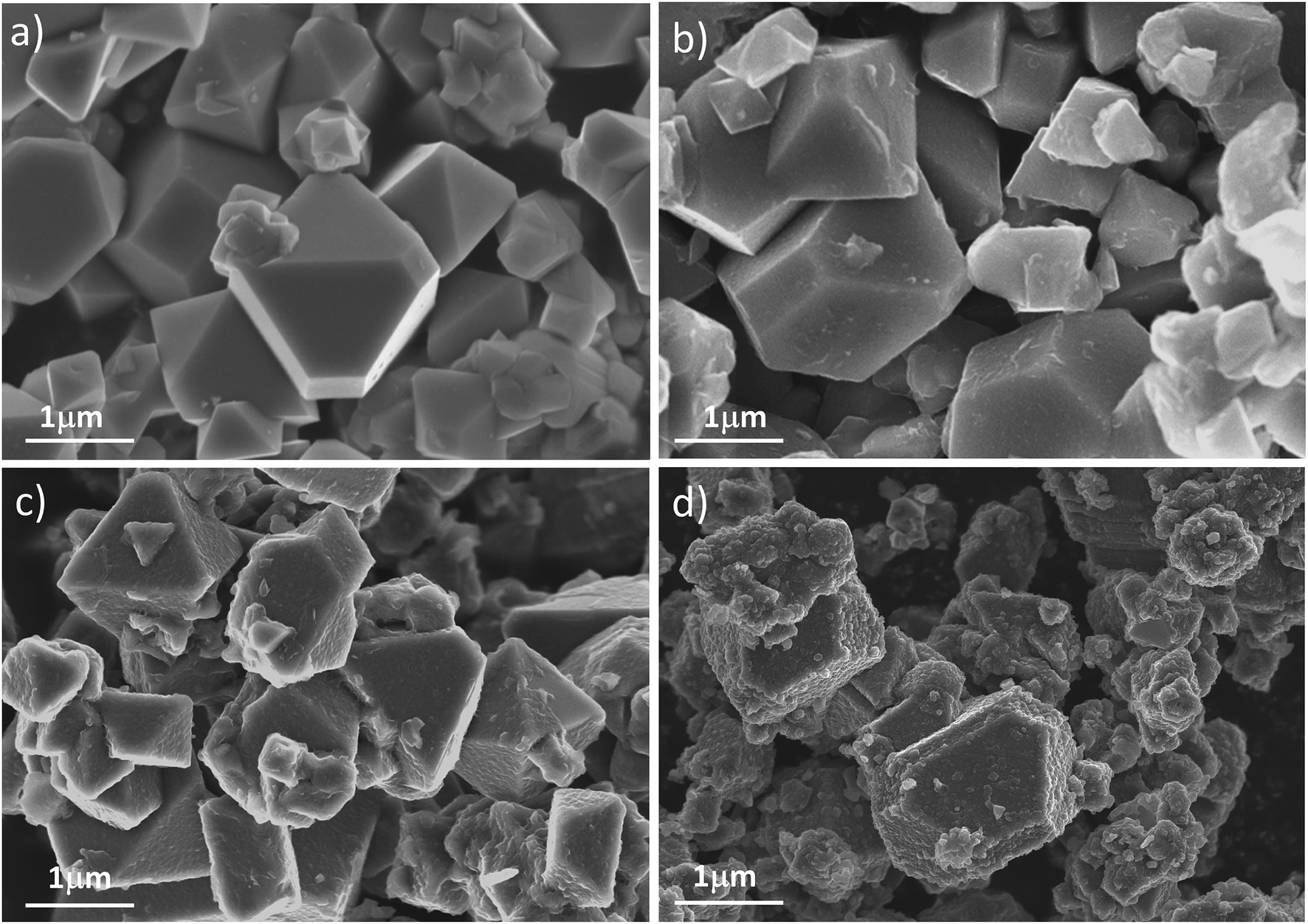 | ||
| Fig. 3 SEM of (a) LNMO, (b) 1% wt% PEDOT@LNMO, (c) 3 wt% PEDOT@LNMO, (d) 5 wt% PEDOT@LNMO. | ||
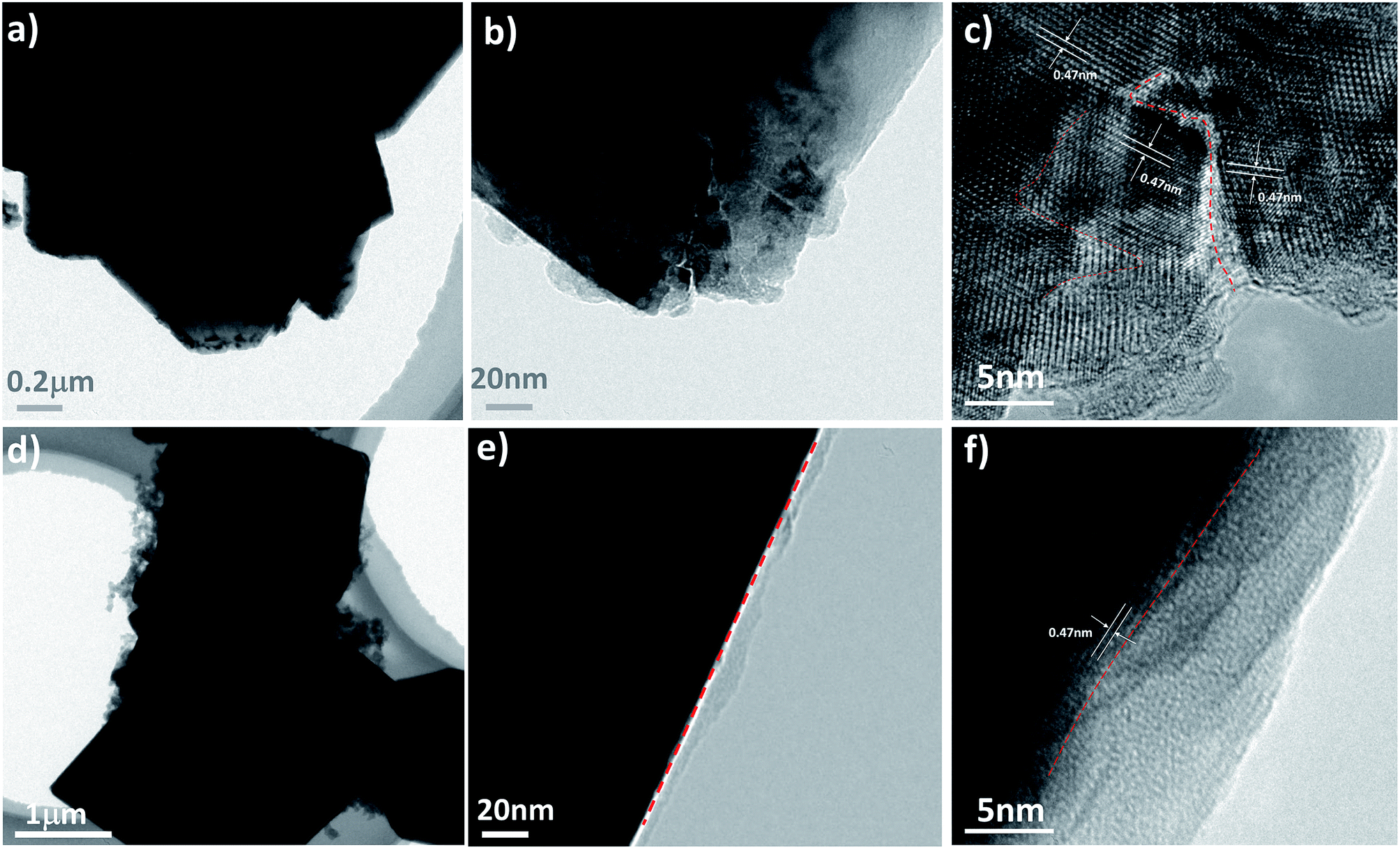
To further confirm the effective coating of PEDOT on the surface of LNMO particles, we also carried out high-resolution TEM characterizations contains TEM image, HR-TEM image and EDS mapping of Mn, Ni, O and S for the 3 wt% coated samples. In Fig. 4(a) and (b), a layer of amorphous PEDOT with thick of 8 nm to 10 nm can be detected, which can be further proved by the mapping map of the well distributed S element. Moreover, Fig. 4(b) directly shows the legible lattice fringes with basal distances of 4.70 Å which are corresponding to the (111) planes of LNMO. This observation is in good agreement with SEM (Fig. 3) results, indicating a uniform PEDOT layer had been coated successfully on surface of the LNMO. Table S1† presented the electrical conductivity of bare and coated LNMO. It can be seen that the electronic conductivity of samples increased from 9.74 × 10⁻⁶ S cm−1 to 7.14 × 10⁻³ S cm−1 with the increase of PEDOT coating. The improved electronic conductivity may attribute to the particular conducted channel build by the PEDOT in composite materials.
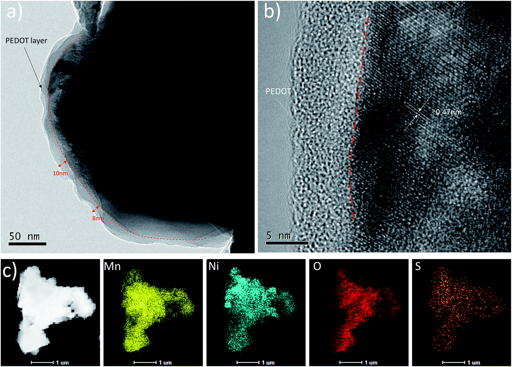 | ||
| Fig. 4 TEM image (a) and HRTEM image (b) and (c) STEM image for the 3 wt% PEDOT@LNMO and the related EDS mapping images of Mn, Ni, O and S elements. | ||
Electrochemical testing of all the samples was conducted at a rate of 0.2C at room temperature in a 3.0–4.9 V window. The voltage versus capacity data for one of these tests is shown in Fig. 5. As can be seen, the bare sample shows a representative profile of spinel LiNi0.5Mn1.5O4 cathode, comprising two obvious stages in the charge curve. The first stage at around 4.70 V and 4.75 V originated from reversible Ni2+/3+ and Ni3+/4+ reactions, while the other one near 4.0 V should be attributed to the transition of Mn3+/4+.45,46 Compared with the bare sample, the PEDOT coated samples exhibited almost the same charge/discharge curves, except for the polarization between charge and discharge. The polarization increased with the increase of PEDOT coating amount during the first cycle. However, the polarizations for coated samples become constant in following cycles, while the bare one shows an increasing polarization. The initial discharge capacities of the bare samples and the 1 wt%, 3 wt% and 5 wt% coated samples are 13.7 mA h g−1, 11.4 mA h g−1, 8.7 mA h g−1 and 5.6 mA h g−1 at 3.0–4.9 V, respectively. The decreased capacity in the first cycle may attributed to activation process of batteries. The cycling performance of four samples indicating that the coating PEDOT can help to enhance cycling stability of spinel core, which is probably due to maintaining crystal structure of the spinel material by the coating PEDOT. Similarly, this phenomenon is more obvious in 5 wt% PEDOT@LNMO in Fig. 5(d). The discharge capacity at the 50th and 100th times is higher than the 10th time, and the 10th discharge capacity is higher than the first time. This may be because the thicker PEDOT layer separates the active material from the electrolyte, the infiltration of electrolyte to porous battery is slowed down. Therefore, the active material could not fully charged-discharged. what's more, 3 wt% PEDOT@LNMO has better electrochemical cycle stability compared to other samples. It is shown that the discharge capacity is 114.5 mA h g−1, and the capacity retention is 91.6% after 200 cycles.
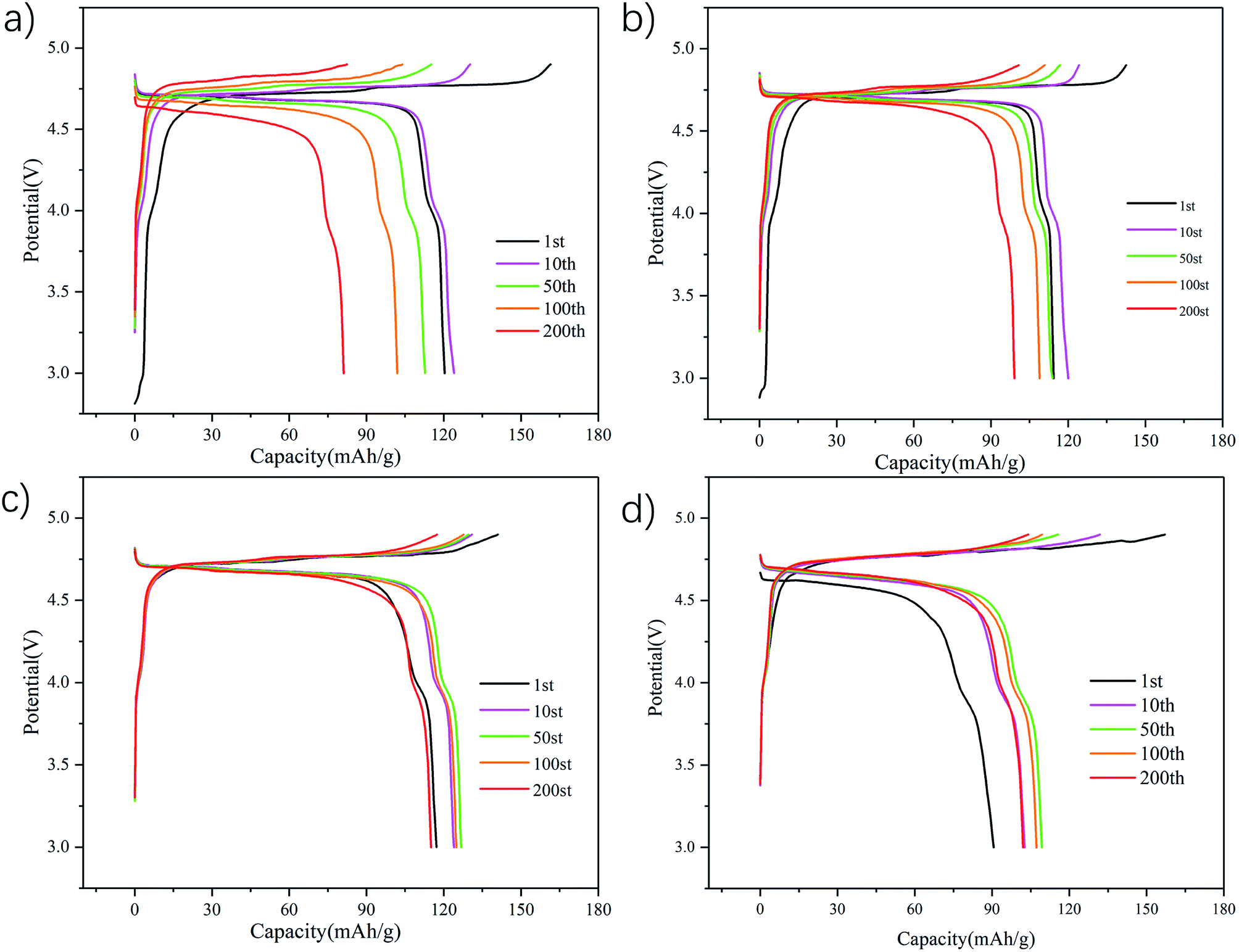 | ||
| Fig. 5 1st, 10th, 100th and 200th cycle charge–discharge curves of (a) bare LNMO, (b) 1 wt% PEDOT@LNMO, (c) 3 wt% PEDOT@LNMO, and (d) 5 wt% PEDOT@LNMO at 0.2C and room temperature (25 °C). | ||
The cycle performances of the pristine and coated materials are investigated with a 0.2C charge–discharge rate (Fig. 6). All the samples show an increasing capacity within few cycles, which can be ascribed to the activate process. The pristine material shows capacity retention of 56.5% after 200 cycles. After PEDOT coating, the capacity retention increased with the coating amount. From Fig. 6(a), the coated samples with various PEDOT balances the obtainable capacity with the cycling stability, thus, it demonstrates the best performance among the samples compared in this work, the 3 wt% PEDOT coating sample revealed capacity retention of 91.6% with a capacity of 114.5 mA h g−1 after 200 cycles, and the coulomb efficiency is very stable and high. However, it has to be pointed out that if the film becomes thicker (as the 5 wt% coated LiNi0.5Mn1.5O4), it would be more difficulty for the electrolyte to infiltrate to porous cathodes to obtain high capacity within initial cycles, further support the protection of dense PEDOT film formed on the surface of LNMO.
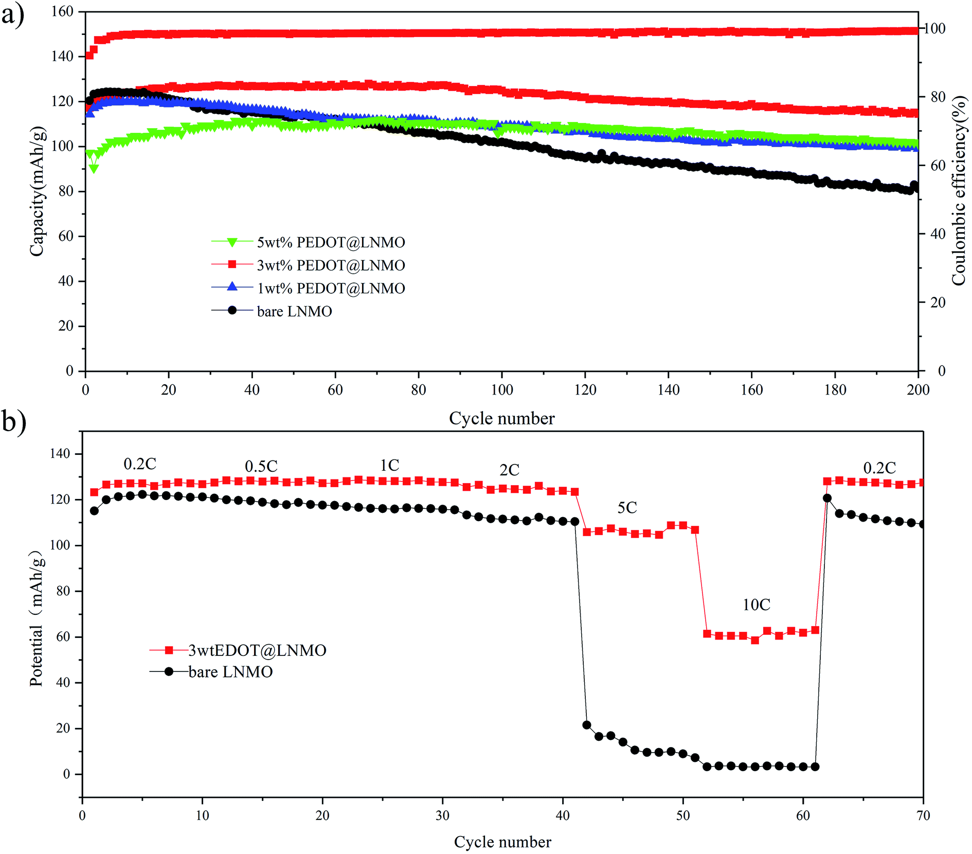 | ||
| Fig. 6 Electrochemical performance of pristine LNMO and PEDOT@LNMO composite (a) cycle life and coulombic efficiency of 3 wt% PEDOT@LNMO, (b) rate performance of LNMO and PEDOT@LNMO composites. | ||
To further evaluate the effect of conductive PEDOT on the electrochemical performance of the PEDOT@LNMO cathodes. The comparisions of bare LNMO and 3 wt% PEDOT@LNMO obtained in the range of 3.0–4.9 V at different discharge rates are shown in the Fig. 6(b). The discharge capacities of coated samples are almostly higher than that of the bare LNMO, especially for cycling at rate of 5C and 10C, the capacity for LNMO were 10 mA h g−1 and close to 0 mA h g−1 respectively, while for the coated sample, they reached to 108 and 63 mA h g−1 respectively. Additionally, when the test rate recovers to 0.2C, the bare LNMO show obviously capacity decay after various rates cycle compared to the coated sample. As a result, PEDOT@LNMO exhibits better rate capability than bare LNMO, indicating the benefits of conductive PEDOT modification.
XRD was used to understand the structure changes of the bare LNMO and 3 wt% PEDOT@LNMO after long-term cycles. As can be seen from the Fig. S1,† (111) peak for pristine LNMO shifts slightly to the high 2-theta, indicated that the decrease of intensity and lattice parameter of the LiNi0.5Mn1.5O4 electrode without PEDOT.47–50 But there is no evident of diffraction peaks shift of the cycled LNMO electrode with PEDOT coating. The diffraction peak shift for the electrode cycled in pristine LNMO is most likely caused by the dissolution of Mn3+ from the bulk structure, which leads to generate the smaller radius of Mn4+ via the disproportionation reaction.51,52 Furthermore, the Rietveld refinement results in Table. S2† presented the lattice parameters are 8.17 Å and 8.15 Å for LNMO before and after cycle, respectively, and the lattice parameters of the 3 wt% PEDOT@LNMO before and after cycle are 8.17 Å and 8.167 Å, respectively. The evolution of the lattice parameter and diffraction peaks shift proved that coating PEDOT on the surface of LNMO can suppress the dissolution of Mn3+ and the shrinkage of the crystal lattice, further supporting the advantages on improving the structure stability.
Microstructural analysis after long-term cycling is presented in Fig. 7 and 8 For LNMO further cycling to 200 cycles leads to the formation of a surface with fragment and micro cracks, while the PEDOT coated sample reveals a much more smoother surface structure similar to the sample before cycling. Furthermore, Fig. 8 shows the typical TEM image of the two cathodes after long-term cycling with micro-scaled fracture identified. With higher magnification in Fig. 8(e) and (f), we see that fracture occurs along the (111) planes. These defects may be ascribed to the dissolution of transition metal ions due to the reaction between electrode and electrolyte and Jahn–Tell crystallographic distortion happen in LiNi0.5Mn1.5O4. In addition, the twisted fringes suggest significant internal stress caused by Jahn–Teller and electrolyte corrosion that result in structural collapse on the micro-scale. Surprisingly, the particle of 3 wt% PEDOT@LNMO maintains its structure integrity possibly ascribe to the protective film formed by in situ synthetic method.
 | ||
| Fig. 7 (a and b) SEM images at different magnification of pristine LNMO, and (c and d) 3 wt% PEDOT@LNMO after 200 cycles. | ||
 | ||
| Fig. 8 (a–c) TEM and HRTEM images at different magnification of pristine LNMO, and (d–f) 3 wt% PEDOT@LNMO after 200 cycles. | ||
Fig. S2† displays the impedance spectra of pristine LNMO and the coated sample collected at initial and 200 cycles. The isolated domains should lead to an increase of the internal resistance in. The equivalent circuit was applied to describe the profiles. Rs represents the solution resistance, and the diameter of the semi-circle gives the charge transfer resistance as Rct.53 As can be seen, the lower Rs and Rct for electrode of PEDOT coated LNMO may attribute to outstanding electrical conductivity. In comparison with the freshly prepared cell, there is a large increase in both Rs and Rct values as 4.811 Ω and 226.59 Ω which is consistent with Table. S3† for bare LNMO. At the same cycle, the coated LNMO possess obviously lower interface resistance and surface charge transfer resistance compared to the comparative LNMO, indicating of more stable structure. Although the impedances increase with cycle numbers for all spinel samples, the coated LNMO electrode shows relatively less enlargement as 1.583 Ω and 116.7 Ω, which is consistent with its better capacity retention and particular rate capability and further indicates the advantages of PEDOT@LNMO.
The lithium ion diffusion coefficient (DLi) was calculated from the EIS spectra in the low frequency region by the follow equations:54–56
| Zre = Rs + Rct + σω−1/2 | (1) |
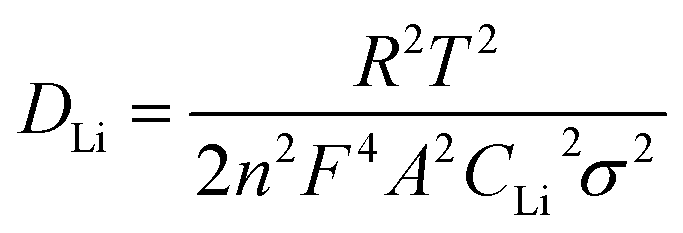 | (2) |
As described in the XRD analysis about the evolution of the structure in long-term cycles, the XPS spectra for Mn 2p at various cycles of bare and coated samples were presented in Fig. 9. As shown in the Mn 2p spectra, the bonding energies of 654 eV and 642.5 eV for the cycled samples, which can be assigned to Mn 2p1/2 and Mn 2p3/2 are changed obviously as compared to those of the bare samples, indicating the evolution of Mn valence state. In order to obtain detailed information about the valence state of Mn in different states, the curve fitting of Mn 2p3/2 spectra was carried out.57 The results shown in the Fig. 9(b–d) indicating the percentage of Mn4+, Mn3+ and Mn2+ in pristine LNMO are 68.6%, 29.9% and 1.5% (Fig. 9(b)). After 200 cycles, the proportion of Mn4+ and Mn2+ increased to 81.5% and 3.3%, respectively, while the percentage of Mn3+ decreased to 15.2%. It has been reported that the evolution of the Mn valence was caused by the disproportion reaction. On the contrary, the Mn valence for 3 wt% PEDOT@LNMO changes less. The disproportion reaction can be further support by the ICP results shown in Table. S4.† For cycled LNMO electrode, Mn in the solution is 1.274 mg L−1 which is calculated to be 0.0636 mg. The electrode prepared in the test contains 1.8 g LNMO, thus the dissolution percentage is close to 3.538%. Fortunately, the dissolution of Mn was inhibited by adopting PEDOT coating for it is only 1.2% of Mn dissolute in the electrolyte for 3 wt% PEDOT@LNMO after 200 cycles. These results further proved that the PEDOT coating on the surface of LNMO can greatly enhance the stability of the interface between cathode and electrolyte thus inhibited the dissolution of Mn. Moreover, the inter structure stability is significant improved with the improvement of the surface structure stability during long term cycling.
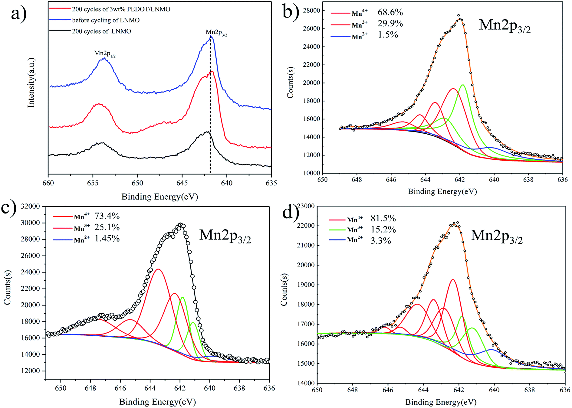 | ||
| Fig. 9 (a) Mn 2p spectra for LNMO at different states (pristine LNMO before cycling, pristine LNMO after 200 cycles, 3 wt% PEDOT@LNMO after 200 cycles), fitted spectra of (b) pristine LNMO before cycling, (c) pristine LNMO after 200 cycles, (d) 3 wt% PEDOT@LNMO after 200 cycles. | ||
4. Conclusions
In summary, an innovative method of in situ polymerize PEDOT on the surface of LNMO to improve the electrochemical performance has been demonstrated. The uniform and dense PEDOT layer on the surface of LNMO work as a conductive and protective structure, ensured better cycle stability and rate performance compared to the bare sample. An electrode made with 3 wt% PEDOT@LNMO delivered a stable output capacity of 114 mA h g−1 with a capacity retention of 91.6%, which was mainly ascribed to the limitation of disproportion reaction and decrease of the Mn dissolution, as these side reactions would possibly lead to collapse of the surface structure and the shrinkage of the crystal lattice in cathodes. Moreover, the PEDOT coated material exhibited excellent rate performance of 110 mA h g−1 and 63 mA h g−1 at 5C and 10C rate respectively due to the high electrical conductivity. The enhanced performance is due to the reasonable design in stable the surface structure of the material, which suggests that the approach of inorganic/polymer compositions will be very helpful in the industrialization development of advanced Ni–Mn-spinel LiNi0.5Mn1.5O4 cathode materials with long cycle life at high voltage for high-energy density lithium ion batteries.Conflicts of interest
There are no conflicts to declare.Acknowledgements
The authors acknowledge the financial support from the National Natural Science Foundation of China (grant No. 21875282), Hunan Provincial Natural Science Foundation (grant No. 2018JJ3595) and China Postdoctoral Science Foundation funded project (2018M633664).References
- C.-Y. Wang, G. Zhang, S. Ge, T. Xu, Y. Ji, X.-G. Yang and Y. Leng, Nature, 2016, 529, 515–518 CrossRef CAS PubMed.
- K. Liu, Y. Liu, D. Lin, A. Pei and Y. Cui, Sci. Adv., 2018, 4, eaas9820 CrossRef PubMed.
- M. Li, J. Lu, Z. Chen and K. Amine, Adv. Mater., 2018, 30, 1800561 CrossRef PubMed.
- X. Chen and Y. Ma, Adv. Mater. Technol., 2018, 0, 1800041 CrossRef.
- J. Lee, D. A. Kitchaev, D.-H. Kwon, C.-W. Lee, J. K. Papp, Y.-S. Liu, Z. Lun, R. J. Clément, T. Shi, B. D. McCloskey, J. Guo, M. Balasubramanian and G. Ceder, Nature, 2018, 556, 185–190 CrossRef CAS PubMed.
- Y. Chen, Z. Chen and K. Xie, J. Phys. Chem. C, 2014, 118, 11505–11511 CrossRef CAS.
- S. Panchal, J. Mcgrory, J. Kong, R. Fraser, M. Fowler, I. Dincer and M. Agelin-Chaab, Int. J. Energy Res., 2017, 41, 2565–2575 CrossRef CAS.
- Z. Li, H. Zhao, P. Lv, Z. Zhang, Y. Zhang, Z. Du, Y. Teng, L. Zhao and Z. Zhu, Adv. Funct. Mater., 2018, 28, 1605711 CrossRef.
- H. Qiu, Y. Wang and S. Ye, Energy Technol., 2018, 6, 201800415 Search PubMed.
- H. Z. Zhang, Q. Q. Qiao, G. R. Li and X. P. Gao, J. Mater. Chem. A, 2014, 2, 7454–7460 RSC.
- C.-C. Su, M. He, P. C. Redfern, L. A. Curtiss, I. A. Shkrob and Z. Zhang, Energy Environ. Sci., 2017, 10, 900–904 RSC.
- W. Sun, Y. Li, Y. Liu, Q. Guo, S. Luo, J. Yang, C. Zheng and K. Xie, J. Mater. Chem. A, 2018, 6, 14155–14161 RSC.
- G. Xu, C. Pang, B. Chen, J. Ma, X. Wang, J. Chai, Q. Wang, W. An, X. Zhou, G. Cui and L. Chen, Adv. Energy Mater., 2018, 8, 1870038 CrossRef.
- J. Wang, P. Nie, J. Jiang, Y. Wu, R. Fu, G. Xu, Y. Zhang, H. Dou and X. Zhang, ChemElectroChem, 2018, 5, 1212–1218 CrossRef CAS.
- S. Deng, B. Xiao, B. Wang, X. Li, K. Kaliyappan, Y. Zhao, A. Lushington, R. Li, T.-K. Sham, H. Wang and X. Sun, Nano Energy, 2017, 38, 19–27 CrossRef CAS.
- J. Li, L. Baggetto, S. K. Martha, G. M. Veith, J. Nanda, C. Liang and N. J. Dudney, Adv. Energy Mater., 2013, 3, 1275–1278 CrossRef CAS.
- P. Nie, L. Shen, H. Luo, B. Ding, G. Xu, J. Wang and X. Zhang, J. Mater. Chem. A, 2014, 2, 5852–5857 RSC.
- Y. Ma, K. Chen, J. Ma, G. Xu, S. Dong, B. Chen, J. Li, Z. Chen, X. Zhou and G. Cui, Energy Environ. Sci., 2019, 12, 273–280 RSC.
- L. Xiao, J. Xiao, X. Yu, P. Yan, J. Zheng, M. Engelhard, P. Bhattacharya, C. Wang, X.-Q. Yang and J.-G. Zhang, Nano Energy, 2015, 16, 143–151 CrossRef CAS.
- B. Xiao, H. Liu, J. Liu, Q. Sun, B. Wang, K. Kaliyappan, Y. Zhao, M. N. Banis, Y. Liu, R. Li, T.-K. Sham, G. A. Botton, M. Cai and X. Sun, Adv. Mater., 2017, 29, 1703764 CrossRef PubMed.
- J.-H. Cho, J.-H. Park, M.-H. Lee, H.-K. Song and S.-Y. Lee, Energy Environ. Sci., 2012, 5, 7124–7131 RSC.
- J. Mou, Y. Deng, Z. Song, Q. Zheng, K. H. Lam and D. Lin, Dalton Trans., 2018, 47, 7020–7028 RSC.
- S. Tao, F. Kong, C. Wu, X. Su, T. Xiang, S. Chen, H. Hou, L. Zhang, Y. Fang, Z. Wang, W. Chu, B. Qian and L. Song, J. Alloys Compd., 2017, 705, 413–419 CrossRef CAS.
- W. Liu, Q. Shi, Q. Qu, T. Gao, G. Zhu, J. Shao and H. Zheng, J. Mater. Chem. A, 2017, 5, 145–154 RSC.
- J. Ma, P. Hu, G. Cui and L. Chen, ChemInform, 2016, 11, 3578–3606 Search PubMed.
- J. Ma, P. Hu, G. Cui and L. Chen, Chem. Mater., 2016, 28, 3578–3606 CrossRef CAS.
- H. Zhang, C. Mao, J. Li and R. Chen, RSC Adv., 2017, 7, 33789–33811 RSC.
- Y. Wang, Q. Peng, G. Yang, Z. Yang, L. Zhang, H. Long, Y. Huang and P. Lu, Electrochim. Acta, 2014, 136, 450–456 CrossRef CAS.
- J. Wang, S. Yao, Y. Yu, T. Fu, P. Zhang and J. Zhao, Electrochim. Acta, 2016, 208, 310–317 CrossRef CAS.
- Q. Wu, X. Zhang, S. Sun, N. Wan, D. Pan, Y. Bai, H. Zhu, Y. S. Hu and S. Dai, Nanoscale, 2015, 7, 15609 RSC.
- Q. Wu, Y. Yin, S. Sun, X. Zhang, N. Wan and Y. Bai, Electrochim. Acta, 2015, 158, 73–80 CrossRef CAS.
- Y. Y. Huang, X. L. Zeng, C. Zhou, P. Wu and D. G. Tong, J. Mater. Sci., 2013, 48, 625–635 CrossRef CAS.
- T.-F. Yi, Y.-M. Li, X.-Y. Li, J.-J. Pan, Q. Zhang and Y.-R. Zhu, Science Bulletin, 2017, 62, 1004–1010 CrossRef CAS.
- X. Xu, S. Deng, H. Wang, J. Liu and H. Yan, Nano-Micro Lett., 2017, 9, 22 CrossRef PubMed.
- X. W. Gao, Y. F. Deng, D. Wexler, G. H. Chen, S. L. Chou, H. K. Liu, Z. C. Shi and J. Z. Wang, J. Mater. Chem. A, 2014, 3, 404–411 RSC.
- X. Wang, L. Shen, H. Li, J. Wang, H. Dou and X. Zhang, Electrochim. Acta, 2014, 129, 283–289 CrossRef CAS.
- J. Kim, J. K. Yoo, Y. S. Jung and K. Kang, Adv. Energy Mater., 2013, 3, 1004–1007 CrossRef CAS.
- Y. Liu, D. Tang, H. Zhong, Q. Zhang, J. Yang and L. Zhang, RSC Adv., 2016, 6, 95512–95517 RSC.
- S. Zhang and R. Hu, Mater. Lett., 2016, 176, 131–134 CrossRef CAS.
- I.-H. Ko, S.-J. Kim, J. Lim, S.-H. Yu, J. Ahn, J.-K. Lee and Y.-E. Sung, Electrochim. Acta, 2016, 187, 340–347 CrossRef CAS.
- Y. Zhu, X. Luo, M. Xu, L. Zhang, L. Yu, W. Fan and W. Li, J. Power Sources, 2016, 317, 65–73 CrossRef CAS.
- L. Yue, S. Wang, X. Zhao and L. Zhang, J. Mater. Chem., 2011, 22, 1094–1099 RSC.
- M. Salsamendi, R. Marcilla, M. Döbbelin, D. Mecerreyes, C. Pozo-Gonzalo, J. A. Pomposo and R. Pacios, Phys. Status Solidi, 2010, 205, 1451–1454 CrossRef.
- L. Yue, S. Wang, X. Zhao and L. Zhang, J. Mater. Chem., 2012, 22, 1094–1099 RSC.
- J.-H. Cho, J.-H. Park, M.-H. Lee, H.-K. Song and S.-Y. Lee, Energy Environ. Sci., 2012, 5, 7124 RSC.
- F. Wang, L. Suo, Y. Liang, C. Yang, F. Han, T. Gao, W. Sun and C. Wang, Adv. Energy Mater., 2017, 7, 1600922 CrossRef.
- H. Rong, M. Xu, L. Xing and W. Li, J. Power Sources, 2014, 261, 148–155 CrossRef CAS.
- B. Li, Y. Wang, H. Rong, Y. Wang, J. Liu, L. Xing, M. Xu and W. Li, J. Mater. Chem. A, 2013, 1, 12954 RSC.
- B. Chen, L. Ben, Y. Chen, H. Yu, H. Zhang, W. Zhao and X. Huang, Chem. Mater., 2018, 30, 2174–2182 CrossRef CAS.
- Y. Chen, Y. Cheng, J. Li, M. Feygenson, W. T. Heller, C. Liang and K. An, Adv. Energy Mater., 2017, 7, 1601950 CrossRef.
- G. G. Amatucci, C. N. Schmutz, A. Blyr, C. Sigala, A. S. Gozdz, D. Larcher and J. M. Tarascon, J. Power Sources, 1997, 69, 11–25 CrossRef CAS.
- S. Komaba, N. Kumagai, T. Sasaki and Y. Miki, Electrochemistry, 2001, 69, 784–787 CAS.
- Z. Chen, L. Cao, L. Chen, H. Zhou, C. Zheng, K. Xie and Y. Kuang, J. Power Sources, 2015, 298, 355–362 CrossRef CAS.
- T. F. Yi, Y. Xie, Y. R. Zhu, R. S. Zhu and M. F. Ye, J. Power Sources, 2012, 211, 59–65 CrossRef CAS.
- X. Li, W. Guo, Y. Liu, W. He and Z. Xiao, Electrochim. Acta, 2014, 116, 278–283 CrossRef CAS.
- J. Mou, Y. Deng, Z. Song, Q. Zheng, K. H. Lam and D. Lin, Dalton Trans., 2018, 47, 7020 RSC.
- D. Tang, Y. Sun, Z. Yang, L. Ben, L. Gu and X. Huang, Chem. Mater., 2014, 26, 3535–3543 CrossRef CAS.
Footnote |
| † Electronic supplementary information (ESI) available. See DOI: 10.1039/c8ra09550g |
| This journal is © The Royal Society of Chemistry 2019 |