DOI:
10.1039/C8RA09407A
(Paper)
RSC Adv., 2019,
9, 3436-3442
Nb-doped and Al2O3 + B2O3-coated granular secondary LiMn2O4 particles as cathode materials for lithium-ion batteries
Received
15th November 2018
, Accepted 10th January 2019
First published on 25th January 2019
Abstract
In this work, to improve the cyclability and high-temperature performance of cubic spinel LiMn2O4 (LMO) as cathode materials, Nb5+-doped LiMn2O4 powders coated and uncoated with Al2O3 and/or B2O3 were synthesized via the modified solid-state reaction method. It was found that Nb5+-doped and B2O3 + Al2O3-coated LMO powders comprising 5 μm granular agglomerated fine primary particles smaller than 350 nm in diameter exhibited superior electrochemical properties with initial discharge capacity of 101.68 mA h g−1; we also observed capacity retention of 96.31% after 300 cycles at room temperature (RT) and that of 98% after 50 cycles at 55 °C and 1C rate.
1. Introduction
Lithium-ion batteries (LIBs) have widespread applications in consumer electronic devices and potential applications in electric vehicles and hybrid electric vehicles on account of their high operating voltage and high energy density.1–3 To date, a variety of electrode materials have been developed.4–9 LiCO2 and LiFePO4 are the most widely used cathode materials in commercial LIBs because of their good cycle life (>500 cycles); however, they have several drawbacks such as high cost, toxicity of Co for LiCoO2, poor electronic and ionic conductivity, relatively low specific capacity and one-dimensional channels for lithium-ion diffusion for LiFPO4.10 In this context, cubic spinel LiMn2O4 (LMO) as a cathode material has attracted continuous and considerable attention owing to its low cost, natural abundant resources of manganese, high safety, facile 3D Li+-ion diffusion pathways, and nontoxicity. However, the cycling performance of LMO degrades rapidly due to the Jahn–Teller distortion associated with high-spin Mn3+, dissolution of manganese into the electrolyte and undesirable electrode–electrolyte reaction, particularly at elevated temperatures (55 °C), which seriously restrict its application in commercial LIBs.11–13
Various strategies have been attempted to solve these issues, and these mainly include surface coating, doping and morphology control.14–22 Coating LMO particles with metal oxides or fluorides can improve their cycling performance and rate capability by decreasing the contact area between the electrolyte and electrode materials, therefore reducing Mn dissolution.14–17 Furthermore, ion doping of Nb, Al and Ni, respectively or collectively, can induce the formation of a high concentration of Mn4+ ions on the surface of LMO, thereby suppressing the John–Teller distortion and eventually improving cycling stability.18–20 Moreover, the morphology of LMO particles has also been found to be a key factor in determining its electrochemical properties, for example, to study how spherical LMO exhibits better performance than polyhedral LMO.21,22 Hence, it is reasonably expected that through morphology control, coating and doping simultaneously, the electrochemical performance of LMO can be improved to a larger extent. Unfortunately, to the best of our knowledge, studies on their synergetic effects have not been reported so far.
In this work, Nb-doped LMO powders coated with Al2O3 and B2O3 were synthesized through a modified solid-state reaction. The effects of particle morphology, doping and coating on the electrochemical properties of LMO were investigated in detail.
2. Experimental
2.1 Material preparation
Four kinds of LMO samples were synthesized by a modified solid-state reaction. Stoichiometric amounts of Li2CO3, manganese oxides (MnO2 or MnO2 + MnO + Mn3O4) and Nb2O5 were mixed homogeneously by ball milling. Then, the resulting mixtures were sintered at 450 °C for 5 h and 780 °C for 20 h subsequently to obtain Nb-doped LMO. Thereafter, the mixtures were ground, mixed with Al(OH)3 and/or B2O3, and sintered at 750 °C for 10 h. The selected sintering temperature was 750 °C, which is higher than the melting point of Al(OH)3 and B2O3; therefore, the mixture of liquid Al(OH)3 and B2O3 with Nb-doped LMO facilitated the formation of a thin surface layer on LMO particles. The whole synthesis process is depicted in the following equations.23–27 The final obtained materials were labelled as LMOA, LMOB, LMOC and LMOD, as specified in Table 1.| | |
8MnO2 + 2Li2CO3 → 4LiMn2O4 + 2CO2 + O2
| (1) |
| | |
8Mn3O4 + 8MnO2 + 8MnO + 10Li2CO3 + 7O2 → 20LiMn2O4 + 10CO2
| (2) |
| | |
Al(OH)3 (S) → Al(OH)3 (L) (Tm = 300 °C)
| (3) |
| | |
2Al(OH)3 → Al2O3 + 3H2O (G) (Tm = 520 °C)
| (4) |
| | |
B2O3 (S) → B2O3 (L) (Tm = 450 °C)
| (5) |
Table 1 The specific components of the LiMn2O4 samples
| Sample |
Mn oxides |
Li source |
Li![[thin space (1/6-em)]](https://www.rsc.org/images/entities/char_2009.gif) :Mn :Mn |
Nb:Mn |
Coating |
| LMOA |
MnO2 |
Li2CO3 |
1.05:2 |
0.02:1.98 |
— |
| LMOB |
MnO2 |
Li2CO3 |
1.05:2 |
0.02:1.98 |
0.2 mol% Al2O3 |
| LMOC |
MnO2 |
Li2CO3 |
1.05:2 |
0.02:1.98 |
0.2 mol% Al2O3 + 0.1 mol% B2O3 |
| LMOD |
85Mn3O4 + 10MnO2 + 5MnO (wt%) |
Li2CO3 |
1.05:2 |
0.02:1.98 |
0.2 mol% Al2O3 + 0.1 mol% B2O3 |
2.2 Material characterization
The crystal structure of all samples was characterized by the X-ray diffraction (XRD) technique using a Rigaku SmartLab diffractometer with Cu Kα radiation (40 KV, 250 mA) in the range of 10–90° with a step size of 0.02° s−1. Lattice parameters of the as-prepared samples were acquired using the Jade 6.0 refinement software. The morphology and elemental composition were characterized by scanning electron microscopy equipped with EDS (SEM, S-3400N).
2.3 Electrochemical test
An organic-based slurry was prepared via mixing active materials, carbon black, and poly(vinyl difluoride) (PVDF) at a weight ratio of 80:10:10 in the N-methyl-2-pyrrolidone (NMP) solvent. The formed slurry was pasted on an aluminum foil and then dried at 120 °C for 12 h in a vacuum oven. The prepared electrodes were punched into ∅ 12 mm disks and used as the working electrode thereafter. The loading mass density of the active material was about 8 mg cm−2. CR2032 type coin cells were assembled in an argon-filled glove box with a lithium metal foil (Aldrich) as the counter electrode, Whatman filter paper (Alfa Aesar) as the separator, and 1 M LiPF6 in EC/DMC/EMC (1:1:1 by volume) (Alfa Aesar) as the electrolyte. The cycling test was performed by using a Neware battery tester within the voltage range of 3.0–4.2 V vs. Li+/Li under the galvanostatic mode at different current densities (1C = 110 mA g−1) at RT or 55 °C, respectively. Electrochemical impedance spectroscopy (EIS) measurement was carried out on a Chenhua CHI600E workstation between 106 and 10−2 Hz with amplitude of 10 mV.
3. Results and discussion
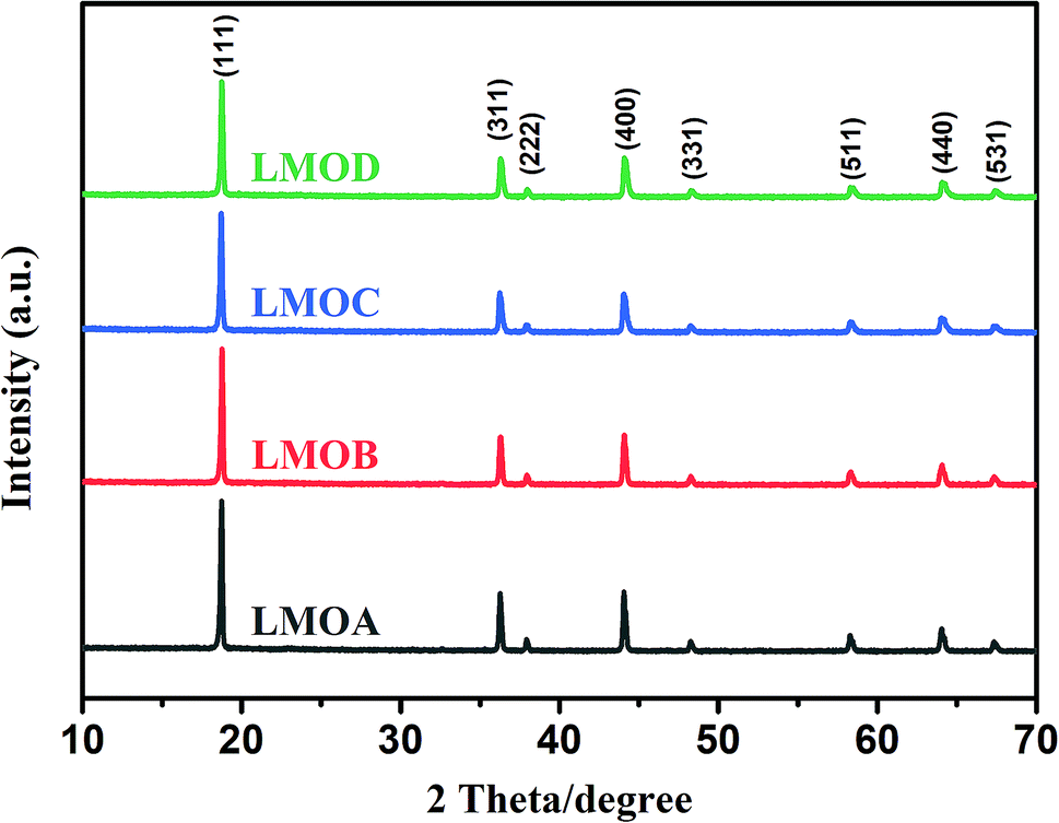
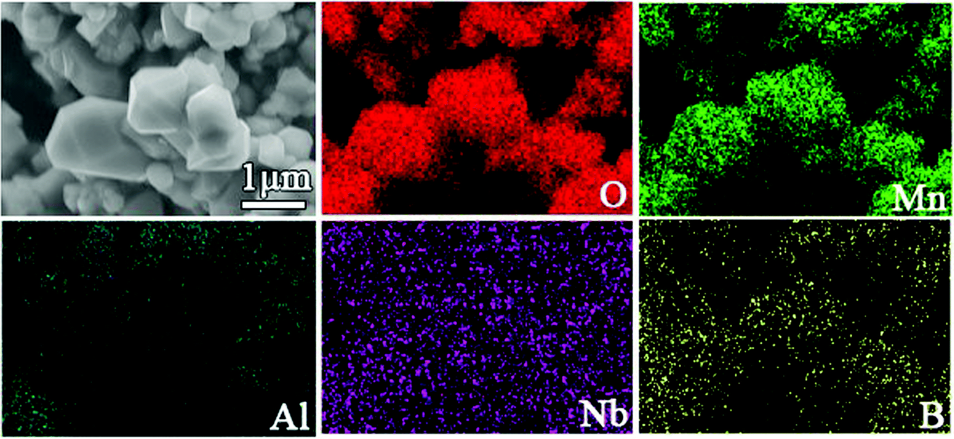
Fig. 1 displays the XRD patterns of Nb-doped LiMn2O4 with and without Al2O3 or Al2O3 + B2O3 coating. All the XRD patterns of the four samples matched well with those of single-phase spinel LiMn2O4; distinct diffraction peaks were observed from the (111), (311) and (400) crystal planes and relatively weak peaks were observed from the (222), (331), (511), (440), and (531) planes.5,28 No peaks of impurities were observed after doping and coating, which indicated that both B2O3 and Al2O3 layers existed in the amorphous state. Fig. 2 shows the SEM images of all samples. Nb-doped LiMn2O4 with MnO2 as the Mn source and without the coating (LMOA) consisted of polygon- or pyramid-type particles of about 500 nm to few microns in diameter, with quite clean and smooth edges. After B2O3 coating (LMOB) or B2O3 + Al2O3 coating (LMOC) through sintering at 750 °C for 10 h, the edges of all the particles were passivated and obscure. However, their particle sizes exhibited different behaviors: significant increase for the sample LMOB with Al2O3 coating and almost no change for the sample LMOC with B2O3 + Al2O3 coating; this indicated the beneficial effect of the liquid B2O3 layer on suppressing the particle growth during sintering at 750 °C for 10 h. The EDS elemental mapping of O, Mn, Al, Nb and B in the selected area of sample LMOC (Fig. 3) revealed that Al and B are homogeneously coated on LMO microspheres. In contrast, the sample LMOD with the mixture of MnO, MnO2 and Mn3O4 as Mn sources and B2O3 + Al2O3 as the coating consisted of granular secondary particles of about 5 microns in diameter, which comprised fine primary particles (smaller than about 350 nm in size) with obscure edges.
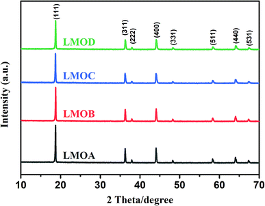 |
| | Fig. 1 XRD patterns of different LiMn2O4 samples: LMOA, LMOB, LMOC, LMOD. | |
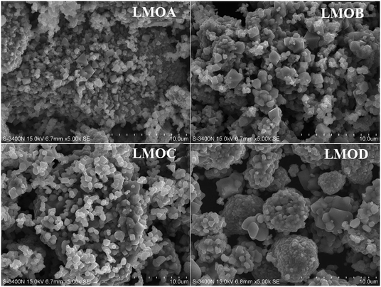 |
| | Fig. 2 SEM images of different LiMn2O4 samples: LMOA, LMOB, LMOC, LMOD. | |
 |
| | Fig. 3 EDS mappings of the selected area in sample LMOC. | |
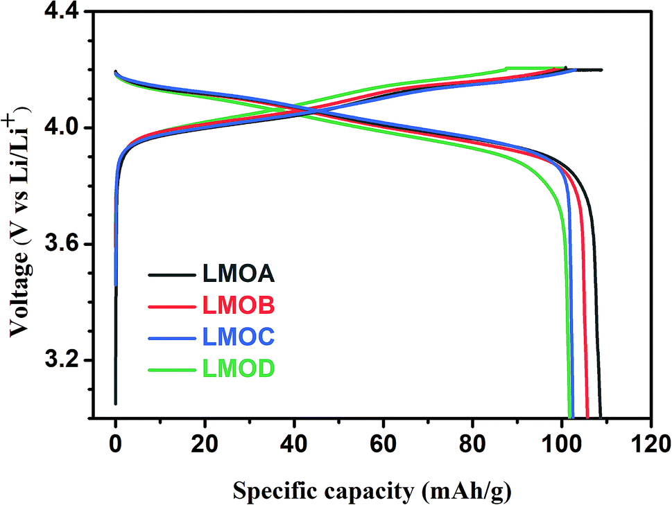
Fig. 4 shows the initial charge–discharge curves of all four samples at 1.0C rate in the voltage range of 3.0–4.2 V. It can be clearly seen that all samples exhibited similar voltage profiles in the initial discharge processes with two voltage plateaus at 4.0 V and 4.1 V, which were ascribed to the step-by-step Li+-ion deintercalation from the host oxide, as shown in eqn (6) and (7).29,30 The initial discharge capacities of LMOA, LMOB, LMOC and LMOD were 109 mA h g−1, 106 mA h g−1, 102 mA h g−1 and 102 mA h g−1, respectively, showing a decreasing trend with increasing coating content due to the inactive nature of these coatings toward Li+ ions.
| | |
LiMn2O4 → Li1−xMn2O4 + xLi+xe−, (x < 0.5)
| (6) |
| | |
Li1−xMn2O4 → Mn2O4 + (1 − x)Li+(1 − x)e−, (x ≥ 0.5)
| (7) |
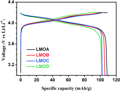 |
| | Fig. 4 The initial charge–discharge curves of LMOA, LMOB, LMOC and LMOD. | |
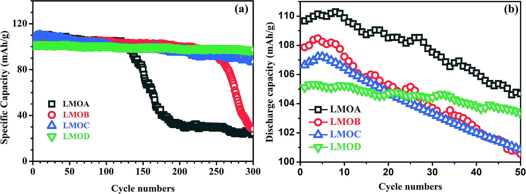
Fig. 5 shows the cycling stability of all samples at a current density of 1.0C between 3.0 and 4.2 V at 25 °C and 55 °C. At 25 °C (Fig. 5a), the Nb-doped and uncoated LiMn2O4 (LMOA) exhibited significant capacity fading with cycling; the specific discharge capacity quickly decreased to around 30 mA h g−1 after 130 cycles. After Al2O3 coating or Al2O3 + B2O3 coating, respectively, the cycling stability of Nb-doped LiMn2O4 could be improved significantly but was still not completely satisfactory, especially in the case of Al2O3 coating (LMOB), for which rapid capacity fading was observed after 230 cycles. By contrast, the sample LMOD, consisting of spherical secondary particles and with Al2O3 + B2O3 coating, displayed excellent cycling stability with capacity retention as high as 96.31% after the 300th cycle. At an elevated temperature of 55 °C, the cycling stability of all samples was measured at 1.0C between 3.0 and 4.2 V (Fig. 5b). After 50 cycles, the capacity retention values of samples LMOA, LMOB, LMOC and LMOD were 95.40%, 93.25%, 94.57% and 97.98%, respectively. The superior cycling stability of sample LMOD to that of others could be attributed to their different morphologies because of the use of different manganese oxides as raw materials since all the other factors including Li/Mo ratio, crystal structure, Nb content and their coating composition were completely identical. Furthermore, by comparison with the reported results illustrated in Table 3, it could be seen that our Al2O3 + B2O3-coated and Nb-doped granular LMO secondary particles exhibited much better cycling stability at both 25 °C and 55 °C than pure LMO,19,31,32 Al(Mg, Ce, Ni, Mn, Nb)-doped LMO,12,18,19,31,33 and AlF3(La–Sr–Mn–O, V2O5, ZrO2)-coated LMO, indicating the synergetically beneficial effect of doping, coating, and special morphology of granular secondary particles in our work.
 |
| | Fig. 5 The cycling performances of LMOA, LMOB, LMOC and LMOD at 25 °C (a) and at 55 °C (b) at a current density of 1C. | |
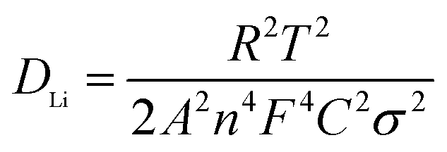
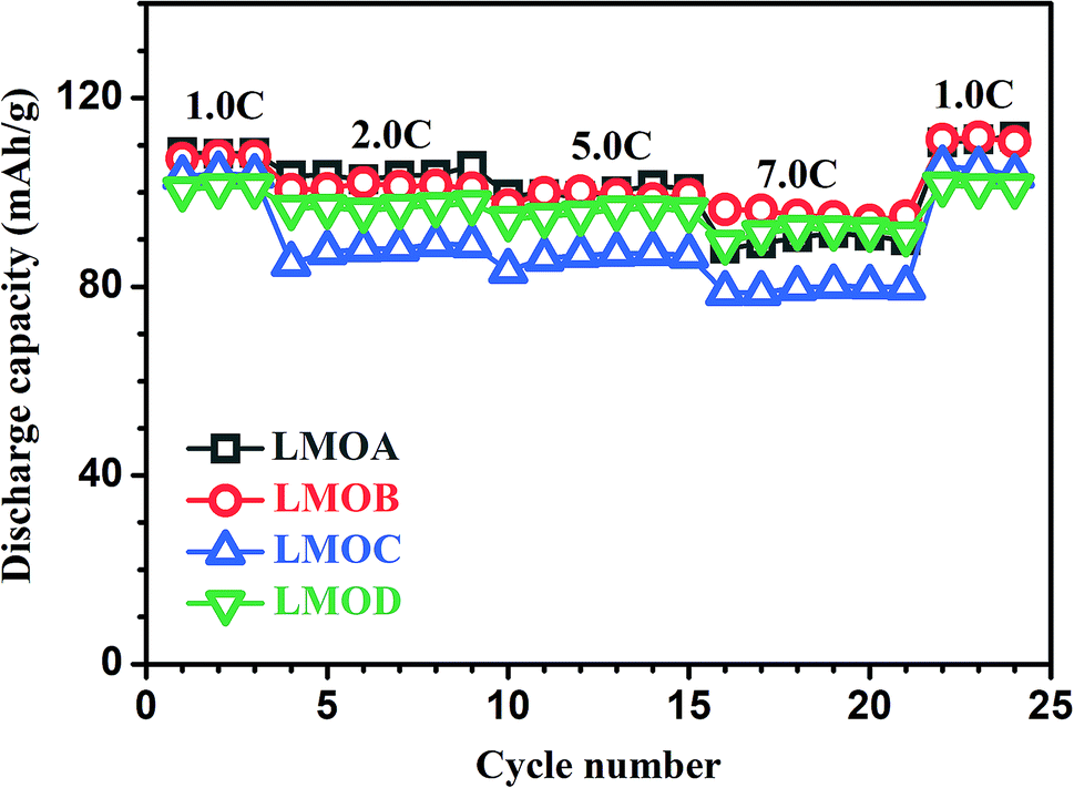
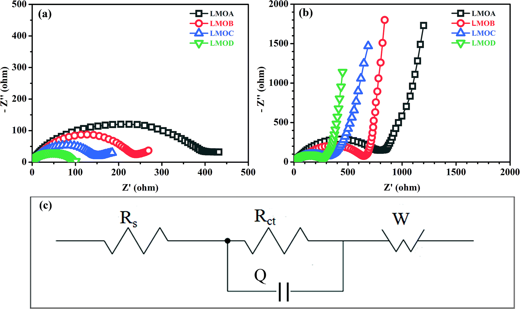
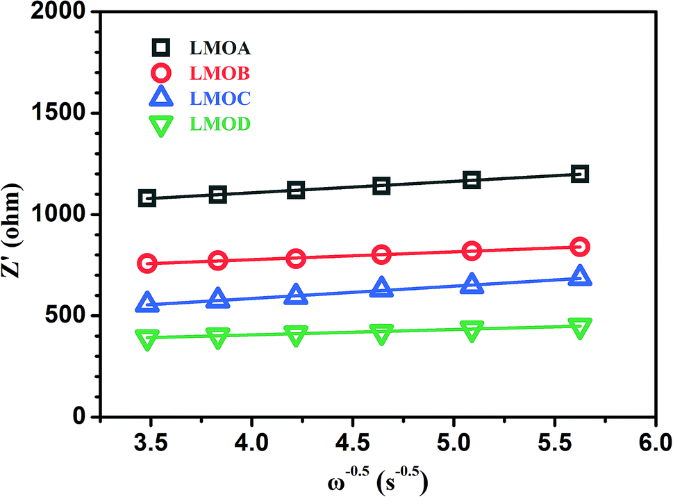
Fig. 6 presents the normalized discharge capacity of all samples cycled at different current rates between 3.0 and 4.2 V (vs. Li/Li+). Overall, their discharge capacities decreased gradually with increasing C-rate at first and then, the capacities increased with decreasing C-rate, reaching a minimum at the highest current density of 7C. Clearly, LMOB and LMOD presented better rate capability than LMOA and LMOC, especially at 7C rate. Fig. 7 shows the EIS graph of Nb-doped LMO with and without coating in the fully discharged state in the (a) 1st and (b) 100th cycle. All the Nyquist plots contain a semicircle in the higher frequency ranges and an inclined straight line in the lower frequency ranges. The diameter of the semicircle represents the charge-transfer resistance (Rct) at the electrode/electrolyte interface, and the inclined straight line corresponds to the diffusion of lithium ions into the bulk of the electrode (Warburg impedance). The spectrum was fitted well on an equivalent circuit shown in Fig. 7c, where Rs, Q, Rct, and Zw represent the ohmic resistance of the electrolyte, constant phase element (CPE), charge-transfer resistance, and Warburg impedance arising from the diffusion of Li+ ions in the electrode, respectively. The values of Rs and Rct are listed in Table 2. Notably, Rs in the case of sample LMOA without coating exhibited the largest increase after 100 cycles among the values of all samples, suggesting that surface coating can effectively inhibit the dissolution of an active material into the electrolyte, due to which the conductivity remains unchanged. The sample LMOD exhibited the smallest charge transfer resistance in both the 1st and 100th cycle among all samples, demonstrating its best electrochemical activity. The diffusion coefficient of lithium ions could be calculated from the plots in the low-frequency region according to the following two equations:14,34
| |
 | (8) |
| | |
Z′ = Rs + Rct + σω−0.5
| (9) |
Here,
R is the gas constant,
T is the absolute temperature,
A is approximately equal to the electrode area (cm
2),
n is the number of electrons in the specific electrochemical reactions,
F is the Faraday constant, and
C is the molar Li
+ ion concentration;
Z′ is the real part of the impedance,
ω is the angular frequency in the low-frequency region, and
σ is the Warburg factor. Based on experimental results in the low-frequency zone, the relationship between
Zre and the reciprocal square root of
ω can be obtained, as depicted in
Fig. 8. The
σ values of samples LMOA, LMOB, LMOC and LMOD could be further concluded as 56.16, 38.55, 60.76 and 26.48, and the diffusion coefficients of lithium ions in these four samples were 1.02 × 10
−14 cm
2 s
−1, 2.16 × 10
−14 cm
2 s
−1, 8.69 × 10
−15 cm
2 s
−1 and 4.58 × 10
−14 cm
2 s
−1, respectively. Clearly, the sample LMOD exhibited the highest Li
+ ion diffusion coefficient, suggesting the beneficial effect of appropriate morphology and coating on increasing the Li
+ ion diffusion coefficient.
 |
| | Fig. 6 The rate performances of LMOA, LMOB, LMOC and LMOD at various current densities. | |
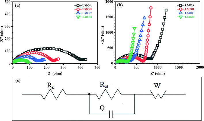 |
| | Fig. 7 Nyquist plots of samples LMOA, LMOB, LMOC and LMOD with an amplitude of 5.0 mV over a frequency range from 100 kHz to 0.01 Hz in the discharged state of 4.0 V: (a) in the first cycle; (b) in the 100th cycle; (c) the equivalent circuit. | |
Table 2 The fitting results of EIS spectra based on the equivalent circuit
| Sample |
1st cycle |
100th cycle |
| Rs/Ω |
Rct/Ω |
Rs/Ω |
Rct/Ω |
| LMOA |
3.83 |
275.30 |
10.19 |
886.60 |
| LMOB |
2.95 |
249.40 |
6.79 |
624.00 |
| LMOC |
4.53 |
148.80 |
2.11 |
341.50 |
| LMOD |
2.41 |
91.90 |
2.52 |
302.50 |
Table 3 Comparison of the cycling performances of LMO between our work and literature
| Sources |
Performance |
| Initial capacity (mA h g−1) and capacity retention after n cycles at RT |
Initial capacity (mA h g−1) and capacity retention after n cycles at 55 °C |
| Our work |
101.7, 96.3% after 300 cycles |
105.11, 98% after 50 cycles |
| LiMn2O4 (ref. 19) |
104.2, 61.9 after 150 cycles |
|
| Al-doped LiMn2O4 (ref. 31) |
Unknown |
93.1, 96 after 30 cycles |
| Mg-doped LiMg0.08Mn1.92O4 (ref. 33) |
99.3, 93.2 after 150 cycles |
Unknown |
| Ce-doped LiMn1.99Ce0.01O4 (ref. 12) |
106, 85% after 150 cycles |
Unknown |
| Nb-doped LiMn1.5Nb0.5O4 (ref. 18) |
115, 87% after 100 cycles |
Unknown |
| Ni, Mn codoped LiNi0.03Mo0.01Mn1.96O4 (ref. 19) |
114, 91.2% after 300 cycles |
Unknown |
| La–Sr–Mn–O coated LiMn2O4 (ref. 35) |
129.9, 90.6% after 500 cycles |
129.9, 93.6% after 130 cycles |
| AlF3-coated LiMn2O4 (ref. 15) |
103.4, 90% after 100 cycles |
Unknown |
| V2O5-coated LiMn2O4 (ref. 17) |
113, 90% after 200 cycles |
112.7, 79.7% after 100 cycles |
| ZrO2-coated LiMn2O4 (ref. 36) |
118, 90.1% after 400 cycles |
119, 88.9% after 150 cycles |
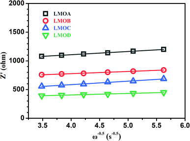 |
| | Fig. 8 The plot comparison of Z′ vs. ω−0.5 of samples LMOA, LMOB, LMOC and LMOD. | |
4. Conclusions
We successfully fabricated Nb-doped LMO with Al2O3 and/or B2O3 coatings and different morphologies by modified solid-state sintering. The morphology of Nb-doped LMO could be controlled via using different Mn oxides as precursors, on which the surface coating could be realized through mixing with Al(OH)3 and/or B2O3 and sintering at 750 °C. During this, the liquid B2O3 layer could suppress LMO particle growth, whereas the Al2O3 layer played a negligible role. Eventually, Nb-doped and Al2O3 + B2O3-coated granular LMO secondary particles, consisting of 350 nm spherical primary particles, were obtained with superior electrochemical performance; we also observed high capacity retention of 96.31% after 300 cycles at RT and that of 98% after 50 cycles at 55 °C at 1C rate.
Conflicts of interest
There are no conflicts to declare.
Acknowledgements
This work was financially supported by the National Natural Science Foundation of China (Grant No. 51502300) and the Anhui Provincial Natural Science Foundation (Grant No. 1608085QE88).
Notes and references
- J. M. Tarascon and M. Armand, Nature, 2001, 414, 359–367 CrossRef CAS PubMed.
- D. Larcher and J. M. Tarascon, Nat. Chem., 2015, 7, 19–29 CrossRef CAS PubMed.
- L. Ben, H. Yu, B. Chen, Y. Chen, Y. Gong, X. Yang, L. Gu and X. Huang, ACS Appl. Mater. Interfaces, 2017, 9, 35463–35475 CrossRef CAS PubMed.
- J. M. Paulsen, C. L. Thomas and J. R. Dahn, J. Electrochem. Soc., 1999, 146, 3560–3565 CrossRef CAS.
- A. V. Potapenko and S. A. Kirillov, Electrochim. Acta, 2017, 258, 9–16 CrossRef CAS.
- J.-S. Kim, K. Kim, W. Cho, W. H. Shin, R. Kanno and J. W. Choi, Nano Lett., 2012, 12, 6358–6365 CrossRef CAS PubMed.
- R. Wang, X. Li, Z. Wang and H. Zhang, Nano Energy, 2017, 34, 131–140 CrossRef CAS.
- X. Chen, G. Xu, X. Ren, Z. Li, X. Qi, K. Huang, H. Zhang, Z. Huang and J. Zhong, J. Mater. Chem. A, 2017, 5, 6581–6588 RSC.
- M. Qiu, Z. T. Sun, D. K. Sang, X. G. Han, H. Zhang and C. M. Niu, Nanoscale, 2017, 9, 13384–13403 RSC.
- D. Deng, Energy Sci. Eng., 2015, 3, 385–418 CrossRef.
- M. Armand and J. M. Tarascon, Nature, 2008, 451, 652 CrossRef CAS PubMed.
- M. Michalska, D. A. Ziółkowska, J. B. Jasiński, P. H. Lee, P. Ławniczak, B. Andrzejewski, A. Ostrowski, W. Bednarski, S. H. Wu and J. Y. Lin, Electrochim. Acta, 2018, 276, 37–46 CrossRef CAS.
- C. Jiang, Z. Tang, S. Wang and Z. Zhang, J. Power Sources, 2017, 357, 144–148 CrossRef CAS.
- S. Tao, H. Zhao, C. Wu, H. Xie, P. Cui, T. Xiang, S. Chen, L. Zhang, Y. Fang, Z. Wang, W. Chu, B. Qian and L. Song, Mater. Chem. Phys., 2017, 199, 203–208 CrossRef CAS.
- A. Tron, Y. D. Park and J. Mun, J. Power Sources, 2016, 325, 360–364 CrossRef CAS.
- G. H. Waller, P. D. Brooke, B. H. Rainwater, S. Y. Lai, R. Hu, Y. Ding, F. M. Alamgir, K. H. Sandhage and M. L. Liu, J. Power Sources, 2016, 306, 162–170 CrossRef CAS.
- H. Ming, Y. Yan, J. Ming, J. Adkins, X. Li, Q. Zhou and J. Zheng, Electrochim. Acta, 2014, 120, 390–397 CrossRef CAS.
- T.-F. Yi, Y. Xie, Y.-R. Zhu, R.-S. Zhu and M.-F. Ye, J. Power Sources, 2012, 211, 59–65 CrossRef CAS.
- M. Chen, P. Chen, F. Yang, H. Song and S. Liao, Electrochim. Acta, 2016, 206, 356–365 CrossRef CAS.
- Y. Fu, H. Jiang, Y. Hu, Y. Dai, L. Zhang and C. Li, Ind. Eng. Chem. Res., 2015, 54, 3800–3805 CrossRef CAS.
- L. Xiao, Y. Guo, D. Qu, B. Deng, H. Liu and D. Tang, J. Power Sources, 2013, 225, 286–292 CrossRef CAS.
- H.-L. Zhu, Z.-Y. Chen, S. Ji and V. Linkov, Solid State Ionics, 2008, 179, 1788–1793 CrossRef CAS.
- M. M. Thackeray, Prog. Solid State Chem., 1997, 25, 1–71 CrossRef CAS.
- B. Zhu, B. Fang and X. Li, Ceram. Int., 2010, 36, 2493–2498 CrossRef CAS.
- X. Hu, L. Cui, T. Liu, Z. Zheng, Y. Tang and A. Lu, J. Non-Cryst. Solids, 2015, 427, 69–75 CrossRef CAS.
- G. Xia, N. Li, D. Li, R. Liu, N. Xiao and D. Tian, Mater. Lett., 2012, 79, 58–60 CrossRef CAS.
- M. He, X. L. Chen, B. Q. Hu, T. Zhou, Y. P. Xu and T. Xu, J. Solid State Chem., 2002, 165, 187–192 CrossRef CAS.
- F. Marchini, E. J. Calvo and F. J. Williams, Electrochim. Acta, 2018, 269, 706–713 CrossRef CAS.
- Y. Fu, Y.-J. Gu, Y.-B. Chen, H.-Q. Liu and H.-H. Zhou, Solid State Ionics, 2018, 320, 16–23 CrossRef CAS.
- M.-Y. Zhao, Z.-Y. Ji, Y.-G. Zhang, Z.-Y. Guo, Y.-Y. Zhao, J. Liu and J.-S. Yuan, Electrochim. Acta, 2017, 252, 350–361 CrossRef CAS.
- T. Kakuda, K. Uematsu, K. Toda and M. Sato, J. Power Sources, 2007, 167, 499–503 CrossRef CAS.
- T. Eriksson, A. M. Andersson, C. Gejke, T. Gustafsson and J. O. Thomas, Langmuir, 2002, 18, 3609–3619 CrossRef CAS.
- M. Xiang, C.-W. Su, L. Feng, M. Yuan and J. Guo, Electrochim. Acta, 2014, 125, 524–529 CrossRef CAS.
- C. Yang, S. Yu, C. Lin, F. Lv, S. Wu, Y. Yang, W. Wang, Z.-Z. Zhu, J. Li, N. Wang and S. Guo, ACS Nano, 2017, 11, 4217–4224 CrossRef CAS PubMed.
- H.-Q. Wang, F.-Y. Lai, Y. Li, X.-H. Zhang, Y.-G. Huang, S.-J. Hu and Q.-Y. Li, Electrochim. Acta, 2015, 177, 290–297 CrossRef CAS.
- G. Li, X. Chen, Y. Liu, Y. Chen and W. Yang, RSC Adv., 2018, 8, 16753–16761 RSC.
Footnote |
| † These authors contributed equally to this work. |
|
| This journal is © The Royal Society of Chemistry 2019 |
Click here to see how this site uses Cookies. View our privacy policy here. 
 Open Access Article
 This Open Access Article is licensed under a Creative Commons Attribution-Non Commercial 3.0 Unported Licence
 *a,
Zhuoming Xiea,
Tao Zhanga,
Jianxin Wangc,
Qianfeng Fangab and
Xianping Wang*a
*a,
Zhuoming Xiea,
Tao Zhanga,
Jianxin Wangc,
Qianfeng Fangab and
Xianping Wang*a