 Open Access Article
Orientation effects on the nanoscale adsorption behavior of bone morphogenetic protein-2 on hydrophilic silicon dioxide†
Izabele Marquetti a and
Salil Desai
 *ab
*ab
aDepartment of Industrial & Systems Engineering, North Carolina A&T State University, Greensboro, NC 27411, USA. E-mail: sdesai@ncat.edu
bWake Forest Institute for Regenerative Medicine, Wake Forest School of Medicine, Winston–Salem, NC 27157, USA
First published on 8th January 2019
Abstract
Bone Morphogenetic Protein-2 (BMP-2) is a growth factor associated with different developmental functions in regenerative medicine and tissue engineering. Because of its favorable properties for the development of bone and cartilage tissue, BMP-2 promotes the biocompatibility of medical implants. In this research, molecular dynamics simulations were implemented to simulate the interaction of BMP-2 with a flat hydrophilic silicon dioxide substrate, an important biomaterial for medical applications. We considered the influence of four orthogonal protein orientations on the adsorption behavior. Results showed that arginine and lysine were the main residues to interact with the silicon dioxide substrate, directly adsorbing onto the surface and overcoming water layers. However, between these charged residues, we observed a preference for arginine to adsorb. Orientations with the α-helix loop closer to the surface at the beginning of the simulations had greater loss of secondary structure as compared to the other configurations. Among all the orientations, the end-on B configuration had favorable adsorption characteristics with a binding energy of 14![[thin space (1/6-em)]](https://www.rsc.org/images/entities/char_2009.gif) 000 kJ mol−1 and retention of 21.7% β-sheets as confirmed by the Ramachandran plots. This research provides new insights into the nanoscale interaction of BMP-2 and silicon dioxide substrate with applications in orthopedic implants and regenerative medicine.
000 kJ mol−1 and retention of 21.7% β-sheets as confirmed by the Ramachandran plots. This research provides new insights into the nanoscale interaction of BMP-2 and silicon dioxide substrate with applications in orthopedic implants and regenerative medicine.
1 Introduction
Distinct signals such as soluble signaling molecules, insoluble ligands, mechanical cues, and cell interactions control tissue development. Proteins are usually associated with these processes because of their biological activity, making them probable therapeutics. Growth factors and immobilized ligands are responsible for controlling cell adhesion, migration, proliferation, and differentiation. Because tissue regeneration is influenced by transplanted or host cells according to local environmental signals, growth factors are extremely important in regenerative medicine.1 Cells secrete bone growth factors to drive osteoblast functions by interacting with membrane receptors on the target tissue, and thus, inducing intracellular signals that cause a biological response.2,3Bone morphogenetic proteins (BMPs) are growth factors belonging to the transforming growth factor-β family essential for the formation and regeneration of bone tissue. Bone morphogenetic protein-2 has proven to be effective at inducing bone formation due to its ability to promote differentiation and proliferation of osteoblasts.4,5 BMP-2 signals through their binding to BMP type I and type II receptors, which are cell transmembrane serine/threonine kinase receptors.6 The wrist and knuckle epitopes are the primary domains for binding of BMPs and their receptors. The wrist epitope has high affinity to bind with BMPR-IA and BMPR-IB and knuckle with BMPR-II.7
Implantable biomaterials with the capacity to deliver BMP-2 are a promising approach for effective bone regeneration.8–11 The enhancement of the surface properties of a biomaterial is critical to improving the interaction between cells and implants, allowing a significant decrease in the healing time.11,12 Surface modification enhances the biological functionalities of implants while maintaining their mechanical properties.11,13
An adequate delivery system for BMPs needs to retain them at the local injury for an extended time frame, serving as support where the cells can be attached and develop the tissue to be regenerated.14 The biomaterial should secure BMPs against degradation while conserving its bioactivity and efficiently releasing the growth factor to guarantee the regeneration of the bone. Some methodologies can be used for the retention of BMP in a delivery system, including surface adsorption, ionic complexation, covalent binding, chemical conjugation, and immobilization or physical entrapment.14 Protein adsorption occurs when the monomer is attracted by the surface of a material.15 However, conformational changes usually occur because the monomer tends to spread out extensively on the surface, limiting the release of the BMP.14,16 Protein adsorption directly depends on environmental conditions including pH, temperature, ionic strength, substrate porosity, and protein-substrate interaction.14
For the formation of bone tissue, BMP-2 must be available in a relatively high local concentration and remain exclusive on the region to be treated. Excessive concentrations of the protein can cause side effects outside the implant site, including inflammatory responses, ectopic bone formation, wound complications, and osteolysis activation.9 Also, BMP-2 loses its bioactivity in solution after a short time in vivo, and paired with high costs, makes high dose clinical treatments unfeasible.12
Different materials have been used to incorporate BMP-2 for bone regeneration therapies, including inorganic materials,17,18 natural19 or synthetic polymers,2,20 and composites.21 However, for the successful implementation of bone defect therapy, issues related to immobilization of BMP-2 onto biomaterials and limited in vivo efficacy need to be addressed.8 Silicon dioxide (SiO2) is a commonly used inorganic material for studying proteins due to its biocompatibility and biodegradability with medical applications in drug delivery and bone repair.22 Recent application of silicon dioxide involves its use combined with hydroxyapatite as a binding layer for metallic implants to avoid bacterial attachment.23 Silica-based mesoporous nanomaterials emerged as a carrier to deliver therapeutic and diagnostic agents in different types of cells due to its low toxicity and high versatility when compared to other inorganic nanomaterials or conventional nanocarriers.24
Understanding the interaction of the BMP-2 protein with silica is essential to maximizing the performance of engineered bone tissues. A detailed comprehension of the protein adsorption allows optimizing materials for biotechnological applications with better biocompatibility and performance. Molecular dynamics (MD) simulations provide a computational perspective to understand the nanoscale protein-substrate interaction which may be difficult to analyze experimentally.8 Also, MD models assist in the visualization of conformational changes and the bioactivity of a protein.8,25 MD simulations have been used to study the interaction of BMP-2 molecules with different substrates of medical relevance including graphite,26–28 gold,29 hydroxyapatite,8,30 titanium dioxide,28 and silicon nitride.29 However, to the best of our knowledge, no studies have analyzed the nanoscale interaction of BMP-2 with silicon dioxide.
In this research, our group investigates the nanoscale interaction of a BMP-2 molecule with a hydrophilic silicon dioxide substrate using MD simulations. The effects of four initial orthogonal orientations of BMP-2 on the nanoscale adsorption behavior were evaluated.
2 Computational methods
MD simulations were performed with NAMD31 source code version 2.11 using CHARMM force field on a 64 bit Linux platform (Fedora 21). Graphical processing units (GPUs) from NVIDIA® Corporation (K40 and K20, with 2880 and 2496 cores, respectively) were employed to execute the simulations. Also, simulations were run on GPU computing resources provided by XSEDE (K80, with 4992 cores).32 GPUs have been used to accelerate scientific computations, including complex computational problems for biological systems and high-performance MD simulations.33–35Initial crystallographic structure for BMP-2 (ID: 3BMP) was retrieved from the RCSB Protein Data Bank.36 This protein consists of 114 residues, however the residues 1 to 8 (belonging to the N-terminus) are not represented because they are too flexible to be detected.37 BMP-2 molecule contains one α-helix with four-turn helix, and two double-stranded anti-parallel β-sheets structures. The net charge of the BMP-2 is −2e. Lys (lysine) and Arg (arginine) residues were taken to be protonated, while Glu (glutamic acid) and Asp (aspartic acid) deprotonated. All His (histidine) residues adopted the protonated state HSE. The native-state protein was solvated in water using an explicit TIP3P water model38 Na+ and Cl− ions were added at a concentration of 0.15 mol L−1 using Visual Molecular Dynamics (VMD)39 resulting in a final protein model with 13![[thin space (1/6-em)]](https://www.rsc.org/images/entities/char_2009.gif) 863 atoms. The total system charge was 1.140 × 10⁻⁶ (i.e. neutral).
863 atoms. The total system charge was 1.140 × 10⁻⁶ (i.e. neutral).
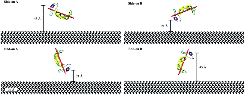
For this study, we considered four initial orientations (two side-on and two end-on) on hydrophilic silica which were obtained by rotating the protein through 90° (Fig. 1). Fig. 1 represents the quantitative characterization40,41 of the orientation angles and protein proximity concerning the substrate. The end-on A and side-on B configurations had the α-helix at 21 Å from the substrate. Whereas, the side-on A and end-on B configurations had the α-helix at 43 Å and 45 Å from the substrate, respectively. The dipole moments for end-on A and end-on B configurations were aligned at 70° with respect to the substrate but in opposing directions (towards and away from the substrate). Whereas, the dipole moments for the side-on configurations were aligned at 20° with the substrate.
The solvated protein was positioned on the center of the flat SiO2 surface (100), with dimensions (203 × 203 × 20 Å), that was large enough to allow the movement of the protein. The lattice plane (100) was chosen as it has shown high affinity for adsorption with proteins and self-assembled monolayers in several studies.42,43 In addition, this plane enhances the formation of (Si–OH) bonds resulting in a hydrophilic substrate behavior which promotes adsorption sites for the BMP-2 molecule. The SiO2 substrate was created using VMD plugin inorganic builder (unit cell parameters a = b = 4.978 Å and c = 6.948). The total simulation box was 203 × 203 × 87 Å. The average distance between the protein and the substrate was 16 Å.
MD simulations use total potential energy that accounts for bonded (stretching, bending, torsional) and non-bonded interactions (van der Waals and electrostatic). van der Waals interactions are intermolecular, where there is a weak attractive or repulsive force between molecules caused by non-covalent interactions (eqn (2)). The electrostatic interaction is due to the different distribution of charge in a molecule, and it is described by a Coulomb potential (eqn (1)).44
 | (1) |
 | (2) |
The bonded and non-bonded parameters for the water and BMP-2 molecules were obtained from the CHARMM force fields.45 The non-bonded force field parameters for silicon dioxide include, σij(Si) = 4.295 Å, εij(Si) = −1.255 kJ mol−1, σij(O) = 3.500 Å, and εij(O) = −0.628 kJ mol−1.46 These parameters replicate the experimental water contact angle of 23° for silicon dioxide surface.47,48
The systems were minimized for 0.2 ns and simulated for 20 ns with a 2 fs time step for the integration of Newton equations. A cutoff distance of 12 Å was used for the van der Waals interactions. Periodic boundary conditions were applied in x and y directions to prevent the edge effects of the simulation box on the adsorption behavior of the protein. Thus, in the x and y directions the minimum image convention was applied. In the z direction, a hard wall constraint was placed on the top and bottom of the simulation box. A constant temperature of 310 K was maintained using the Langevin temperature control. All the atoms in the substrates were kept fixed to aid computational efficiency. The results were analyzed with VMD and MATLAB R2017a post-processing tools.
The root-mean-square deviation (RMSD) was calculated to obtain the average position of the atoms during the 20 ns simulations (eqn (3)). RMSD is also a measure of the equilibration of the system wherein; a steady-state value indicates no more variations of the potential energy.39
 | (3) |
The adsorption process was evaluated based on the adsorption energy and the number of contacts made by residues. Adsorption energy corresponds to the non-bonded interaction energy between the protein and the substrate,28 composed by the van der Waals and electrostatic energies. The number of contacts is the number of atoms in a residue that are within 5 Å distance of the substrate surface. The secondary structure of the initial configuration was compared to the final conformation to evaluate protein denaturation by using VMD plugin Timeline. Denaturation occurs when the α-helix and β-sheet structures are disrupted and transformed to a random coil state.49 Also, Ramachandran plots were used to validate the secondary structure of the protein by analyzing the changes in the ψ and φ torsion angles of the residues.
The radius of gyration (Rg) was calculated by eqn (4) to measure the compaction level of the protein, which characterizes the protein conformation. A significant fold or unfold of the protein leads to denaturation and loss of bioavailability.
 | (4) |
3 Results and discussion
The root-mean-square-deviation (RMSD) of the atomic coordinates are shown in Fig. 2a and presents the structural stability of the protein backbone over time. Equilibration state was reached at approximately 1 ns for end-on A and side-on A orientations, and at 2 ns for end-on B and side-on B orientations. Therefore, the total time scale of 20 ns was adequate to study the adsorption behavior on this substrate.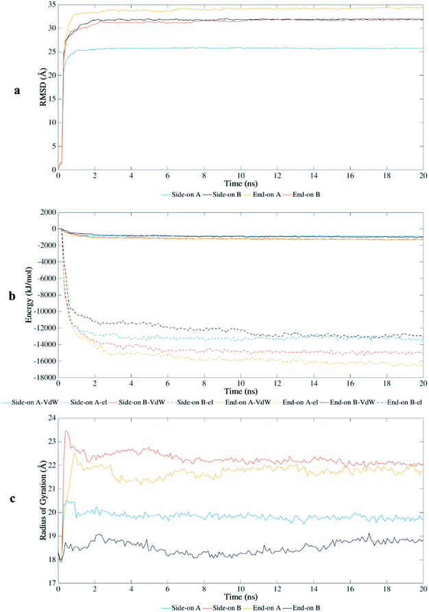 | ||
| Fig. 2 Interaction of BMP-2 with hydrophilic silica during MD simulations: (a) root-mean-square-deviation, (b) van der Waals (VdW) and electrostatic (el) energy, and (c) radius of gyration. | ||
BMP-2 moves rapidly towards the silica substrate, within 0.5 ns, independent of the initial orientation. Fig. 2b shows the influence of the initial orientation of the protein on the adsorption pathway for silica. Although all orientations had similar adsorption profile, the intensity of interaction changes after 1 ns. The electrostatic interactions corresponded to most of the adsorption energy with this substrate, wherein the initial adsorption started after 0.5 ns for all simulations. Fig. 2b shows that the van der Waals interactions are much weaker and the primary contribution to the adsorption occurred due to electrostatic interaction energies between the protein and the substrate. However, the stronger interaction of the protein with silica occurred after 2 ns, reaching higher values of adsorption energy for orientations side-on B and end-on A (−16![[thin space (1/6-em)]](https://www.rsc.org/images/entities/char_2009.gif) 000 and −18
000 and −18![[thin space (1/6-em)]](https://www.rsc.org/images/entities/char_2009.gif) 000 kJ mol−1, respectively). These results show that adsorption energies on silicon dioxide are approximately ten times greater than those obtained in a previous study with the same conditions using hydrophilic silicon nitride as substrate.29
000 kJ mol−1, respectively). These results show that adsorption energies on silicon dioxide are approximately ten times greater than those obtained in a previous study with the same conditions using hydrophilic silicon nitride as substrate.29
The radius of gyration (Rg) shows the unfolding behavior of the protein structure for the simulations performed with silica (Fig. 2c). The orientations side-on B and end-on A presented a more unfolded conformation with average Rg of 22.2 Å and 21.7 Å, respectively. The unfolded conformation for these initial orientations contributed to the stronger adsorption on the substrate because more residues were available to interact with the surface. End-on B had the most compacted conformation (average Rg of 18.53 Å) with lower values of adsorption energy, followed by side-on A (average Rg of 19.82 Å).
The end-on B and side-on A had lower values of radius of gyration representing a less unfolded structure, preserving parts of their secondary structure as compared to the other orientations. These orientations presented weaker interaction energies which limited the denaturation of the protein structure. End-on A orientation had the strongest binding with the substrate, but most of the secondary structure was disrupted (Table 1). This orientation spread out at the early stages of the simulation, forming a flat monolayer after 1 ns and disrupting most β-sheets after 2 ns.
| Secondary structure | Initial structure | Side-on A | Side-on B | End-on A | End-on B |
|---|---|---|---|---|---|
| α-helix | 10.38% | 5.66% | 0.00% | 3.77% | 0.00% |
| 310-helix | 0.00% | 2.83% | 0.00% | 2.83% | 0.00% |
| β-sheet | 44.34% | 7.55% | 4.72% | 0.00% | 21.70% |
Table 1 presents a comparison of the secondary structure of the protein at the beginning and after 20 ns simulations for all initial orientations. Orientations with the α-helix loop closer to the surface at the beginning of the simulations (side-on B and end-on A) had greater loss of secondary structure. Side-on B orientation, the spreading of water molecules caused stretching of the protein on the longitudinal axis at the beginning of the simulation (0.3 ns), destroying almost completely its secondary structure with only 4.72% of β-sheets being preserved. A different behavior occurred for the end-on A orientation where the protein unfolded on the lateral axis after 1 ns. The steady unfolded conformation of the protein allowed more residues to contact the surface causing strong adsorption after 2 ns. The strong binding of the protein to silica completely disrupted the β-sheets structure, and a great reduction of the α-helix occurred (from 10.38% to 3.77%). End-on B orientation had the lower reduction in the β-sheets structures (from 44.34% to 21.70%) as compared to the other configurations for silica. However, throughout the simulation, there was a constant disruption followed by the formation of β-sheets, especially after 7 ns. Also, all α-helix structures were destroyed after 12 ns. The side-on A orientation had the most content of α-helix structures 5.66% preserved, while part of it was transformed to 310-helix (2.83% of the total structure).
In a peptide chain, the N–Cα and Cα–C bonds (carbonyl oxygen and amide hydrogen in transposition) are relatively free to rotate. The angle of rotation, known as torsion or dihedral angle, determines the 3D format of the polypeptide backbone, in which phi (φ) is the angle around N–Cα bond and psi (ψ) around the Cα–C bond.50 The Ramachandran plot (Fig. 3) represents the distribution of the φ and ψ torsion angles in the protein at the beginning and the end of the simulations for end-on A and B configurations. The Ramachandran plot is shown for all the residues in the protein along with specific residues in the wrist and knuckle epitopes. Fig. 3 presents the structural validation of the BMP-2, the blue color represents the most favorable regions for α-helix and β-sheet, while the green color represents the less favorable regions, and the white color the disallowed regions. Residues falling within the white region show a loss of the secondary structure. The end-on B configuration shows that high amounts of amino acids with permitted backbone conformations for psi/phi angle pairs as compared to end-on A orientation. This confirms the significant loss of secondary structure for end-on A orientation as presented in Table 1 wherein the protein formed a monolayer on the substrate. Specifically, residues from the allowable β-sheet regions are seen to be spread out to other regions on the plot. On the other hand, end-on B configuration has residues from the α-helix regions spread out to non-allowable regions of the plot confirming the formation of random coil structures as can be seen in Fig. 4.
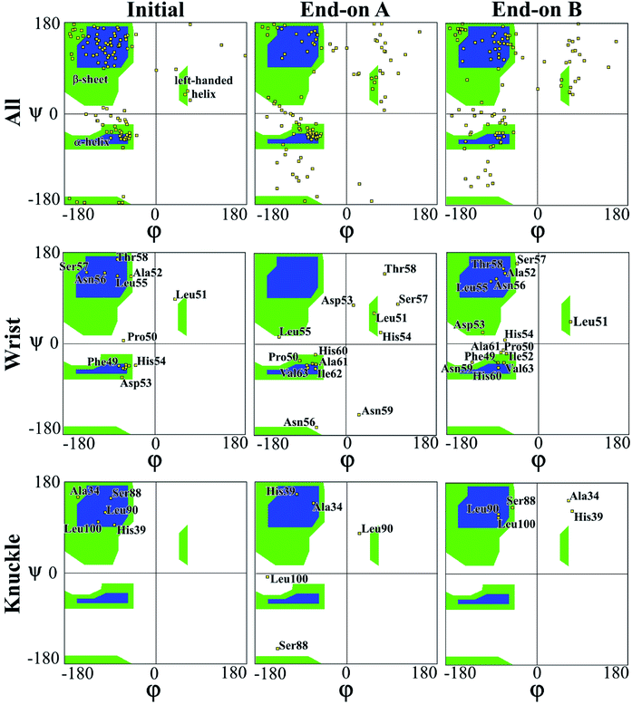 | ||
| Fig. 3 Ramachandran plot for evaluating 3D protein structure of end-on A and end-on B configurations. | ||
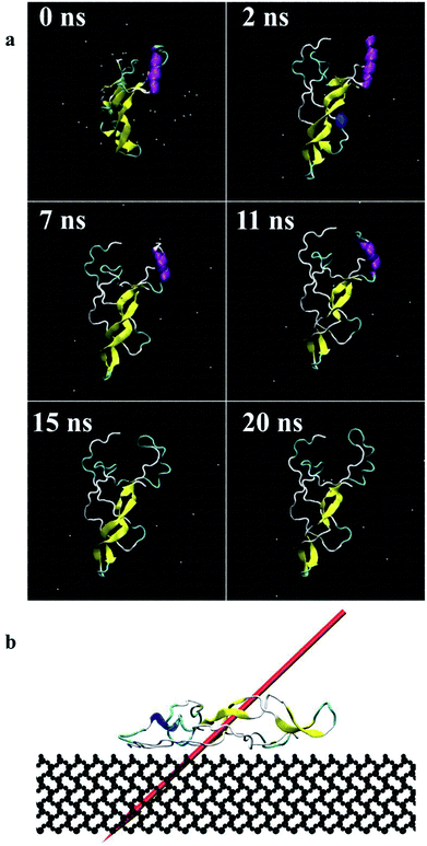 | ||
| Fig. 4 Screenshots of the protein (end-on B) (a) during 20 ns simulations, top view, (b) dipole moment in final adsorbed state after 20 ns, side view (dipole moments for other orientations are shown as ESI†). | ||
The Ramachandran plots for wrist epitopes for both orientations show prominent residues that permit binding to type I and II receptors to initiate the SMAD pathway. Fig. 3 clearly shows that the end-on A orientation had most of its residues out of the permissible regions for the wrist epitope indicating denaturing of the protein due to steric hindrance. These include loss of backbone structure for the anti-parallel β-sheet residues (Ala52, Leu55, Asn56, Ser57, Thr58) and α-helix residues (His54, Asp53, and Asn56), respectively. Similarly, the knuckle epitope residues (Ser88, Leu90, and Leu100) were displaced from the permissible regions for the end-on A orientation with the breaking of the stable hydrogen bonds. In contrast, a significant number of residues belonging to the wrist epitopes (Thr58, Leu55, Ala52, Phe49, Asn56) and knuckle epitopes in the end-on B orientation maintained their secondary structures providing binding sites for type I and II receptors. Thus, the Ramachandran plot delineates favorable residues for both wrist and knuckle epitopes in the end-on B configuration to promote successful adsorption and bioactivity.
Fig. 4 presents the top view time evolution of the secondary structure for the end-on B orientation over the 20 ns simulation period. During the initial 0.2 ns to 0.5 ns, the BMP-2 molecule rapidly descends to the substrate with the β-sheets folding onto the hydrophobic core. The Arg9 residue forms an anchor point on the substrate pivoting the protein to rock about itself, which is followed by an immediate binding of Arg16 residue and subsequent Arg114 residue. The α-helix is retained until 11 ns and disintegrates into a random coil structure after that. Beyond 12 ns there is an alternate gain and loss of β-sheets preserving a partial structure of the knuckle epitope. The Leu51 and Asp 53 residues in the wrist epitope provide binding sites to BMP-2 and were available at 14 Å and 19 Å, respectively from the substrate surface for receptor IA. Similarly, the knuckle epitope had polar residue Ser88 (10 Å) and hydrophobic residue Leu100 (8 Å) from the substrate for type II receptor binding. Moreover, these residues have retained their backbone structure as per the Ramachandran plots for side-on B orientation maintaining their bioactivity. Thus, the final adsorbed configuration provided accessibility of “wrist” and “knuckle” epitopes for ligand–receptor interactions. The long side chain residues Lysine (Lys 11, 15, 73, 76) were able to align their chain parallel to the silica thereby, maximizing their interaction and forming a stable bond with the substrate. Similarly, the Arg residues (9, 16, 114) formed anchor points to adsorb with the substrate. Thus, the rapid rise in the binding interaction energy for side-on B orientation (−12![[thin space (1/6-em)]](https://www.rsc.org/images/entities/char_2009.gif) 000 kJ mol−1) in the first 2 ns of the adsorption phase is primarily contributed by the charged residues.
000 kJ mol−1) in the first 2 ns of the adsorption phase is primarily contributed by the charged residues.
In the final configuration, the dipole moment for the end-on B orientation was at 45° with respect to the substrate pointing towards the surface as shown in Fig. 4b. The other final orientations had similar dipole moments. The final orientation dipole moments are dictated by the stability of the secondary structure and placement of the α-helix and β-sheet components of the BMP-2 molecule. In the case of end-on B orientation, the β-sheet had initial contact with the substrate followed by the α-helix touch-down. The retention of the partial β-sheet structure beyond 12 ns resulted in side-chain residues to align parallel to the silica. The anchoring of the Arg residues provided further binding with the substrate. The final orientation of the end-on B configuration is a resultant of the binding mechanism of prominent residues of the α-helix and β-sheet components.
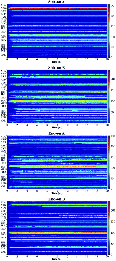
Fig. 5 shows the plot of the number of contacts, which represents the number of atoms in a residue that are within 5 Å distance (adsorbing area) of the substrate surface.51 This plot presents the number of atoms in each residue that are adsorbing onto the surface and allows to quantify the number of contact points between protein and surface.52 Red regions represent stronger interaction of the residues with the substrate, whereas blue regions indicate that no contact occurs with the substrate within 5 Å. The yellow regions represent intermediate interaction of the residues with the substrate.
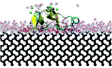
In this research, all the orientations had a consistent adsorption behavior of the protein. Protein adsorption occurred mainly via water layers, but a direct interaction between the residues and the surface also occurred. The hydrogen atoms in the water molecules arrange towards the negatively charged oxygen atoms of the silica surface, forming a water layer within 2 Å, which prevents some residues in the protein to directly interact with the atoms in the surface (Fig. 6). Only charged residues Arg and Lys, and polar residues Tyr and Ser were able to penetrate the water layer and closely contact the substrate (within 2 Å). The water layer covering the surface explains the lower number of contacts, less than 100 atoms, of most residues adsorbing (Fig. 5), and the minimal distance of more than 2 Å of the adsorbed residues. Similar behavior was observed by Utesch et al.28 who analyzed the adsorption of BMP-2 on TiO2, a hydrophilic substrate. The spreading of the water molecules on the hydrophilic material causes the interaction of polar and charged residues with the surface. This adsorption behavior is followed by the interaction of hydrophobic residues (mainly Leu, Pro, and Val) with the substrate. However, only charged residues Lys and Arg strongly adsorb on the substrate, with more than 150 atoms within 5 Å of the substrate surface (Fig. 5), for all orientations. The polar and hydrophobic residues contribute to less than 80 atoms of contact with the substrate. This is because the hydrophilic silica has a high affinity with sodium ions and positively charged residues Lys and Arg. Meanwhile, the chlorine ions interact with some residues, pulling them upwards away from the surface, which contributes to the disruption of the secondary structure. Thus, the electrostatic interactions attract the protein to the surface at the beginning of the simulations, independent of the initial orientation. Even residues initially located at the upper part of the protein, at distances more than 30 Å from the surface, are strongly adsorbed.
For all orientations, residue Arg9 was the main adsorbed amino acid, with more than 200 atoms within the 5 Å substrate threshold, followed by Lys15 with more than 150 atoms. It is expected that both residues Lys and Arg, which are positively charged residues at pH 7, have the same potential for electrostatic interactions.53 However, we observed a preference for Arg to strongly adsorb on the silica substrate, with more number of atoms contacting the substrate within 5 Å. Similar behavior was observed by Kubiak and Mulheran54 who performed MD simulations of the adsorption behavior of hen egg white lysozyme on silica, and concluded that Arg residues are more important than Lys on the adsorption at the conditions performed. In another study, Hoefling et al.55 observed that Arg residues can penetrate the water layers, facilitating the initial contact with a gold substrate, and therefore, directly adsorbing onto the material. Table 2 presents the average distance between Arg and Lys residues at the beginning and after 20 ns. As we can see from the table, even residues that were positioned at farther distances from the substrate at the beginning of the simulation were able to adsorb. These residues have direct contact with the surface, without water layers. The wrist epitope comprises residues of the pre-helix loop and α-helix (Phe49, Pro50, Leu51, Ala52, Asp53, His54, Leu55, Asn56, Ser57, Thr58, Asn59, His60, Ala91, Ile62, and Val63). The knuckle epitope includes the residues Ala34, His39, Ser88, and Leu100. For the achievement of proper osteogenic bioactivity of the BMP-2, the residues of the wrist and knuckle epitope must be available for ligand–receptor interactions.
| Residue | Side-on A | Side-on B | End-on A | End-on B | ||||
|---|---|---|---|---|---|---|---|---|
| Initial | Final | Initial | Final | Initial | Final | Initial | Final | |
| Arg9 | 32.433 | 2.490 | 32.717 | 2.264 | 40.421 | 2.245 | 27.729 | 2.406 |
| Lys11 | 26.603 | 3.939 | 38.547 | 3.080 | 34.158 | 2.581 | 33.992 | 2.185 |
| Ly15 | 24.857 | 2.561 | 40.293 | 2.626 | 28.807 | 2.862 | 39.342 | 3.024 |
| Arg16 | 23.456 | 2.922 | 42.078 | 5.828 | 30.546 | 2.556 | 37.604 | 2.556 |
| Lys73 | 49.246 | 2.938 | 15.904 | 2.847 | 30.275 | 2.940 | 37.875 | 2.960 |
| Lys76 | 39.032 | 6.801 | 26.118 | 2.369 | 27.697 | 2.834 | 39.328 | 5.824 |
| Lys97 | 32.434 | 5.110 | 32.716 | 3.771 | 49.401 | 3.798 | 18.749 | 5.007 |
| Ly101 | 30.994 | 2.975 | 34.156 | 2.637 | 39.723 | 2.902 | 28.426 | 13.716 |
| Arg114 | 37.644 | 3.605 | 27.506 | 4.551 | 25.184 | 3.525 | 42.966 | 4.398 |
For the end-on B orientation, which had the most β-sheet structure remaining, the residues of the wrist epitope are arranged on the top part of the protein at the end of the simulation, with an average distance of 11.3 Å to the surface. All the α-helix structure was disrupted after 11 ns, and therefore, interactions with BMPR-IA/IB are unlikely to occur. Residues Leu90 and Leu100 preserved their β-sheet structure throughout the simulation, unlike the other residues of the knuckle that had their structure disrupted. In side-on A orientation, most of the residues of the knuckle epitope lost their β-sheet structure at the beginning of the simulations, except His39 which had its structure preserved. Some residues of the wrist epitope also lost their initial structure, including Phe49, Pro50, Leu51, and His60. However, most of them preserved their structure possibly allowing interactions with BMPR-IA/IB receptors. For the other configurations, side-on B and end-on A, we conclude that no significant secondary structure was retained to bind with BMPR-IA/IB and BMPR-II receptors.
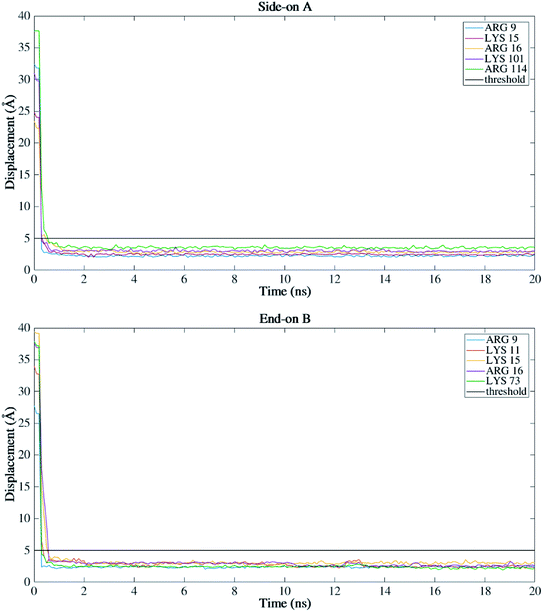
Fig. 7 shows the dominant residues that lie within the 5 Å threshold of the silicon dioxide surface for side-on A and end-on B orientations. These configurations had higher secondary structure retentions among all the four orthogonal orientations. As can be seen from Fig. 7, both the orientations have Arg and Lys residues within the proximity of the substrate indicating a stable adsorption behavior. These charged residues play a key role in the adsorption with a higher number of contacts >200 (Fig. 5) for both the configurations and almost equivalent binding energy around 14![[thin space (1/6-em)]](https://www.rsc.org/images/entities/char_2009.gif) 000 kJ mol−1 (Fig. 2b). It is important to note that BMP-2 needs to retain both its bioactivity (secondary structure) and adsorption with the substrate to promote osteogenic differentiation. The end-on B orientation was the most suitable candidate among all the four orientations to fulfill this criterion.
000 kJ mol−1 (Fig. 2b). It is important to note that BMP-2 needs to retain both its bioactivity (secondary structure) and adsorption with the substrate to promote osteogenic differentiation. The end-on B orientation was the most suitable candidate among all the four orientations to fulfill this criterion.
The wrist epitopes (Thr58, Leu55, Ala52, Phe49, Asn56) and knuckle epitopes (Ser88, Leu100) in the end-on B orientation maintained their secondary structures, providing binding sites for type I and II receptors. In addition, the Leu51 and Asp53 wrist epitope formed hotspots for binding with receptor IA.28 The retention of the knuckle epitope in this configuration permits binding site for type II serine/threonine receptor kinase involving β7 and β8 strands, respectively. These prominent residues initiate BMP-2 signalling through both canonical and noncanonical pathways. The signal transduction occurs through complex heterotetrameric formation to trigger receptor-regulated Smads (R-Smads) which include Smad1, Smad2, and Smad8 proteins.56 Further, phosphorylating with Co-Smad proteins Smad4 enables regulation of gene expression and cellular activity of osteoblasts. Also, BMP-2 molecule can also initiate noncanonical pathways via the MAPK cascades.57 Thus, the final adsorbed end-on B configuration provided accessibility of “wrist” and “knuckle” epitopes for ligand–receptor interactions. Thereby, retaining its partial bioavailability in the adsorbed state to permit the signalling cascade for osteoblast differentiation and restoration of bone tissue.
4 Conclusions
This paper reports the nanoscale adsorption behavior of BMP-2 on hydrophilic silicon, a biomaterial of significant medical importance. Molecular dynamics simulations were performed on four orthogonal orientations of the BMP-2 molecule. Adsorption occurred mainly by electrostatic interactions due to the partial charges of the substrate, which are stronger than van der Waals interactions. All the orientations considered had a similar adsorption profile, with varying adsorption intensity based on the configurations. Protein-surface interaction occurred mostly via intermittent water layers. However, direct contact was also observed for positively charged residues Lys and Arg. Orientations which had their α-helix loop closer to the substrate surface at the beginning of the simulations (side-on B and end-on A) observed stronger interaction with the surface. The high protein-substrate affinity resulted in the disruption of almost all the secondary structure wherein, only 5% of β-sheets were preserved for side-on B, and 4% of α-helix for end-on A orientations. For both the orientations, the protein tended to unfold and spread out on the surface as explained with the increased adsorption energy and protein denaturation. Therefore, interactions with receptor type I and II are unlikely in these cases due to the loss of protein bioactivity. The side-on A and end-on B orientation had residues of the wrist and knuckle epitopes partially available to bind with receptors.In conclusion, BMP-2 adsorption behavior and bioactivity retention are strongly dependent on the initial orientation of the protein. Among the orientations considered in this study, end-on B configurations had favorable secondary structure and bioavailability in the restoration of bone tissue. Silicon dioxide as a substrate material has important medical applications and methods to avoid the disruption of the protein during adsorption will be considered in future studies.
Conflicts of interest
There are no conflicts to declare.Acknowledgements
This work was funded by US National Science Foundation (NSF CMMI: Award 1663128). In addition, we would like to thank CNPq (National Council for Scientific and Technological Development – Brazil) for the “Science without Borders” fellowship. This work used the Extreme Science and Engineering Discovery Environment (XSEDE), which is supported by National Science Foundation grant number ACI-1548562. This work used the XSEDE resource Bridges GPU at the Pittsburgh Supercomputing through allocation DDM180006.References
- V. Legard and R. Schluter, Bone Regeneration: Growth Factors, Augmentation Procedures and Tissue Engineering Applications, Nova Science Publishers, Incorporated, New York, 2010 Search PubMed.
- K. W. H. Lo, B. D. Ulery, K. M. Ashe and C. T. Laurencin, Adv. Drug Delivery Rev., 2012, 64, 1277–1291 CrossRef CAS PubMed.
- J. R. Lieberman, A. Daluiski and T. A. Einhorn, J. Bone Jt. Surg., 2002, 84, 1032–1044 CrossRef.
- M. Beederman, J. D. Lamplot, G. Nan, J. Wang, X. Liu, L. Yin, R. Li, W. Shui, H. Zhang and S. H. Kim, J. Biomed. Sci. Eng., 2013, 6, 32 CrossRef.
- A. F. Oliveira, S. Gemming and G. Seifert, J. Phys. Chem., 2010, 115, 1122–1130 CrossRef PubMed.
- E. Migliorini, A. Valat, C. Picart and E. A. Cavalcanti-Adam, Cytokine Growth Factor Rev., 2016, 27, 43–54 CrossRef CAS PubMed.
- H. H. Luu, E. Wagner, R. C. Haydon, R. R. Reid and T.-C. He, in Bone Regeneration: Growth Factors, Augmentation Procedures And Tissue Engineering Applications, ed. V. Legard and R. Schluter, Nova Science Publishers, Inc, New York, 2010, ch. II, pp. 59–91 Search PubMed.
- B. Huang, Y. Yuan, S. Ding, J. Li, J. Ren, B. Feng, T. Li, Y. Gu and C. Liu, Acta Biomater., 2015, 27, 275–285 CrossRef CAS PubMed.
- H. Begam, S. K. Nandi, B. Kundu and A. Chanda, Mater. Sci. Eng., C, 2017, 70, 856–869 CrossRef CAS PubMed.
- P. Shi, K. Chen and J. C. Goh, Adv. Healthcare Mater., 2013, 2, 934–939 CrossRef CAS.
- T. Crouzier, F. Sailhan, P. Becquart, R. Guillot, D. Logeart-Avramoglou and C. Picart, Biomaterials, 2011, 32, 7543–7554 CrossRef CAS PubMed.
- N. Ehlert, A. Hoffmann, T. Luessenhop, G. Gross, P. P. Mueller, M. Stieve, T. Lenarz and P. Behrens, Acta Biomater., 2011, 7, 1772–1779 CrossRef CAS PubMed.
- T. Akter and S. Desai, Mater. Des., 2018, 160, 836–848 CrossRef CAS.
- P. C. Bessa, M. Casal and R. Reis, J. Tissue Eng. Regener. Med., 2008, 2, 81–96 CrossRef CAS.
- M. Malmsten, Biopolymers at Interfaces, CRC Press, New York, 1998 Search PubMed.
- T. N. Vo, F. K. Kasper and A. G. Mikos, Adv. Drug Delivery Rev., 2012, 64, 1292–1309 CrossRef CAS PubMed.
- S.-Y. Kim, Y. Lee, S.-J. Seo, J.-H. Lim and Y.-G. Kim, J. Bone Metab., 2017, 24, 23–30 CrossRef PubMed.
- R. Liu, X. Wu, J. Li, X. Liu, Z. Huang, Y. Yuan, X. Gao, B. Lin, B. Yu and Y. Chen, Ceram. Int., 2016, 42, 3177–3189 CrossRef CAS.
- M. Bouxsein, T. Turek, C. Blake, D. D'Augusta, X. Li, M. Stevens, H. Seeherman and J. Wozney, J. Bone Jt. Surg., 2001, 83, 1219–1230 CrossRef.
- H. Zhang, F. Migneco, C. Y. Lin and S. J. Hollister, Tissue Eng., Part A, 2010, 16, 3441–3448 CrossRef CAS PubMed.
- D. Ben-David, S. Srouji, K. Shapira-Schweitzer, O. Kossover, E. Ivanir, G. Kuhn, R. Müller, D. Seliktar and E. Livne, Biomaterials, 2013, 34, 2902–2910 CrossRef CAS PubMed.
- M. Vallet-Regí and F. Balas, Open Biomed. Eng. J., 2008, 2, 1–9 CrossRef PubMed.
- K. Mediaswanti, C. Wen, E. P. Ivanova, C. C. Berndt, V. T. Pham, F. Malherbe and J. Wang, Int. J. Surf. Sci. Eng., 2014, 8, 255–263 CrossRef CAS.
- N. Shadjou and M. Hasanzadeh, Mater. Sci. Eng., C, 2015, 55, 401–409 CrossRef CAS.
- K. Tokarczyk, K. Kubiak-Ossowska, B. Jachimska and P. A. Mulheran, J. Phys. Chem. B, 2018, 122, 3744–3753 CrossRef CAS PubMed.
- I. Marquetti and S. Desai, Am. J. Eng. Appl. Sci., 2018, 11, 1037–1044 CrossRef.
- C. Mücksch and H. M. Urbassek, Chem. Phys. Lett., 2011, 510, 252–256 CrossRef.
- T. Utesch, G. Daminelli and M. A. Mroginski, Langmuir, 2011, 27, 13144–13153 CrossRef CAS.
- I. Marquetti and S. Desai, Chem. Phys. Lett., 2018, 706, 285–294 CrossRef CAS.
- X. Dong, Q. Wang, T. WU and H. Pan, Biophys. J., 2007, 93, 750–759 CrossRef CAS PubMed.
- M. T. Nelson, W. Humphrey, A. Gursoy, A. Dalke, L. V. Kalé, R. D. Skeel and K. Schulten, International Journal of Supercomputer Applications and High Performance Computing, 1996, 10, 251–268 CrossRef.
- J. Towns, T. Cockerill, M. Dahan, I. Foster, K. Gaither, A. Grimshaw, V. Hazlewood, S. Lathrop, D. Lifka and G. D. Peterson, Comput. Sci. Eng., 2014, 16, 62–74 Search PubMed.
- S. Loukatou, L. Papageorgiou, P. Fakourelis, A. Filntisi, E. Polychronidou, I. Bassis, V. Megalooikonomou, W. Makałowski, D. Vlachakis and S. Kossida, J. Mol. Biochem., 2014, 3, 64–71 Search PubMed.
- I. Marquetti, J. Rodrigues and S. Desai, International Journal of Green Computing, 2018, 9(1), 35–48 Search PubMed.
- J. D. Owens, M. Houston, D. Luebke, S. Green, J. E. Stone and J. C. Phillips, Proc. IEEE, 2008, 96, 879–899 Search PubMed.
- H. M. Berman, J. Westbrook, Z. Feng, G. Gilliland, T. N. Bhat, H. Weissig, I. N. Shindyalov and P. E. Bourne, Nucleic Acids Res., 2000, 28, 235–242 CrossRef CAS PubMed.
- B. Huang, Y. Lou, T. Li, Z. Lin, S. Sun, Y. Yuan, C. Liu and Y. Gu, Acta Biomater., 2018, 80, 121–130 CrossRef CAS PubMed.
- I. Marquetti and S. Desai, presented in part at the Proceedings of International Interdisciplinary Conference On Engineering Science & Management, Goa, India, 2016 Search PubMed.
- J. C. Phillips, R. Braun, W. Wang, J. Gumbart, E. Tajkhorshid, E. Villa, C. Chipot, R. D. Skeel, L. Kale and K. Schulten, J. Comput. Chem., 2005, 26, 1781–1802 CrossRef CAS PubMed.
- J. Liu, Y. Xie, C. Peng, G. Yu and J. Zhou, J. Phys. Chem. B, 2017, 121, 10610–10617 CrossRef CAS PubMed.
- D. Zhao, L. Li and J. Zhou, Appl. Surf. Sci., 2018, 428, 825–834 CrossRef CAS.
- K. S. Midwood, M. D. Carolus, M. P. Danahy, J. E. Schwarzbauer and J. Schwartz, Langmuir, 2004, 20, 5501–5505 CrossRef CAS PubMed.
- O. M. Roscioni, L. Muccioli, A. Mityashin, J. r. m. Cornil and C. Zannoni, J. Phys. Chem. C, 2016, 120, 14652–14662 CrossRef CAS.
- J. C. Phillips, R. Braun, W. Wang, J. Gumbart, E. Tajkhorshid, E. Villa, C. Chipot, R. D. Skeel, L. Kale and K. Schulten, J. Comput. Chem., 2005, 26, 1781–1802 CrossRef CAS PubMed.
- A. D. MacKerell Jr, D. Bashford, M. Bellott, R. L. Dunbrack Jr, J. D. Evanseck, M. J. Field, S. Fischer, J. Gao, H. Guo and S. Ha, J. Phys. Chem. B, 1998, 102, 3586–3616 CrossRef PubMed.
- J. R. Comer, D. B. Wells and A. Aksimentiev, in DNA Nanotechnology: Methods and Protocols, ed. G. Zuccheri and B. Samorì, Humana Press, Totowa, NJ, 2011, pp. 317–358, DOI:10.1007/978-1-61779-142-0_22.
- S. Desai, R. D. Kaware and J. Rodrigues, J. Nanoeng. Nanomanuf., 2014, 4, 237–246 CrossRef CAS.
- D. Aronov, G. Rosenman and Z. Barkay, J. Appl. Phys., 2007, 101, 084901 CrossRef.
- L. J. Smith, K. M. Fiebig, H. Schwalbe and C. M. Dobson, Folding Des., 1996, 1, R95–R106 CrossRef CAS PubMed.
- A. Q. Zhou, C. S. O'Hern and L. Regan, Protein Sci., 2011, 20, 1166–1171 CrossRef CAS PubMed.
- G. Raffaini and F. Ganazzoli, Langmuir, 2004, 20, 3371–3378 CrossRef CAS PubMed.
- K. C. Dee, D. A. Puleo and R. Bizios, An introduction to tissue-biomaterial interactions, John Wiley & Sons, 2003 Search PubMed.
- C. Mathé, S. Devineau, J.-C. Aude, G. Lagniel, S. Chédin, V. Legros, M.-H. Mathon, J.-P. Renault, S. Pin, Y. Boulard and J. Labarre, PLoS One, 2013, 8, e81346 CrossRef PubMed.
- K. Kubiak and P. A. Mulheran, J. Phys. Chem. B, 2009, 113, 12189–12200 CrossRef CAS PubMed.
- M. Hoefling, S. Monti, S. Corni and K. E. Gottschalk, PLoS One, 2011, 6, e20925 CrossRef CAS.
- R. N. Wang, J. Green, Z. Wang, Y. Deng, M. Qiao, M. Peabody, Q. Zhang, J. Ye, Z. Yan and S. Denduluri, Genes Dis., 2014, 1, 87–105 CrossRef CAS PubMed.
- N. Kamiya and Y. Mishina, BioFactors, 2011, 37, 75–82 CrossRef CAS PubMed.
Footnote |
| † Electronic supplementary information (ESI) available. See DOI: 10.1039/c8ra09165j |
| This journal is © The Royal Society of Chemistry 2019 |

