 Open Access Article
Isolated/interacting Au islands on TiO2 NTs for the switching photocatalytic/photoelectrocatalytic degradation of refractory organic pollutants in wastewater†
Dan
Zhang
a,
Baohui
Wang
 *a,
Jiaqi
Wang
b,
Hongming
Wang
b,
Shixu
Zhang
b and
Di
Gu
*b
aInstitute of New Energy Chemistry and Environmental Science, College of Chemistry and Chemical Engineering, Northeast Petroleum University, Daqing 163318, PR China. E-mail: wangbh@nepu.edu.cn
bProvincial Key Laboratory of Oil & Gas Chemical Technology College of Chemistry and Chemical Engineering, Northeast Petroleum University, Daqing 163318, PR China. E-mail: amy.g2002@163.com
First published on 21st January 2019
Abstract
A three-dimensional surface catalyst with isolated/interacting Au islands loaded on TiO2 nanotubes (Au/TiO2 NTs) was prepared for the switching photocatalytic/photoelectrocatalytic (PC/PEC) degradation of refractory organic wastewater, and shows prominent catalytic activity and favorable stability. The Au islands act as “electronic reservoirs” for prolonging the lifetime of photo-generated electron–hole pairs. The fundamental structures and morphologies of the Au/TiO2 NTs were determined by XRD, SEM, EDS, XPS and ICP-AES, and the optical properties were estimated by UV-vis DRS and photocurrent response curves. The PC/PEC switching of the Au/TiO2 NTs was measured by the degradation of nitrobenzene solution as a refractory pollutant in water, and the results showed that the optimum Au loading for photocatalysis and photoelectrocatalysis could be easily switched to have an optimal degradation rate. We creatively proposed that the interaction between the Au nanoparticles affects the catalytic performance of the catalyst, by using isolated/interacting Au islands to regulate and enhance the PC/PEC properties of the TiO2 NTs. The synergistic effect between the nano-tubular organized TiO2 and the isolated/interacting Au islands promotes the separation and transfer of charges induced by Au plasma which was characterized by photocurrent responses, thus enabling the catalyst to have a commercial and stable photocatalysis/photoelectrocatalysis effect to a large extent.
Introduction
Titanium dioxide (TiO2) has been extensively used in photocatalytic environmental protection due to its non-toxicity,1 chemical stability and high photocatalytic (PC) activity,2 particularly for the complete degradation of many organic pollutants in wastewater.3,4 Compared to the frequently used block materials of TiO2 nano-titania, titanium dioxide nanotubes (TiO2 NTs) have unique chemical structures and properties, more specifically, (1) high speed and long distance electron transmission capacity, (2) a large surface area and pore volume, and (3) a high length–diameter ratio of the resulting light absorption and light scattering enhancement.5,6 However, due to the wide range of the TiO2 bandgap (3.2 eV) and the high rate of electron–hole recombination, its application in the photocatalysis field is still limited, therefore many scholars have reported its modification with a variety of metal and nonmetal ions.7–9Lots of experiments have proved that Au nanoparticles loaded on the surface of TiO2 NTs (Au/TiO2 NTs) with the morphology of Au islands can remarkably increase the photocatalytic activity of TiO2.10–12 Au nanoparticles exhibit high ultraviolet UV optical absorption, resulting in a transition from the 5d electron band to the 6 sp band. One of the most striking properties of Au nanoparticles is the presence of a visible band around 560 nm.13 The collective excitation of electrons and localized surface plasmon resonance (SPR) result in a Au island-like morphology on the surface of the carriers, and these are expressed in surface plasma bands (SPBs).14,15 Photo-generated electrons are captured around Au nanoparticles, slowing the combination of electrons and cavities and prolonging the life of the catalyst.16 Since Au/TiO2 NTs have a wide absorption band in the visible light region and have special optical properties in photocatalysis, they have received extensive attention.17,18 However, even though studies on the modification of Au on the surface of TiO2 NTs19 have been extensively studied, the optimal load and the morphological control of Au islands on TiO2 NTs for photocatalysis/photoelectrocatalysis (PC/PEC) switching have rarely been studied.20
In this study, the PC/PEC interchangeability of Au/TiO2 NTs, switched by isolated/interacting Au islands, was estimated by the degradation of nitrobenzene solution as refractory organic wastewater. Nitrobenzene is a carcinogen, is toxic and pollutes the environment, and has an inestimable threat to human health. The strong electron affinity of –NO2 makes it stable and resistant to oxidation in the most common forms of contaminant degradation.21–23 The sensitization of the charge transfer of Au/TiO2 NTs was exemplified by the efficient PC/PEC oxidation of nitrobenzene, leading to a deeper understanding of the basic mechanism of the different patterns of Au island on the PC/PEC ability of TiO2 NTs. The results revealed that the PC/PEC activity based on isolated/interacting Au islands on TiO2 NTs switched the reactive efficiency of nitrobenzene, confirming a superior activity for both PC and PEC.
Experimental
Materials and chemicals
A 20 × 10 mm2, 2 mm thick titanium sheet (99.6%, Strem Chemicals) was prepared as a Ti source. Ethylene glycol (EG, ≥99.5%), ammonia fluoride (NH4F, AR), and nitrobenzene (C6H5NO2, AR) were bought from Acros Organics and used as received. Deionized (DI) water (Millipore, 18.2 MU cm resistivity) was used throughout the study.Preparation of Au/TiO2 NTs
The titanium sheets were cleaned with acetone, pure ethanol, diluted hydrochloric acid and deionized water for 15 min respectively, and then dried naturally. After that, an organic electrolyte and closed loop were formed by using the treated Ti as an anode, a Pt sheet (20 mm × 10 mm × 0.2 mm) as a cathode and 0.5 wt% NH4F and 2 vol% deionized water in ethylene glycol as an electrode.The preparation of the TiO2 NTs employed a two-step electrochemical anodization process as described in our previous study.24 Uniform density spraying was applied to both sides of the Au/TiO2 NTs under vacuum conditions with different spraying times (Scheme 1).
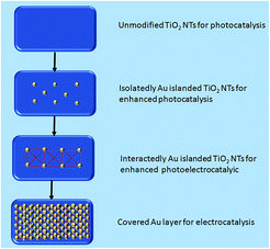 | ||
| Scheme 1 Isolated/interacting Au islands on TiO2 NTs for photocatalytic/photoelectrocatalytic switching. | ||
Characterization
Using a field launch scanning electron microscope (SEM, Zeiss, Sigma HV), we observed the structures of the nanotubes and the morphologies of the Au/TiO2 NTs. The crystal structures of the samples were obtained by X-ray diffraction (XRD, Rigaku, D/MAX2200). The surface element composition and element mass fraction of the Au/TiO2 NTs were determined by an energy dispersive spectrometer (EDS). Elemental composition of the bulk was measured by Inductively Coupled Plasma-Atomic Emission Spectrometry (ICP-AES, Agilent 730). The samples (0.07 g) were dissolved by aqua regia and then were fixed at a capacity of 50 mL before ICP-AES detection. The composition and chemical changes of the surface elements of the samples under the action of an aluminum ka radiation source at 150 W were investigated by X-ray photoelectron spectroscopy. The light absorption properties of the Au/TiO2 NT catalyst were studied by a small diffuse reflectance spectrometer (DRS) (UV-2550), Shimadzu, Japan, and BaSO4 was used as a reference.Photocatalytic/photoelectrocatalyic (PC/PEC) degradation of NB
In the experiment, a 300 W mercury lamp with an irradiation distance of 10 cm was used as the ultraviolet light source as a substitute for a solar light. In order to disperse ultraviolet rays uniformly and improve the utilization rate of light, tin foil was packed inside the reactor. Simulated organic pollutant wastewater (30 mL, 5 g L−1 Na2SO4, 0.2 g L−1 NB) and the Au/TiO2 NTs were placed in a quartz device with circulating water, and the adsorption and desorption equilibrium of the solution was reached by stirring at room temperature for 30 min. A PEC system was used with the Au/TiO2 NTs as the working anode electrode and Pt as the cathode electrode with a bias voltage of 1.2 V. The degradation rate of NB was measured by a UV-vis spectrophotometer (Shimazu, UV-1700) once per 30 min measurement over 2 hours.Results and discussion
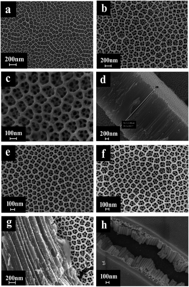
In a photocatalytic reaction, the PC activity is determined by the ability of generating electron–hole pairs after light absorption, thereby generating a secondary reaction of free radicals (e.g. hydroxyl radicals: ˙OH).25 The PEC takes advantage of the heterogeneous photocatalytic process by adding a voltage of 1.2 V to the photoelectrode which supports the catalyst. This configuration allows for the more effective separation of photogenerated charges due to light irradiation, with the energy being higher compared to the bandgap energy of the semiconductor, which separates the charge generated by light from the energy generated by the semiconductor bandgap. Therefore, the lifetime of photogenerated electron–hole pairs can be greatly prolonged.26 Herein, the catalyst was both PC and PEC and could be switched, which was determined by the amount of Au loaded on the TiO2 NTs.The SEM images in Fig. 1 were taken to analyze the morphologies of the Au/TiO2 NTs with isolated/interacting Au islands on the TiO2 NTs for a switching PC/PEC application. A honeycombed structure with a highly regular hexagonal structure can be observed on the surface of the TiO2 NTs, meanwhile each hexagon contained 6–8 evenly monodispersed nanotubes. As shown in Fig. 1d, the TiO2 NTs exhibit a regularly arranged length of TiO2 NTs with a uniform size distribution of around 3 μm. Compared with the structure of the TiO2 NTs shown in Fig. 1a, it can be observed that the appearance of the TiO2 NTs was not changed after spraying Au under vacuum conditions. The mouth of the nanotubes was thickened by spraying Au, and the active catalytic area was significantly increased because of the Au islands on the surface, which have a high degree of dispersion as isolated Au islands. With the prolongation of the spraying time, the tube mouth became thicker, and the number and the size of the Au islands inside the tube and on the surface of the TiO2 NTs increased correspondingly. In addition, by prolonging the spraying time, the isolated Au islands gradually transform into interacting Au islands, and the photocatalytic performance is significantly enhanced. It can be seen from Fig. 1h that when the spraying time was 60 s, the nanotubes disappeared because the Au islands became larger in size and more in quantity to cover the tube mouth of the TiO2 NTs. The covered Au layer had a positive effect on the electrocatalysis by increasing the electron transport through the Ti sheet to the surface of TiO2 NTs.
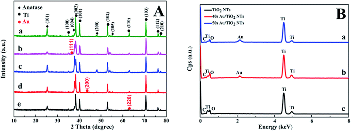
Fig. 2A shows the XRD pattern of the Au/TiO2 NTs with Au spraying times from 20 s to 60 s. The crystallographic structure of the Au/TiO2 NT heterostructures was inspected by XRD. According to the standard diffraction card (JCPDS 21-1272), we could observe the diffraction peaks at 25.43°, 37.92°, 48.03°, and 53.97° respectively corresponding to the (101), (004), (200), and (105) crystal planes of anatase TiO2. The diffraction peaks at 38.34°, 40.2°, 53.1°, 70.8°, and 75.8° separately correspond to the (002), (101), (102), (103), and (112) planes, which were in extreme coincidence with the Ti metal phase (JCPDS 44-1294), and the existence of the titanium substrate was proved. Furthermore, it was concluded that the Au/TiO2 NTs were composed of anatase TiO2 and Ti. The XRD patterns showed no distinguishable difference among the TiO2 NTs prepared with different spraying times, and all samples were in accordance with the anatase-rutile mixed phase of TiO2. The anatase phase of the nanotubes was not significantly changed after spraying Au, which also indicated that the crystal structure of the Au/TiO2 NTs did not change after spraying the Au nanoparticles. In Fig. 2A, the peaks at 38.21°, 44.32°, and 63.80° separately correspond to the (111), (200) and (220) planes of the metallic Au phase (JCPDS 65-2870), meanwhile due to the small loading amount of Au, a smaller diffraction peak of Au is showed in Fig. 2B. The successful preparation of the Au/TiO2 NT photocatalyst was further verified. Fig. 2B shows the EDS spectra acquired for the Au/TiO2 NTs and the TiO2 NTs, which show the Au peaks, meanwhile both Ti and O peaks can be seen in the samples. The mass fraction of each element in the sample by measuring the EDS is shown in Table S1 in the ESI,† and it also solidly proved the existence of Au on the surface of the TiO2 NTs. Since EDS can only be used for qualitative and quantitative analysis of the microelements on the surface of the samples, in order to further determine the whole element composition, ICP-AES was used to detect the bulk composition of the samples. The mass fraction of each element can be seen in Table 1, from which we can notice that the Au/TiO2 NTs are both composed by Ti, Au and O, which is in agreement with the expectations. The mass fraction of Ti is slightly more than that of Au. The reason for this is that the nanotubes were on the surface of the titanium substrate and the sprayed Au was mainly concentrated on the nanotubes, and the titanium substrate was completely dissolved in the solution during the measurement of ICP-AES. Au was also detected in the Au/TiO2 NTs which suggests that Au was successfully introduced into the TiO2 NTs.
| Samples | Ti | O | Au |
|---|---|---|---|
| 20 s Au/TiO2 NTs | 99.72 | 0.2701 | 0.0099 |
| 40 s Au/TiO2 NTs | 99.56 | 0.4242 | 0.0158 |
| 50 s Au/TiO2 NTs | 99.66 | 0.3219 | 0.0181 |
The transient photocurrent responses of the TiO2 NTs and the Au/TiO2 NT heterostructures under intermittent UV-light illumination were detected and are shown in Fig. 3, which illustrates that the photocurrent was enhanced obviously when the light was turned on and was decreased rapidly to zero when the light was turned off.27 The photocurrent density of the Au/TiO2 NTs with a spraying time of 40 s was 1.5 times higher than that of the unmodified TiO2 NTs (0.28 mA cm−2), which reached about 0.4 mA cm−2. The deposition of the Au islands significantly improved the separation efficiency of the photo-generated electron–hole pairs. Furthermore, with periodic UV irradiation, significantly increased/decreased currents were observed with excellent reproducibility in all cycles. The results proved that the Au islands can trap the photoinduced electrons of the TiO2 NTs and enhance the photocurrent response of the Au/TiO2 NTs, revealing the more efficient separation of the hole–electron pairs and longer lifetime of the photo-generated charge,28 thus efficiently improving the PC activity of organic pollutant degradation.
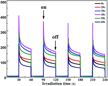 | ||
| Fig. 3 Photocurrent response of the two-step TiO2 NTs and the Au/TiO2 NTs at an applied potential of 0.5 V under the irradiation of UV light and a Ag/AgCl electrode was used as a reference electrode. | ||
To further confirm the form of the Au islands, XPS was used to analyze the surface elemental compositions and chemical changes of the Au/TiO2 NTs. The XPS pattern of the Au/TiO2 NTs shown in Fig. 4a, which presented the obvious featured signals of Ti 2p, Au 4f, O 1s, and C 1s, was detected to confirm the elements of the sample, and indicated the successful loading of metal Au on TiO2 NTs. Meanwhile, high-resolution Ti 2p spectra (Fig. 4b) showed two peaks of Ti 2p3/2 at 458.5 eV and Ti 2p1/2 at 464.2 eV that correspond to Ti4+ species, which can effectively hinder the recombination of electrons and holes. High-resolution O 1s spectra (Fig. 4d) showed peaks at 531.53 eV and 532.52 eV, which were attributed to Ti–OH and C–OH species, and this was consistent with the C 1s spectrum peak at 288.60 eV. High-resolution C 1s spectra (Fig. 4e) obviously showed with two peaks at 284.60 eV and 288.60 eV, which were attributed to C–C/C–H and OH–C![[double bond, length as m-dash]](https://www.rsc.org/images/entities/char_e001.gif) O species from carbon dioxide in the atmosphere during the calcination process or the EG of the electrolyte. We can also observe the featured peaks of Au 4f7/2 located at 83.28 eV and Au 4f5/2 located at 87.05 eV (Fig. 4c), which were not faithfully consistent with those of metallic Au.29 There was a significant negative shift (ca. 0.7 eV) of the featured peaks of Au 4f7/2 located at 84.00 eV and Au 4f5/2 located at 87.45 eV, which can be attributed to the formed Schottky junctions amongst the TiO2 NTs and Au, which resulted in a fast photoelectron transfer from the oxygen vacancies of TiO2 to the Au(0) nanoparticles and an efficient separation of the photogenerated electrons from holes.30
O species from carbon dioxide in the atmosphere during the calcination process or the EG of the electrolyte. We can also observe the featured peaks of Au 4f7/2 located at 83.28 eV and Au 4f5/2 located at 87.05 eV (Fig. 4c), which were not faithfully consistent with those of metallic Au.29 There was a significant negative shift (ca. 0.7 eV) of the featured peaks of Au 4f7/2 located at 84.00 eV and Au 4f5/2 located at 87.45 eV, which can be attributed to the formed Schottky junctions amongst the TiO2 NTs and Au, which resulted in a fast photoelectron transfer from the oxygen vacancies of TiO2 to the Au(0) nanoparticles and an efficient separation of the photogenerated electrons from holes.30
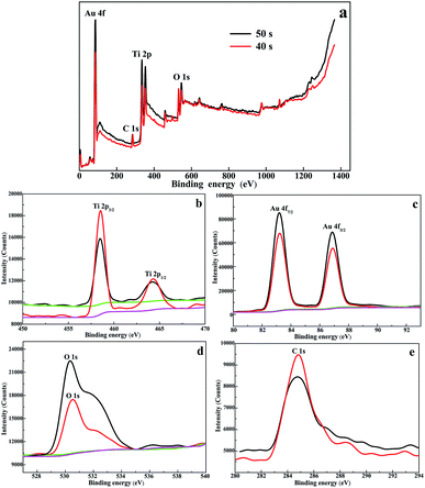 | ||
| Fig. 4 (a) XPS survey spectra of the 40 s Au/TiO2 NTs and the 50 s Au/TiO2 NTs heterostructures and high-resolution spectra of (b) Ti 2p, (c) Au 4f, (d) O 1s, and (e) C 1s. | ||
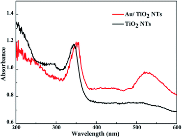
Fig. 5 presents the UV-vis DRS spectra of the original TiO2 NTs and the Au/TiO2 NTs with a spraying time of 40 s. Due to the electron transition from the valence band (VB) to the conduction band (CB), the sample has a strong absorption band in the ultraviolet region of 200–400 nm.31 In addition, the Au/TiO2 NT samples exhibit an obvious absorption peak at 520 nm in the visible region, resulting from the SPR of the Au islands. TiO2 is represented by a negative conductive band at ca. −0.50 V versus the normal hydrogen electrode (NHE), while the Fermi energy level of the Au nanoparticles is positioned at ca. +0.45 V versus the NHE.32 The Au/TiO2 NTs after the loading of Au can make the Fermi energy level of the Au nanoparticles move to more negative potentials and TiO2 in the direction of more positive potentials, ultimately reaching a new Fermi energy level equilibrium. It has been reported that when Au nanoparticles come into contact with the surface of the TiO2 NTs, the Fermi energy level of the Au/TiO2 NTs is reduced by about 0.19 eV.33 Due to the SPR of the Au islands, the high energy plasmon electrons of the Au nanoparticles on the Au/TiO2 NTs can transfer to the conduction band of the TiO2 NTs, and then enhance the catalytic performance of the photocatalyst.34
The switched PC/PEC performances through the isolated/interacting Au islands on the TiO2 NTs were estimated by the degradation of nitrobenzene solution as refractory organic wastewater at ambient room conditions. It has been established that both the PC and PEC degradation of nitrobenzene can be attributed to a pseudo-first-order reaction, ln(C0/C) = kat, when C0 is very small, and where ka is the first-order reaction rate constant. Significantly, ka increases gradually with the prolongation of Au spraying time, and ka decreases as Au loading continues to increase. The degradation rates of nitrobenzene solution with different spraying times are summed up in Fig. 6c. It can be concluded that the degradation rate of nitrobenzene with unmodified TiO2 NTs was 28.35%, although the rate was not very effective, proving that unmodified Au island degradation was driven by the PC process. The enhancement of photoabsorption and the improvement of the quantum efficiency were important factors for improving the PC activity.35 When the Au islands were introduced into the TiO2 NT surface, the degradation rate was increased very significantly, and with an increase in the Au islands, the degradation rate was enhanced gradually, and reached a maximum of 50.89% when the spraying time was 40 s. This also verifies the authenticity of isolated Au islands on the TiO2 NTs for enhanced photocatalysis. However, when the spraying time continued to increase, the PC degradation rate was even lower than that of the TiO2 NTs. The excessive loading of Au islands blocked the nozzle of the nanotube, causing an abatement of the light passing through and the active sites of the photocatalyst, which led to a decrease in the degradation rate. Therefore, a spraying time of 40 seconds with isolated Au islands on the TiO2 NTs was proved to be optimal for PC activity with the highest PC degradation rate.
To be more efficient in refractory organic wastewater treatment, the photoelectrocatalyst was proposed to enhance the degradation rate. Under the combined action of photocatalysis and bias voltage, the separation efficiency of the photo-generated charge was improved obviously. The interacting Au islands on the TiO2 NTs resulted in enhanced photoelectrocatalysis and the covered Au layer resulted in electrocatalysis. Herein, the catalyst applied to photocatalysis was switched for optimal PEC activity through the interacting Au islands on the TiO2 NTs, which had the highest PEC degradation rate. The PEC properties of the Au/TiO2 NTs were determined by a biased potential of 1.2 V under the electrolysis voltage of water, with the kinetic curve shown in Fig. 6b and the degradation rate shown in Fig. 6c.
It was obvious that the degradation rate increased up to 68.7% when the spraying time was 50 s, which means the external voltage can be driven away from the electrons from the Au islands and thus promote PEC degradation. This can be explained as Au nanoparticles can be easily captured by the photogenerated electrons and can lead to charge transport and diminished charge recombination, which then prolongs the lifetime of electron–hole pairs. Therefore, a spraying time of 50 seconds with the interacting Au islands on the TiO2 NTs was proved to enhance PEC activity with the highest PEC degradation rate. Furthermore, when the spraying time continued to increase and the degradation rate of nitrobenzene was decreased, the big Au islands formed a gold layer in the pores instead of promoting charge transfer and reducing charge recombination, thus reducing quantum efficiency. The existence of a large number of Au islands in the pores also reduced the mass transfer rate and reaction rate. These factors will result in the reduction of photocatalysis efficiency.29
It is well known that the stability of catalysts is particularly important for achieving large-scale industrialization of processes, so cycling experiments were conducted, as shown in Fig. 7. It is obvious that after five circulations, the degradation rate of nitrobenzene was basically the same as that of the first one. The results illustrated that the photocatalyst did not show obvious deactivation even during five consecutive reactions, which indicated the excellent stability of the Au/TiO2 NTs. Moreover, the TiO2 NTs were a kind of direct up-growth on the Ti foil and have broad application prospects in actual production processes compared with particle or powder catalysts.
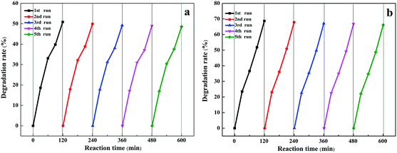 | ||
| Fig. 7 Photostability and catalytic stability of (a) 40 s Au/TiO2 NTs and (b) 50 s Au/TiO2 NTs for photoelectrocatalytic degradation of nitrobenzene. | ||
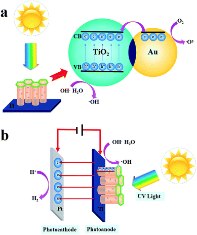
The PC and PEC mechanism of the Au/TiO2 NTs is shown in Scheme 2. When the Au/TiO2 NTs were exposed to ultraviolet light, the electrons in the valence band were excited to transition to the conduction band and gathered on the surface, and then departed an aspiring aperture in the valence band, and thus the photogenerated electron–hole pairs were formed. The loading of Au nanoparticles on TiO2 NTs can increase the Fermi energy level difference between the Au nanoparticles and the TiO2 NTs, respectively, and finally reach a new Fermi level equilibration.36 When a transistor radio touches a metal, the electrons flow from the Au to the semiconductor. The Schottky barrier existing between TiO2 and the metal will result in a higher potential gradient, thus the photo-generated electrons in the Au nanoparticles will further migrate to the conduction band,37 afterward O2 reduces to form a superoxide anion (˙O2−), and the electron–hole in the valence band is oxidized with water (H2O) or an adsorbed hydroxyl group to form a hydroxyl radical (˙OH), which is significant for the degradation of nitrobenzene. Thus, the utilization rate of light was improved and the PC activity of the Au/TiO2 NTs was further enhanced. Furthermore, a plasma resonance reaction existed on the Au nanoparticles, and precious metals can act as electron capture centers, which promoted the separation of photo-generated electrons and holes.38
A tentative photoelectrocatalytic mechanism is proposed in Scheme 2(b) to understand the reaction process. Due to the addition of a 1.2 V bias voltage, the Au/TiO2 NTs could act as a photoanode, in which an oxidation reaction will occur, and the counter electrode Pt will run a reduction reaction and act as a photocathode. On the one hand, in the process of photoelectrocatalysis, the effective charge transfer could facilitate the separation of the photo-generated electron–hole pairs.39 The TiO2 NTs could facilitate the directional movement of the photo-generated charges. On the other hand, under the action of the external voltage, the electrons move along the TiO2 NTs to the Ti substrate, eventually reaching the reduction reaction at the counter electrode, which increases the lifetime of the active electrons, thus accelerating the formation of photo-generated electron pairs and finally resulting in an enhanced PEC performance. The PEC process accelerated the formation of photo-generated electron pairs due to the addition of a 1.2 V bias voltage, and the interacting Au islands on the TiO2 NTs enhanced PEC performance.
Conclusions
To sum up, we proposed a simple interface method for preparing Au island modified TiO2 NTs for PC/PEC switching, and evaluated their catalytic activity through the degradation of nitrobenzene wastewater, which indicated that the optimal PC and PEC efficiencies were with 40 s and 50 s sputtering times, respectively. Compared with the unloaded TiO2 NTs, all of the samples exhibited preferable catalytic activity, which can be interpreted as Au islands capturing a photo-generated electron, promoting charge transport and diminishing charge recombination and thus the catalytic activity was remarkably enhanced. The results revealed that PC/PEC activity based on isolated/interacting Au islands on the TiO2 NTs switched the reactive efficiency of nitrobenzene, confirming superior PC and PEC activity. Our work reports a switching catalyst for selective photocatalysis/photoelectrocatalysis applications by virtue of processing simplicity and flexibility for the degradation of refractory organic pollutants.Conflicts of interest
There are no conflicts to declare.Acknowledgements
This work was supported jointly by the National Natural Science Foundation of China (project no. 21808030), the China Postdoctoral Science Foundation (2018M641803) and Heilongjiang Postdoctoral Science Foundation, the University Nursing Program for Young Scholars with Creative Talents in Heilongjiang Province (UNPYSCT2018044), the Heilongjiang Natural Science Fund (QC2018009) and the Northeast Petroleum University peiyu Funding (2017PYQZL-07).Notes and references
- G. Ai, H. Li, S. Liu, R. Mo and J. Zhong, Adv. Funct. Mater., 2015, 25(35), 5706 CrossRef CAS.
- Q. Kang, T. Wang, P. Li, L. Liu, K. Chang, M. Li and J. Ye, Angew. Chem., Int. Ed., 2015, 54, 841–845 CrossRef CAS PubMed.
- C. A. D’Amato, R. Giovannetti, M. Zannotti, E. Rommozzi, S. Ferraro, C. Seghetti, M. Minicucci, R. Gunnella and A. D. Cicco, Appl. Surf. Sci., 2018, 441, 575 CrossRef.
- G. Zhang, H. Miao, X. Hu, J. Mu, X. Liu, T. Han, J. Fan, E. Liu, Y. Yin and J. Wan, Appl. Surf. Sci., 2016, 391, 345–352 CrossRef.
- K. Zhu, N. R. Neale, A. Miedaner and A. J. Frank, Nano Lett., 2007, 7, 69 CrossRef CAS PubMed.
- J. R. Jennings, A. Ghicov, L. M. Peter, P. Schmuki and A. B. Walker, J. Am. Chem. Soc., 2008, 130, 13364–13372 CrossRef CAS PubMed.
- D. Gu, H. Wu, Y. Zhu and B. Wang, RSC Adv., 2015, 5, 57937–57942 RSC.
- D. Gu, B. Wang, Y. Zhu and H. Wu, Aust. J. Chem., 2015, 69, 343 CrossRef.
- A. Hagfeldt, G. Boschloo, L. Sun, L. Kloo and H. Pettersson, Chem. Rev., 2010, 110, 6595 CrossRef CAS PubMed.
- L. Brus, Acc. Chem. Res., 2008, 41, 1742 CrossRef CAS PubMed.
- T. N. Ravishankar, M. D. O. Vaz and T. Ramakrishnappa, et al. , RSC Adv., 2017, 7(7), 43233–43244 RSC.
- T. K. Rahul and N. Sandhyarani, ChemNanoMat, 2017, 3(7), 503–510 CrossRef CAS.
- S. Kitagawa, H. Yamazaki, H. Ai, M. Nishiyama and K. Watanabe, Photonic Instrumentation Engineering III, International Society for Optics and Photonics, 2016, vol. 9754, p. 97541B, DOI:10.1117/12.2212421.
- Y. H. Tseng, I. G. Chang, Y. Tai and K. W. Wu, J. Nanosci. Nanotechnol., 2012, 12, 416 CrossRef CAS PubMed.
- K. Tada, H. Koga, A. Hayashi, Y. Kondo, T. Kawakami, S. Yamanaka and M. Okumura, Appl. Surf. Sci., 2017, 411, 149–162 CrossRef CAS.
- J. Priebe, J. Radnik and C. Kreyenschulte, et al. , ChemCatChem, 2017, 9(6), 1025–1031 CrossRef CAS.
- W. Wang, M. Lai and J. Fang, et al. , Appl. Surf. Sci., 2018, 439, 430–438 CrossRef CAS.
- M. Haruta, Faraday Discuss., 2011, 152, 11–32 RSC.
- C. Pu, J. Wan, E. Liu, Y. Yin, J. Li, Y. Ma, J. Fan and X. Hu, Appl. Surf. Sci., 2017, 399, 139 CrossRef CAS.
- S. M. Yoo, S. B. Rawal, E. L. Ji, J. Kim, H. Y. Ryu, D. W. Park and I. L. Wan, Appl. Catal., A, 2015, 499, 47–54 CrossRef CAS.
- Y. Chen, H. Li, W. Liu, Y. Tu, Y. Zhang, W. Han and L. Wang, Chemosphere, 2014, 113, 48–55 CrossRef CAS PubMed.
- Y. P. Li, H. B. Cao, C. M. Liu and Y. Zhang, J. Hazard. Mater., 2007, 148, 158–163 CrossRef CAS PubMed.
- D. Gu, N. Shao and Y. Zhu, et al. , J. Hazard. Mater., 2017, 321, 703–710 CrossRef CAS PubMed.
- D. Gu, Y. Wang, Z. Li, Y. Liu, B. Wang and H. Wu, RSC Adv., 2016, 6, 63711 RSC.
- R. Giovannetti, C. A. D. Amato, M. Zannotti, E. Rommozzi, R. Gunnella, M. Minicucci and A. D. Cicco, Sci. Rep., 2015, 5, 17801 CrossRef CAS PubMed.
- G. G. Bessegato, T. T. Guaraldo, J. F. D. Brito, M. F. Brugnera and M. V. B. Zanoni, Electrocatalysis, 2015, 6, 415–441 CrossRef CAS.
- N. Zhang, Y. Zhang, X. Pan, X. Fu, S. Liu and Y. J. Xu, J. Phys. Chem. C, 2012, 116, 18023 CrossRef CAS.
- W. Ling, L. Fang, Y. Xu, J. W. Zhang, D. Zhang, G. Li and H. Li, Appl. Catal., B, 2015, 164, 217 CrossRef.
- H. Li, Z. Bian, J. Zhu, Y. Huo, H. Li and Y. Lu, J. Am. Chem. Soc., 2007, 129, 4538–4539 CrossRef CAS PubMed.
- Z. Zhang, L. Zhang, M. N. Hedhili, H. Zhang and P. Wang, Nano Lett., 2013, 13, 14–20 CrossRef CAS PubMed.
- N. Abdullahi, E. Saion, A. H. Shaari, N. M. Al-Hada and A. Keiteb, PLoS One, 2015, 10, e0125511 CrossRef PubMed.
- Long, J. Chang, H. Gu, Q. Xu, J. Fan and L. Wang, Energy Environ. Sci., 2014, 7(3), 973–977 RSC.
- Z. Liu, X. Gong, J. Kohanoff, C. Sanchez and P. Hu, Phys. Rev. Lett., 2003, 91(26), 266102 CrossRef PubMed.
- Nie, J. Schneider and F. Sieland, et al. , RSC Adv., 2018, 8(46), 25881–25887 RSC.
- X. Zhou, G. Liu, J. Yu and W. Fan, J. Mater. Chem., 2012, 22, 21337–21354 RSC.
- Q. He, H. Sun and Y. Shang, et al. , Appl. Surf. Sci., 2018, 441, 458–465 CrossRef CAS.
- Z. W. Seh, S. Liu, M. Low, S. Y. Zhang, Z. Liu, A. Mlayah and M. Y. Han, Adv. Eng. Mater., 2012, 24, 2310–2314 CAS.
- M. A. Garcia, J. Phys. D: Appl. Phys., 2011, 44, 283001 CrossRef.
- Q. Wei, F. Xiong and S. Tan, Adv. Mater., 2017, 29(20) DOI:10.1002/adma.201602300.
Footnote |
| † Electronic supplementary information (ESI) available. See DOI: 10.1039/c8ra09160a |
| This journal is © The Royal Society of Chemistry 2019 |

