 Open Access Article
A green approach to prepare hierarchical porous carbon nanofibers from coal for high-performance supercapacitors†
Fenglian Tong,
Wei Jia,
Yanliang Pan,
Jixi Guo *,
Lili Ding,
Jingjing Chen and
Dianzeng Jia*
Laboratory of Energy Materials Chemistry, Ministry of Education, Key Laboratory of Advanced Functional Materials, Autonomous Region, Institute of Applied Chemistry, Xinjiang University, Urumqi, 830046, Xinjiang, P. R. China. E-mail: jxguo1012@163.com; jdz@xju.edu.cn; Fax: +86-991-8588883; Tel: +86-991-8583083
First published on 20th February 2019
Abstract
A green method is designed to obtain hierarchical porous carbon nanofibers from coal. In the work, deionized water, coal, polyvinyl alcohol and Pluronic F127 are used as the aqueous solution, carbon source, spinning assistant and soft template for spinning, respectively. As electrode materials for supercapacitors, the obtained hierarchical porous carbon nanofibers exhibit a high specific capacitance of 265.2 F g−1 at 1.0 A g−1 in 6 M KOH, a good rate performance with a capacitance of 220.3 F g−1 at 20.0 A g−1 with the retention of 83.1% and a superior cycle stability without capacitance loss after 20![[thin space (1/6-em)]](https://www.rsc.org/images/entities/char_2009.gif) 000 charge/discharge cycles at 10.0 A g−1. Compared with the carbon nanofibers constructed without Pluronic F127, the enhanced electrochemical performance of the sample benefits from a larger contact surface area and the mesoporous structure formed by decomposition of Pluronic F127 and good structural stability. This work not only provides a green route for high-value utilization of coal in energy storage, but also paves a new way to make hierarchical porous carbon nanofibers from coal for supercapacitor electrodes with high specific capacitance and long cycle life.
000 charge/discharge cycles at 10.0 A g−1. Compared with the carbon nanofibers constructed without Pluronic F127, the enhanced electrochemical performance of the sample benefits from a larger contact surface area and the mesoporous structure formed by decomposition of Pluronic F127 and good structural stability. This work not only provides a green route for high-value utilization of coal in energy storage, but also paves a new way to make hierarchical porous carbon nanofibers from coal for supercapacitor electrodes with high specific capacitance and long cycle life.
1. Introduction
Due to their unique physical and chemical properties, carbon-based nanomaterials have attracted much attention, which make them have broad application prospects in changing the future of various important applications.1,2 The strong demand for environmentally-friendly and inexpensive synthesis strategies to develop carbon nanomaterials has driven much of the global effort. Precursors used to grow carbon-based nanomaterials play a key role in the success of evolving technologies. Most traditional synthetic technologies use expensive carbon raw materials, such as hydro-carbons and graphite, which leads to high cost production, limiting their commercialization. Coal is a rich and cheap natural resource, which is considered as a green and feasible substitute for the efficient production of carbon nanomaterials. So far, the researchers have done a lot of research to apply coal to energy storage. However, mass production of high-quality carbon nanomaterials through environmentally-friendly and inexpensive strategies remains a significant challenge. Considering the above factors and the factors affecting the performance of supercapacitors,3–6 the key to electrochemical performance of supercapacitors is to design a green, simple and efficient method to obtain hierarchical porous carbon materials with both high specific surface area and reasonable pore structure, such as carbide-derived carbon,7 carbon onions,8 carbon nanotubes (CNTs),9 carbon aerogels,10 template porous carbon11 and carbon nanofibers (CNFs).12–14It is common knowledge that CNFs as one of the typical one-dimensional nanomaterials not only provide pathways shortened for the rapid transportation of electrons, but also facilitate the penetration of electrolyte along the direction of the fiber diameter, as well as supplying a high active area to electrochemical reactions. Thus, the unique 1D nanostructure can contribute high performance as electrode materials for electrical double-layer capacitors (EDLCs). The CNFs are also relatively easy to be prepared by electrospinning, which is regarded as one of the most effective methods to prepare carbon nanofibers due to both simple operation and easily controllable experimental conditions.15,16 Therefore, many studies have focused on exploiting hierarchical porous carbon nanofibers (HPCNFs) to improve electrochemical properties. At present, most of the HPCNFs electrode materials are produced by electrospinning precursor solution containing pore-forming agent, which mainly include soft template,17–22 hard template23–26 and soluble salt.27,28 Comparing with the hard template and the soluble salt, the soft template can be directly decomposed during the carbonization process without etching procedure by using either toxic or corrosive chemical, which are harmful to the environment. Among soft template agents, Pluronic amphiphilic triblock copolymers such as F127 is extensively used for the fabrication of mesoporous carbon due to their amphiphilic nature.17,29–31 Up to now, a few methods have been reported for the direct synthesis of porous CNFs by carbonization of polymers, but it is still a great challenge and highly desirable to design a simple approach for the controllable synthesis HPCNFs.
In our work, water was used as spinning solvent instead of organic solvent, so that it can effectively prevent the generation of the toxic gas in spinning process. The relatively cheap polyvinyl alcohol is made as a spinning aid, and its carbon residue after carbonization is very low, so the coal is the main carbon source.31 A facile template F127 is directly decomposed and forms mesopores in the process of carbonation.32 As a result, the sample shows a high capacitance of 265.2 F g−1 at a scan rate of 1.0 A g−1 serving as the binder-free electrodes in EDLCs, which is superior to that of the samples (170 F g−1) without the F127. More significantly, the optimal sample delivers an outstanding rate capability of 220.3 F g−1 at a scan rate of 20.0 A g−1 and maintains over 100% of the initial capacitance after 20![[thin space (1/6-em)]](https://www.rsc.org/images/entities/char_2009.gif) 000 cycles at 10.0 A g−1. The material with hierarchical porous structure is a potential electrode material for energy conversion and storage. And this work provides a green way for high-value utilization of coal in energy storage.
000 cycles at 10.0 A g−1. The material with hierarchical porous structure is a potential electrode material for energy conversion and storage. And this work provides a green way for high-value utilization of coal in energy storage.
2. Methods
2.1 Materials
Coal was obtained from Heishan, Xinjiang, China. PVA (polyvinyl alcohol, 1788, alcoholysis degree: 87.0–89.0% (mol mol−1)) and Pluronic F127 were purchased from Sigma-Aldrich, and KOH (potassium hydroxide, 95.0%, Samchun) was used as a neutralizer. Deionized water was used as the solvent in the whole article.2.2 Synthesis of HPCNFs
Raw coal powers were dealt as previously reported by our group.13 0.8 g oxidized coal was dissolved in 10 mL distilled water by ultrasonication and neutralized with 0.1 g KOH to obtain a homogeneous dispersion, followed by addition of 0.4 g F127 was stirred into the above solution. After the temperature of the resultant solution was increased to 80 °C, 0.8 g PVA was mixed into the mixture solution by stirring at 80 °C for 24 h to form a homogeneously dispersed solution. Then, the black solution was drawn into a syringe (10 mL) with a stainless-steel nozzle served as an electrode. The fibers were collected on an aluminium foil, which was served as the counter electrode. The receiving distance was 18 cm apart. Meanwhile a potential of 25 kV, feeding rate of 0.06 mm min−1 and temperature of 25 °C were applied between them, respectively. After electrospinning, the as-prepared nanofibers were placed in an oven and heated at a rate of 1 °C min−1 from room temperature up to 200 °C in air atmosphere, and then were stabilized for 2 h at the final temperature. Afterwards, the nanofibers were heated at 400 °C for 1 h with a heating rate of 2 °C min−1 in a flow of N2, followed by a further thermal annealing process at 900 °C for 2 h at a heating rate of 5 °C min−1. The little potassium salt was washed with distilled water several times. The as-obtained sample was designated as CNFs-F2-900.At the same time, three other kinds of the spinning solution with different mass ratios of oxidized coal/PVA/F127 (0.8 g/0.8 g/0.0 g, 0.8 g/0.8 g/0.2 g, 0.8 g/0.8 g/0.6 g and 0.8 g/0.8 g/0.8 g, respectively) were prepared and synthesized by a similar procedure of CNFs-F2-900. These are designated as CNFs-F0-900, CNFs-F1-900, CNFs-F3-900 and CNFs-F4-900 respectively. For the two others of coal based HPCNFs annealed at 800 °C (denoted as CNFs-F2-800) or 1000 °C (CNFs-F2-1000), were carbonized in N2 atmosphere through a two-stage heating process. They were first heated at 400 °C for 1 h with a heating rate of 2 °C min−1, followed by a further thermal annealing process at 800 °C (or 1000 °C) for 2 h with a heating rate of 5 °C min−1.
2.3 Characterization techniques
Thermogravimetric analysis (TGA) was tested by using a NETZSCH STA449F3-QMS403C instrument under N2. The morphology and structure features of the product were conducted by using field emission scanning electron microscopy (FESEM Hitachi S-4800), by transmission electron microscopy (TEM Hitachi H-600) and high resolution transmission electron microscope (HRTEM JEM 2100). The Raman spectra of HPCNFs were recorded on a Raman spectroscopy (Bruker SENTERRA, 532 nm laser). Powder X-ray diffraction (XRD, Bruker D8) measurements were conducted to research the crystal structure of the HPCNFs. X-ray photoelectron spectroscopy (XPS, ESCALAB250Xi) analysis was performed to detect elemental of the composite. The HPCNFs samples were also recorded by nitrogen adsorption–desorption at 77 K (Autosorb-IQ, Quantachrome, USA).2.4 Electrochemical property test
The HPCNFs were directly made into binder-free working electrodes, the size of which was 1 cm × 1 cm (about 2.5 mg). The supercapacitors were tested by cyclic voltammetry (CV) on a CHI 660D electrochemical workstation (Chen Hua, China), where galvanostatic charge–discharge and electrochemical impedance spectroscopy (EIS) were tested. In a three-electrode cell, platinum foil and the saturated calomel electrode (SCE) were used as counter and reference electrodes, respectively. The specific capacitance (Cs) of the HPCNFs electrode was calculated via eqn (1)| Cs = IΔt/(mΔV) | (1) |
In the two-electrode system, the specific capacitance (C) values were obtained via eqn (2)
| C = IΔt/(MΔV) | (2) |
3. Result and discussion
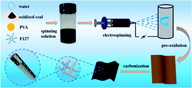
The details for the preparation of HPCNFs are showed in Fig. 1. Firstly, the oxidized coal was dissolved into the distilled water under ultrasonication and neutralized with a little of KOH, the F127 were also added into the above solution. After the temperature of the resultant solution was increased to 80 °C, the PVA was mixed into the mixed solution and was stirred at 80 °C for 24 h to form a uniform spinning solution. Secondly, the nanofibers were made by an electrostatic spinning method. Thirdly, the nanofibers were obtained by preoxidation and then carbonization. The formation of mesopores may be as follows: (i) the F127 forms micelles in the black solution and the hydrophilic PEO chains are around the micelle center, and the hydrophobic group is outward, so the size of micelles gets bigger at higher temperature. (ii) When the PVA is added into the black solution, hydroxyl groups of PVA form hydrogen bonds with F127 micelles. (iii) the F127 micelles are carbonized to produce the mesopores. The process is different from the self-assembly of F127.32 Thus the resulting mesopores are irregular arrangement.The contents of carbon in the samples were measured by thermogravimetric (TG) curves as shown in Fig. S1.† From the TG curves above, the mass losses of oxidized coal, PVA, F127 and precursor CNFs-F4-900 are 53.4%, 97.2%, 98.8% and 57.4%, respectively. The detected carbon contents of 94% in the sample are provided by oxidized coal, indicating that the obtained nanofibers are real coal-based carbon materials. In other words, the residual carbon comes mainly from coal in the carbon nanofibers.
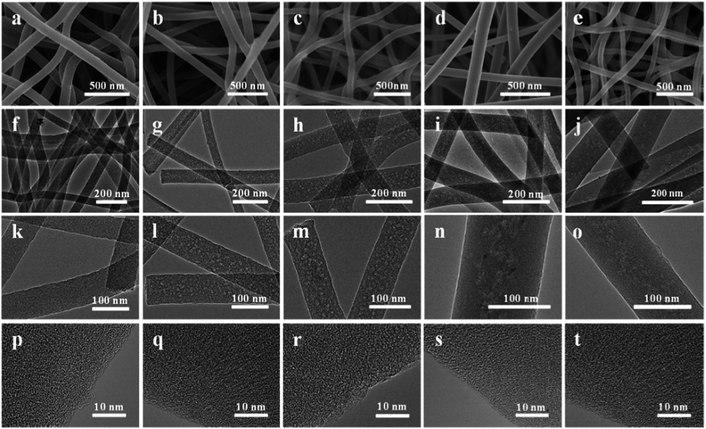
The morphologies of the resultant HPCNFs were characterized by using SEM and TEM. The HPCNFs shown in Fig. 2a–e present a long fibrous morphology and homogeneous diameter distributions in the range of 70–150 nm. As illustrated in Fig. 2f–o, there are clearly visible mesopores in the samples except for CNFs-F0-900, which is due to the effect of pore-forming agent F127. Furthermore, the mesopores in the sample CNFs-F2-900 are more uniform distribution than the other samples, which could be attributed to the moderate amount of pore forming agents F127. In the sample CNFs-F1-900 a small amount of F127 could be not enough to be used to make mesoporous. However, in the sample CNFs-F3-900 the slightly more F127 makes the mesopores unevenly distributed. And the mesopores distribution is more uneven due to accumulation of excessive F127 in CNFs-F4-900. Fig. 2p–t shows that there are a large number of visible micropores and mesopores in HPCNFs, which can effectively decrease the ion transport dimensions for further shortening ion diffusion length. Moreover, the carbon in the samples was amorphous. The structure of HPCNFs affected by carbonization temperature is also studied. As shown in Fig. 2c, h, m, S2a–c and e–f,† the diameter of the samples CNFs-F2-800, CNFs-F2-900 and CNFs-F2-1000 decrease due to the volume shrinkage with the carbonization temperature from 800 °C to 1000 °C. Besides, more broken mesopores can be observed in the CNFs-F2-1000 because of high carbonization temperature. The few lattice fringe gradually becomes obvious with the increase of the carbonization temperature from the HRTEM images of the HPCNFs (Fig. 2r, S2d and h†).
The effect of different F127 mass and temperature on the structure of the samples is revealed by X-ray diffraction (XRD) patterns as presented in Fig. 3a. Fig. S3† presents that oxidized coal exhibits the wide (002) and the weak (100) peaks of graphitic carbon around 23° and 42°. As displayed in Fig. 3a, compared with the peaks of oxidized coals, the peaks around 23° of the samples are shifted to a relatively high angle, it shows that the graphitization degree is reduced during carbonization.33,34 Meanwhile, the broad diffraction peaks of the HPCNFs at around 16° is attributed to (100) plane.35,36 These results confirm that the loading of F127 has little effect on the structure of the resultant carbon at the same temperature 900 °C and different temperature. Thus the HPCNFs samples are low crystalline carbon, which is well in accordance with results of the HRTEM images of the HPCNFs.
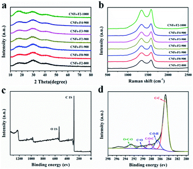 | ||
| Fig. 3 (a) XRD patterns and (b) Raman spectra of HPCNFs; (c) XPS survey spectra and (d) XPS of C1s region of the CNFs-F2-900. | ||
Raman spectra were performed to study the structures of the samples (Fig. 3b). The two prominent peaks around 1347 and 1580 cm−1 are identified as D and G bands of carbon materials, corresponding to the disordered and graphitic structures, respectively. The relative intensity of the D bands to the G bands (ID/IG), indicating the disordered degree of carbon materials,37–39 is calculated to be about 0.96, 0.97, 0.97, 0.97, 0.97, 0.97 and 0.98 for CNFs-F2-800, CNFs-F0-900, CNFs-F1-900, CNFs-F2-900, CNFs-F3-900, CNFs-F4-900 and CNFs-F2-1000, respectively. The results show that the amount of F127 and carbonation temperature have no significant effect on degree of graphitization. The results of Raman are in agreement with that of the XRD.
The surface compositions of the CNFs-F2-800, CNFs-F2-900 and CNFs-F2-1000 were studied by using the X-ray photoelectron spectrum (XPS). Fig. 3c shows that the CNFs-F2-900 is composed of C and O, peaking at the binding energies of them are around 285.0 eV and 532.0 eV. In Fig. 3d the C1s peak of CNFs-F2-900 exists in the form of C–C, C–O–H, C–O–C, C![[double bond, length as m-dash]](https://www.rsc.org/images/entities/char_e001.gif) O and O
O and O![[double bond, length as m-dash]](https://www.rsc.org/images/entities/char_e001.gif) C–O.40,41 The elemental composition of the CNFs-F2-800 and CNFs-F2-1000 is the same as that of CNFs-F2-900 as described in Fig. S4a–d,† but the element contents of the three samples are different (Table S1†). The O contents of the CNFs-F2-800, CNFs-F2-900 and CNFs-F2-1000 are respectively 12.70%, 10.33% and 5.40% because increasing the carbonization temperature leads to a rapid decrease in O contents. Therefore, these oxygen-enriched functionalities11 can both enhance wettability and produce pseudo capacitance to improve capacitance performance.
C–O.40,41 The elemental composition of the CNFs-F2-800 and CNFs-F2-1000 is the same as that of CNFs-F2-900 as described in Fig. S4a–d,† but the element contents of the three samples are different (Table S1†). The O contents of the CNFs-F2-800, CNFs-F2-900 and CNFs-F2-1000 are respectively 12.70%, 10.33% and 5.40% because increasing the carbonization temperature leads to a rapid decrease in O contents. Therefore, these oxygen-enriched functionalities11 can both enhance wettability and produce pseudo capacitance to improve capacitance performance.
To make sure that the influence of F127 pore-forming agent dosage on the pore structures of the samples CNFs-F0-900, CNFs-F1-900, CNFs-F2-900, CNFs-F3-900 and CNFs-F4-900, N2 adsorption–desorption isotherms were studied to measure the specific surface area and the porous distribution of the samples, and all the parameters are summarized shown in Fig. 4 and Table 1, respectively. As depicted in Fig. 4a, the samples exhibit steep uptakes typical type-IV curves at relative pressure (P/P0) = 0.1 and an H4-type hysteresis loop in the relative pressure range of 0.4–0.6, indicating the formation of abundant micropores and mesopores, respectively. Pore-size-distribution curves show that the size of the majority of the mesopores fall between 2.5 and 4.0 nm (Fig. 4b), corresponding to the hydrophobic chain (F127) length,42,43 which play an important role in fast an ion transfer.3 Furthermore, the minimum size of micropores in CNFs-F0-900, CNFs-F1-900, CNFs-F2-900, CNFs-F3-900 and CNFs-F4-900 are around 0.521, 0.511, 0.59, 0.56 and 0.61 nm, respectively, which are close to the size of hydrolyzed K+ ions (0.331 nm),44 implying that the micropores exhibited in all samples are beneficial to their capacitive performance. From Table 1 the surface areas, mesopore surface areas, total pore volumes and mesopore volume of CNFs-F2-900 and CNFs-F1-900 gradually get larger than that of CNFs-F0-900. The micropore surface areas and micropore volumes of them are not very different. This could be attributed to sacrificial template F127 removed to create more mesopores with increasing F127 pore-forming agent dosage and most of micropores from little potassium salt and decomposition of PVA and coal. But when the F127 mass increases to 0.6 g and 0.8 g, more F127 micelles form hydrogen bonds with hydroxyl groups of PVA, resulting in F127 dispersed inhomogeneous in solution, as the parameter shown in the Fig. 4 and Table 1 for CNFs-F3-900 and CNFs-F4-900. More F127 is used to produce more mesoporous so that mesopore surface areas gradually increase. While more micropores were destroyed, so micropore surface areas are reduced. The effect of carbonization temperatures on the specific surface and porous structure of the samples HPCNFs are also investigated (Fig. S5†). And Table S2† displays that the mesopore surface areas and mesopore volume of CNFs-F2-800, CNFs-F2-900 are not significantly different. The micropore surface areas and micropore volumes of CNFs-F2-900 at 900 °C are larger than that of CNFs-F2-800 at 800 °C and CNFs-F2-1000 at 1000 °C, which is due to little potassium salt and small molecular gas released by the degradation of PVA and carbonization of coal during carbonization. It can be clearly noted that the specific surface area and reasonable pore size distribution determine the capacitance performance.
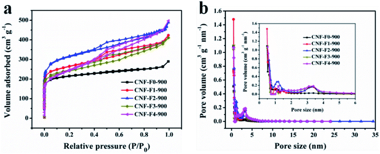 | ||
| Fig. 4 N2 adsorption–desorption isotherms (a) and pore size distributions (b) of CNFs-F0-900, CNFs-F1-900, CNFs-F2-900, CNFs-F3-900 and CNFs-F4-900 at the same temperature (900 °C). | ||
| Sample | SBETa (m2 g−1) | Smesob (m2 g−1) | Smicroc (m2 g−1) | Vtotald (cm3 g−1) | Vmesoe (cm3 g−1) | Vmicrof (cm3 g−1) | Dapg (nm) |
|---|---|---|---|---|---|---|---|
| a BET surface area.b Micropore surface area calculated using the V–t plot method.c Mesopore surface area calculated using the V–t plot method.d The total pore volume calculated by single point adsorption at P/P0 = 0.99.e The mesopore volume calculated using the V–t plot method.f The micropore volume calculated using the V–t plot method.g Average pore size. | |||||||
| CNFs-F0-900 | 821 | 123 | 698 | 0.44 | 0.14 | 0.30 | 2.5 |
| CNFs-F1-900 | 992 | 289 | 703 | 0.63 | 0.34 | 0.29 | 2.6 |
| CNFs-F2-900 | 1161 | 428 | 733 | 0.76 | 0.45 | 0.31 | 2.7 |
| CNFs-F3-900 | 891 | 502 | 389 | 0.72 | 0.48 | 0.24 | 3.2 |
| CNFs-F4-900 | 806 | 571 | 235 | 0.70 | 0.60 | 0.10 | 3.7 |
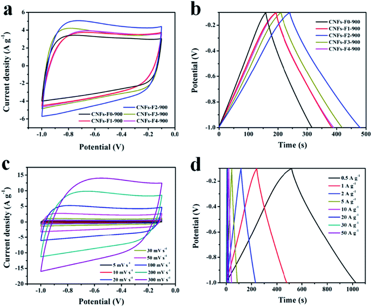
As described in Fig. 5a, the EDLCs behavior of electrode materials is nearly rectangular shape between −1 V and −0.1 V. The cyclic voltammograms (CV) curve of CNFs-F2-900 encircles the largest curve area in all the samples CNFs-F0-900, CNFs-F1-900, CNFs-F2-900, CNFs-F3-900 and CNFs-F4-900 at 100 mV s−1, suggesting a higher specific capacitance. Meanwhile, the galvanostatic charge–discharge curves of these samples at the same scan rate of 1 A g−1 are showed in Fig. 5b, the specific capacitance of CNFs-F2-900 is higher than those of others, because the CNFs-F2-900 has more mesopores than the samples CNFs-F0-900 and CNFs-F1-900 that provide pathways for electrolyte transport. Compared to CNFs-F3-900 and CNFs-F4-900, larger micropore surface areas of CNFs-F2-900 supply more active sites to electrosorption. The CV curves of CNFs-F2-900 (Fig. 5c) at different scan rates always retains their quasi-rectangular shape from −1 to −0.1 V, presenting the EDLCs characteristics in the charge–discharge process. Furthermore, the CV curve of CNFs-F2-900 still could retain a stable rectangular shape at a high scan rate up to 300 mV s−1, exhibiting a good rate capability of electrode materials. Fig. 5d shows that the galvanostatic charge–discharge curves of the CNFs-F2-900 at from 0.5 to 50.0 A g−1. All the charge–discharge curves are nearly linear and symmetrical, confirming its capacitor-like feature and good electrochemical reversibility, which result from rapid diffusion of electrolyte ions in electrode materials.8 The specific capacitance of CNFs-F2-900 is much larger than that of CNFs-F2-800 and CNFs-F2-1000 (Fig. S6†), indicating that superior porosity resulting from the pore-making agent (F127) and the proper carbonization.
The specific capacitance for CNFs-F2-900 (Fig. 6a) at various current density is calculated from the discharge curves. As shown in Fig. 6a, the specific capacitance of CNFs-F2-900 is as high as 282.1, 265.2, 253.1, 238.2, 226.3, 220.3, 214.4 and 193.6 F g−1 at 0.5, 1.0, 2.0, 5.0, 10.0, 20.0 30.0, and 50.0 A g−1, respectively. The results suggest that about 73.0% of the capacitance is retained with increasing of the charge–discharge rate from 1.0 to 50.0 A g−1. By comparison, the specific capacity of the CNFs-F2-900 is the highest in all electrode materials, which are ascribed to the larger accessible specific surface area, desirable pore size distribution and more available mesoporous channels as described above.
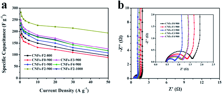 | ||
| Fig. 6 (a) Specific capacitances of all samples at the current density of 0.5–50.0 A g−1; (b) electrochemical impedance spectra of HPCNFs as Nyquist plots. | ||
The electrochemical impedance spectra (EIS) of the all the samples were measured to compare the ion-transport behavior and electrical resistance (Fig. 6b). The results show that all the electrodes are nearly perpendicular to the imaginary axis in the low frequency region, presenting an ideally capacitive behavior of the samples and the diffusion and migration of the electrolyte ions within the electrode structure. In the high frequency region, it could be clearly found that the first intersection point in real axis is solution resistance (Rs),45 which is 0.477, 0.484, 0.485, 0.483 and 0.490 Ω for CNFs-F0-900, CNFs-F1-900, CNFs-F2-900, CNFs-F3-900 and CNFs-F4-900, respectively. Moreover, the diameter of a semicircle is a characteristic of charge transfer resistance (Rct), and the resistance to electrolyte transport for CNFs-F2-900 is observed to be smallest in all the samples, due to the more available mesoporous channels. Hence, hierarchical porous structure of the CNFs-F2-900 is beneficial for charge transfer and ion diffusion.
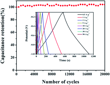
The response and better rating of the capacitor have further been proved its long-term cyclic stability. The cycling capacitance performance of the CNFs-F2-900 was researched by galvanostatic charge–discharge cycling at 10.0 A g−1 for 20![[thin space (1/6-em)]](https://www.rsc.org/images/entities/char_2009.gif) 000 cycles (Fig. 7). As shown in the inset image in Fig. 7, after alternating charge–discharge process, the specific capacitance for CNFs-F2-900 still reaches 231.3 F g−1 at 10.0 A g−1. It is observed that CNFs-F2-900 retains about 105% of their initial capacitance after 20
000 cycles (Fig. 7). As shown in the inset image in Fig. 7, after alternating charge–discharge process, the specific capacitance for CNFs-F2-900 still reaches 231.3 F g−1 at 10.0 A g−1. It is observed that CNFs-F2-900 retains about 105% of their initial capacitance after 20![[thin space (1/6-em)]](https://www.rsc.org/images/entities/char_2009.gif) 000 charge/discharge cycles, indicating that excellent electrochemical stability of the CNFs-F2-900. Furthermore, the SEM image in Fig. S7† shows the CNFs-F2-900 electrode can keep its original morphology after 20
000 charge/discharge cycles, indicating that excellent electrochemical stability of the CNFs-F2-900. Furthermore, the SEM image in Fig. S7† shows the CNFs-F2-900 electrode can keep its original morphology after 20![[thin space (1/6-em)]](https://www.rsc.org/images/entities/char_2009.gif) 000 cycles of durability testing, demonstrating the electrode material possesses a good stability. The specific capacitance and cycling stability of our materials were compared with previous carbonaceous works of CNFs and the data are listed in Table S3.† Furthermore, the two-electrode cell was measured in 6 M KOH. Fig. S8a† shows the CV curves of the CNFs-F2-900 at from 10 to 100 mV s−1, and its galvanostatic charge–discharge curves at various current densities (Fig. S8b†). We found that CNFs-F2-900 has a specific capacitance of 87 F g−1 at 1 A g−1. The capacitance retention percentage at 30 A g−1 relative to that at 1 A g−1 is 65.5%.
000 cycles of durability testing, demonstrating the electrode material possesses a good stability. The specific capacitance and cycling stability of our materials were compared with previous carbonaceous works of CNFs and the data are listed in Table S3.† Furthermore, the two-electrode cell was measured in 6 M KOH. Fig. S8a† shows the CV curves of the CNFs-F2-900 at from 10 to 100 mV s−1, and its galvanostatic charge–discharge curves at various current densities (Fig. S8b†). We found that CNFs-F2-900 has a specific capacitance of 87 F g−1 at 1 A g−1. The capacitance retention percentage at 30 A g−1 relative to that at 1 A g−1 is 65.5%.
With regard to the above good electrochemical properties of CNFs-F2-900, there are three reasons as followed. Firstly, large effective specific surface provides more electroactive sites for ion accumulation and energy storage. Secondly, ion diffusion length is further shortened, since the hierarchical porous structure in one-dimensional CNFs can effectively decrease the ion transport channel. Thirdly, the empty spaces in HPCNFs accommodate the volume changes connected with electrochemical reactions, so the stable structure makes the electrode material with an excellent cycle stability.
4. Conclusion
In summary, we have designed a green method to prepare coal based HPCNFs. When the mass of F127 is 0.4 g and the carbonization temperature is 900 °C, the CNFs-F2-900 exhibits excellent electrochemical performance as supercapacitor electrodes, in particular attaining high specific capacitance at different current densities (265.2 F g−1 at 1.0 A g−1 and 220.3 F g−1 at 20.0 A g−1) and outstanding cycling stability without any decrease in the specific capacitance after 20![[thin space (1/6-em)]](https://www.rsc.org/images/entities/char_2009.gif) 000 cycles. Therefore, this work paves a desired route to produce HPCNFs.
000 cycles. Therefore, this work paves a desired route to produce HPCNFs.
Conflicts of interest
There are no conflicts to declare.Acknowledgements
This work is supported by the National Natural Science Foundation of China (U1703251 and 21571152), the Open Fund of the Key Laboratory of Xinjiang Uygur Autonomous Region (2017D04014), Scientific Research Program of the Higher Education Institution of Xinjiang (XJEDU2017A001) and the Doctoral Innovation Program of Xinjiang University (XJUBSCX-2017011).References
- F. Liu, M. H. Jang, H. D. Ha, J. H. Kim, Y. H. Cho and T. S. Seo, Facile synthetic method for pristine graphene quantum dots and graphene oxide quantum dots: origin of blue and green luminescence, Adv. Mater., 2013, 25, 3657–3662 CrossRef CAS PubMed.
- S. Wang, I. S. Cole, D. Zhao and Q. Li, The dual roles of functional groups in the photoluminescence of graphene quantum dots, Nanoscale, 2016, 8, 7449–7458 RSC.
- W. Zhang, H. Lin, Z. Lin, J. Yin, H. Lu, D. Liu and M. Zhao, 3D Hierarchical Porous Carbon for Supercapacitors Prepared from Lignin through a Facile Template-Free Method, ChemSusChem, 2015, 8, 2114–2122 CrossRef CAS PubMed.
- Z. N. Yu, L. Tetard, L. Zhai and J. Thomas, Supercapacitor electrode materials: nanostructures from 0 to 3 dimensions, Energy Environ. Sci., 2015, 8, 702–730 RSC.
- G. P. Wang, L. Zhang and J. J. Zhang, A review of electrode materials for electrochemical supercapacitors, Chem. Soc. Rev., 2012, 41, 797–828 RSC.
- A. G. Pandolfo and A. F. Hollenkamp, Carbon properties and their role in supercapacitors, J. Power Sources, 2006, 157, 11–27 CrossRef CAS.
- N. Bhattarai, Z. S. Li, D. Edmondson and M. Q. Zhang, Alginate-based nanofibrous scaffolds: structural, mechanical, and biological properties, Adv. Mater., 2006, 18, 1463–1467 CrossRef CAS.
- W. Liu, Y. K. Tang, Z. P. Sun, S. S. Gao, J. H. Ma and L. Liu, A simple approach of constructing sulfur-containing porous carbon nanotubes for high-performance supercapacitors, Carbon, 2017, 115, 754–762 CrossRef CAS.
- P. Hao, Z. H. Zhao, J. Tian, H. D. Li, Y. H. Sang, G. W. Yu, H. Q. Cai, H. Liu, C. P. Wong and A. Umar, Hierarchical porous carbon aerogel derived from bagasse for high performance supercapacitor electrode, Nanoscale, 2014, 6, 12120–12129 RSC.
- L. R. Kong, Q. R. Chen, X. P. Shen, C. Xia, Z. Y. Jia and J. Zhu, Ionic Liquid Templated Porous Boron-Doped Graphitic Carbon Nitride Nanosheet Electrode for High-Performance Supercapacitor, Electrochim. Acta, 2017, 245, 249–258 CrossRef CAS.
- B. Zhang, F. Y. Kang, J. M. Tarascon and J. K. Kim, Recent advances in electrospun carbon nanofibers and their application in electrochemical energy storage, Prog. Mater. Sci., 2016, 76, 319–380 CrossRef CAS.
- W. Li, F. Zhang, Y. Q. Dou, Z. X. Wu, H. J. Liu, X. F. Qian, D. Gu, Y. Y. Xia, B. Tu and D. Y. Zhao, A Self-Template Strategy for the Synthesis of Mesoporous Carbon Nanofibers as Advanced Supercapacitor Electrodes, Adv. Energy Mater., 2011, 1, 382–386 CrossRef CAS.
- H. Y. Zhao, L. X. Wang, D. Z. Jia, W. Xia, J. Li and Z. P. Guo, Coal based activated carbon nanofibers prepared by electrospinning, J. Mater. Chem. A, 2014, 2, 9338–9344 RSC.
- Y. T. He, L. X. Wang and D. Z. Jia, Coal/PAN interconnected carbon nanofibers with excellent energy storage performance and electrical conductivity, Electrochim. Acta, 2016, 194, 239–245 CrossRef CAS.
- X. L. Song, J. X. Guo, M. X. Guo, D. Z. Jia, Z. P. Sun and L. X. Wang, Freestanding needle-like polyaniline–coal based carbon nanofiber composite flexible paper for supercapacitor, Electrochim. Acta, 2016, 206, 337–345 CrossRef CAS.
- M. Yang, S. Ko, J. S. Im and B. G. Choi, Free-standing molybdenum disulfide/graphene composite paper as a binder- and carbon-free anode for lithium-ion batteries, J. Power Sources, 2015, 288, 76–81 CrossRef CAS.
- X.-Q. Zhang, Q. Sun, W. Dong, D. Li, A.-H. Lu, J.-Q. Mu and W.-C. Li, Synthesis of superior carbon nanofibers with large aspect ratio and tunable porosity for electrochemical energy storage, J. Mater. Chem. A, 2013, 1, 9449–9455 RSC.
- R. L. Liu, L. X. Pan, L. Wan and D. Q. Wu, An evaporation-induced tri-consistent assembly route towards nitrogen-doped carbon microfibers with ordered mesopores for high performance supercapacitors, Phys. Chem. Chem. Phys., 2015, 17, 4724–4729 RSC.
- Y. L. Cheng, L. Huang, X. Xiao, B. Yao, Z. M. Hu, T. Q. Li, K. Liu and J. Zhou, Cross-linked carbon network with hierarchical porous structure for high performance solid-state electrochemical capacitor, J. Power Sources, 2016, 327, 488–494 CrossRef CAS.
- K.-H. Jung and J. P Ferraris, Preparation of porous carbon nanofibers derived from PBI/PLLA for supercapacitor electrodes, Nanotechnology, 2016, 27, 425708 CrossRef PubMed.
- Y. Lu, K. Fu, S. Zhang, Y. Li, C. Chen, J. D. Zhu, M. Yanilmaz, M. Dirican and X. W. Zhang, Centrifugal spinning: a novel approach to fabricate porous carbon fibers as binder-free electrodes for electric double-layer capacitors, J. Power Sources, 2015, 273, 502–510 CrossRef CAS.
- L. F. Chen, Y. Lu, L. Yu and X. W. Lou, Designed formation of hollow particle-based nitrogen-doped carbon nanofibers for high-performance supercapacitors, Energy Environ. Sci., 2017, 10, 1777–1783 RSC.
- Y. M. Sun, R. B. Sills, X. L. Hu, Z. W. She, X. Xiao, H. H. Xu, W. Luo, H. Y. Jin, Y. Xin, T. Q. Li, Z. L. Zhang, J. Zhou, W. Cai, Y. H. Huang and Y. Cui, A Bamboo-Inspired Nanostructure Design for Flexible, Foldable, and Twistable Energy Storage Devices, Nano Lett., 2015, 15, 3899–3906 CrossRef CAS.
- L. J. Zhang, Y. Z. Jiang, L. W. Wang, C. Zhang and S. X. Liu, Hierarchical porous carbon nanofibers as binder-free electrode for high-performance supercapacitor, Electrochim. Acta, 2016, 196, 189–196 CrossRef CAS.
- D. Lee, J. Y. Jung, M. J. Jung and Y. S. Lee, Hierarchical porous carbon fibers prepared using a SiO2 template for high-performance EDLCs, Chem. Eng. J., 2015, 263, 62–70 CrossRef CAS.
- C. Kim, B. T. Ngoc, K. S. Yang, M. Kojima, Y. Kim, Y. J. Kim, M. Endo and S. C. Yang, Self-sustained thin webs consisting of porous carbon nanofibers for supercapacitors via the electrospinning of polyacrylonitrile solutions containing zinc chloride, Adv. Mater., 2007, 19, 2341–2346 CrossRef CAS.
- H. Liu, C.-Y. Cao, F.-F. Wei, Y. Jiang, Y.-B. Sun, P.-P. Huang and W.-G. Song, Fabrication of Macroporous/Mesoporous Carbon Nanofiber Using CaCO3 Nanoparticles as Dual Purpose Template and Its Application as Catalyst Support, J. Phys. Chem. C, 2013, 117, 21426–21432 CrossRef CAS.
- H. Q. Wang, C. P. Zhang, Z. X. Chen, H. K. Liu and Z. P. Guo, Large-scale synthesis of ordered mesoporous carbon fiber and its application as cathode material for lithium–sulfur batteries, Carbon, 2015, 81, 782–787 CrossRef CAS.
- S. Q. Xiong, J. C. Fan, Y. Wang, J. Zhu, J. R. Yua and Z. M. Hua, A facile template approach to nitrogen-doped hierarchical porous carbon nanospheres from polydopamine for high-performance supercapacitors, J. Mater. Chem. A, 2017, 15, 18242–18252 RSC.
- G. Xin, Y. Wang, S. Jia, P. Tian, S. Zhou and J. Zang, Synthesis of nitrogen-doped mesoporous carbon from polyaniline with an F127 template for high-performance supercapacitors, Appl. Surf. Sci., 2017, 422, 654–660 CrossRef CAS.
- M. X. Guo, J. X. Guo, D. Z. Jia, H. Y. Zhao, Z. P. Sun, X. L. Song and Y. H. Li, Coal derived porous carbon fibers with tunable internal channels for flexible electrodes and organic matter absorption, J. Mater. Chem. A, 2015, 3, 21178–21184 RSC.
- S. Q. Xiong, J. C. Fan, Y. Wang, J. Zhu, J. R. Yua and Z. M. Hua, facile template approach to nitrogen-doped hierarchical porous carbon nanospheres from polydopamine for high-performance supercapacitors, J. Mater. Chem. A, 2017, 5, 18242–18252 RSC.
- D. Hulicova-Jurcakova, X. Li, Z. H. Zhu, R. D. Marco and G. Q. Lu, Graphitic Carbon Nanofibers Synthesized by the Chemical Vapor Deposition (CVD) Method and Their Electrochemical Performances in Supercapacitors, Energy Fuels, 2008, 22, 4139–4145 CrossRef CAS.
- M. A. Kabbani, V. Kochat, S. Bhowmick, M. Soto, A. Som, K. R. Krishnadas, C. F. Woellner, Y. M. Jaques, E. V. Barrera, S. Asif, R. Vajtai and T. Pradeep, Consolidation of functionalized graphene at ambient temperature via mechano-chemistry, Carbon, 2018, 134, 491–499 CrossRef CAS.
- S. Lee, J. Kim, B.-C. Ku, J. Kim and H.-I. Joh, Structural Evolution of Polyacrylonitrile Fibers in Stabilization and Carbonization, Adv. Chem. Eng. Sci., 2012, 2, 275–282 CrossRef CAS.
- T. H. Hwang, D. S. Jung, J.-S. Kim, B. G. Kim and J. W. Choi, One-dimensional carbon-sulfur composite fibers for Na-S rechargeable batteries operating at room temperature, Nano Lett., 2013, 13, 4532–4538 CrossRef CAS PubMed.
- M. Liu, X. Ma, L. Gan, Z. Xu, D. Zhu and L. Chen, A facile synthesis of a novel mesoporous Ge@C sphere anode with stable and high capacity for lithium ion batteries, J. Mater. Chem. A, 2014, 2, 17107–17114 RSC.
- X. Liu, S. Zou and S. Chen, Ordered mesoporous carbons codoped with nitrogen and iron as effective catalysts for oxygen reduction reaction, Nanoscale, 2016, 8, 9249–19255 Search PubMed.
- A. C. Ferrari and J. Robertson, Interpretation of Raman spectra of disordered and amorphous carbon, Phys. Rev. B: Condens. Matter Mater. Phys., 2000, 61, 14095 CrossRef CAS.
- B. Liu, Y. J. Liu, H. B. Chen, M. Yang and H. M. Li, Oxygen and nitrogen co-doped porous carbon nanosheets derived from Perilla frutescens for high volumetric performance supercapacitors, J. Power Sources, 2017, 341, 309–317 CrossRef CAS.
- C. G. Tang, Y. J. Liu, D. G. Yang and M. L. Yang, Oxygen and nitrogen co-doped porous carbons with finely-layered schistose structure for high-rate-performance supercapacitors, Carbon, 2017, 221, 538–546 CrossRef.
- L. Borchardt, M. Oschatza and S. Kaskel, Tailoring porosity in carbon materials for supercapacitor applications, Mater. Horiz., 2014, 1, 157–168 RSC.
- C. H. Kim and B.-H. Kim, Effects of thermal treatment on the structural and capacitive properties of polyphenylsilane-derived porous carbon nanofibers, Electrochim. Acta, 2014, 117, 26–33 CrossRef CAS.
- C. J. Raj, M. Rajesh, R. Manikandan, K. H. Yu, J. R. Anusha, J. H. Ahn, D.-W. Kim, S. Y. Parke and B. C. Kim, High electrochemical capacitor performance of oxygen and nitrogen enriched activated carbon derived from the pyrolysis and activation of squid gladius chitin, J. Power Sources, 2018, 386, 66–76 CrossRef CAS.
- S. Vijayakumar, S. Nagamuthu and G. Muralidharan, Porous NiO/C nanocomposites as electrode material for electrochemical supercapacitors, ACS Sustainable Chem. Eng., 2013, 1, 1110–1118 CrossRef CAS.
Footnote |
| † Electronic supplementary information (ESI) available: TG curves of oxidized coal, PVA, F127 and precursor CNFs-F4-900, respectively. SEM, TEM and HRTEM images of HPCNFs at 800 °C and 1000 °C. XRD patterns of oxidized coal. XPS survey spectra and XPS elemental analysis of HPCNFs at 800 °C and 1000 °C. N2 adsorption–desorption isotherms and pore size distributions and BET specific surface areas and porous structure of HPCNFs at different temperature. CV curves and galvanostatic charge–discharge curves of the samples at different temperature. SEM characterizations of the CNFs-F2-900 electrode after discharge/charge cycles. Maximum capacitances and cycling stability of porous carbon nanofiber materials. CV curves and CP cures of the sample CNFs-F2-900 as symmetrical electrode. See DOI: 10.1039/c8ra08949c |
| This journal is © The Royal Society of Chemistry 2019 |

