 Open Access Article
Surface modification and direct plasma amination of L605 CoCr alloys: on the optimization of the oxide layer for application in cardiovascular implants
Sergio Diaz-Rodrigueza,
Pascale Chevalliera,
Carlo Paternostera,
Vanessa Montaño-Machadoa,
Céline Noëlb,
Laurent Houssiaub and
Diego Mantovani *a
*a
aLaboratory for Biomaterials and Bioengineering (CRC-I), Department of Min-Met-Mat Engineering and the CHU de Québec Research Center, Laval University, PLT-1745G, Québec, Québec G1V 0A6, Canada. E-mail: diego.mantovani@gmn.ulaval.ca; Tel: +1 (418) 656-2131 ext 6270
bLaboratoire Interdisciplinaire de Spectroscopie Electronique, Namur Institute of Structured Matter, University of Namur, 61 Rue de Bruxelles, 5000 Namur, Belgium
First published on 17th January 2019
Abstract
Stents are cardiovascular devices used to treat atherosclerosis, and are deployed into narrowed arteries and implanted by expansion to reopen the biological lumen. Nevertheless, complications after implantation are still observed in 10–14% of the implantations. Therefore, functionalizing these devices with active molecules to improve the interfacial effects with the surrounding tissue strongly impacts their success. A plasma-based procedure to directly graft biomolecules to the surface of cobalt chromium alloys, without any polymeric coating, has been recently reported. Assuring the stability of the coating during plastic deformation generated during the implantation whilst avoiding the corrosion of the surface is crucial. This study explores different surface treatments to be used as a pre-treatment for this novel procedure. The effects of (i) electropolishing, (ii) thermal treatments, and (iii) the plasma immersion ion implantation of oxygen on the chemical composition, roughness, wettability and efficiency during the plasma-amination procedure whilst avoiding cracks after deformation, thus maintaining corrosion resistant behaviour, were investigated by XPS, AFM, ToF-SIMS imaging and depth profile, and WCA. Furthermore, the hemocompatibility of the surface and cell viability assays were also performed. Results showed that all of the treatments created a different surface chemical composition: EP mainly of chromium oxide, PIII with a layer of cobalt oxide and TT with a mixture of oxides, as observed by XPS and ToF-SIMS. Moreover, EP was the process that generated a surface with the highest efficiency to amination and the most corrosion resistance among the treatments, and it appeared as the most suitable pre-treatment for stent functionalization.
1 Introduction
Atherosclerosis is a cardiovascular disease characterized by the formation of a plaque that narrows the arterial walls, leading to thrombus formation and ultimately heart attacks.1 Once it has progressed to the late stages, this disease is surgically treated by the implantation of a stent which is a metallic wire mesh. This device is introduced with a catheter to the narrowed zone and is expanded up to 25% deformation to reopen the arterial flow, deploying the device whilst avoiding the collapse of the artery.2,3 Among the materials used for bare metal stents (BMS), there is cobalt chromium L605 alloy, which has interesting mechanical properties and is covered with a passive oxide layer that protects the surface from potential corrosion. Furthermore, this alloy allows for the fabrication of thinner devices with smaller struts that have been correlated to lower clinical post-implantation adverse effects.4 Nevertheless, complications with BMS remain, for example in-stent restenosis, thrombus formation, and endothelium damage still occur due to the invasive procedures of stent deployment.5 Although, drug eluting stents (DES) have been developed to counter these complications by releasing drugs from a polymeric coating (deposited on the surface). Nonetheless, cracks and delamination of this coating have been observed due to the lack of adhesion and cohesion between the surface and the coating.6,7 This finding can be related to the complex geometry of the stents and the deposition techniques of the polymeric layer (dip coating, spray coating, layer by layer coating, etc.) that can not assure coating stability during the deployment of the device.8Therefore, a novel procedure that allows for the direct covalent grafting of active molecules without any intermediate layer to enhance the biological performance of cardiovascular devices has been developed. Briefly, this procedure focuses on direct functionalization with primary amine groups (–NH2), known for their high reactivity,9 on the surface of the L605 alloys that act as anchor points for the further grafting of molecules of interest with free carboxylic groups in their structure (–COOH). Assuring the stability and the properties of the surface (oxide layer) thus appears crucial for the application of this strategy for cardiovascular devices. This oxide layer must resist deformation related to the deployment of the device, and must be corrosion resistant to avoid the release of toxic ions in the blood stream, whilst being biocompatible.6,10,11 Among the different strategies to modify the oxide layers and the finishing of metallic substrates, procedures can be divided into mechanical treatments, thermal treatments, ion implantation and chemical treatments.12 All of these treatments can modulate properties such as chemical composition, surface roughness, corrosion and deformation resistance, wettability, blood compatibility and cytotoxicity.
Although all of these treatments can modify the surface of metallic substrates, regarding the stent applications mechanical treatments (mechanical polishing for example) are not suitable due to the complex geometry of the devices. Therefore, thermal treatments, ion implantation and chemical treatments represent suitable modification procedures. For instance, thermal treatments in a controlled atmosphere can be used to achieve homogeneous changes in the chemical and structural composition.12,13 In regards to ion implantation processes, such as plasma immersion ion implantation (PIII), these can produce changes both on the surface and in the internal structure, producing an amorphous oxide layer, due to the acceleration of ions into the metallic substrate.11,14–16 Finally, chemical treatments, for example electropolishing, allow for the removal of any surface contaminant and the passivation of the surface whilst obtaining a nano-smooth surface with a mirror like finish.7,12,17
This study focuses on the surface preparation step of L605 alloys for their direct plasma amination. Three different surface treatments on L605 CoCr alloys to modify the oxide layer are proposed: electropolishing (EP), as a base treatment, followed by either thermal treatment (TT) or the PIII of oxygen. The specimens were thoroughly characterized by X-ray Photoelectron Spectroscopy (XPS), Time of Flight-Secondary Ion Mass Spectrometry (ToF-SIMS), Atomic Force Microscopy (AFM), Scanning Electron Microscopy (SEM) and Water Contact Angle (WCA) to study their chemical composition, topography and wettability. Furthermore, the influence of these properties on the plasma amination efficiency of the surface was assessed. The deformation resistance and the corrosion behaviour were also determined along with the biological performance of the surface (hemocompatibility and short-term cellular response). These biological properties were selected to study the potential effect of the device on wound healing of the endothelium and thrombus formation.
2 Materials and methods
2.1 Materials
L605 alloy sheets (nominal composition wt%: Co 51%, Cr 20%, W 15%, Ni 10%, Fe ≤ 3%) were purchased from Rolled Alloys Inc. (QC, Canada). Acetone and methanol (ACS grade, respectively) were purchased from Fisher Scientific (NJ, USA). Phosphoric acid (85%), sulfuric acid (ACS grade), and hydrofluoric acid (48%) were purchased from Laboratoire MAT (QC, Canada). From Sigma-Aldrich, the following reagents were purchased: sodium hydroxide (≥97%, pellets), calcium chloride (99.99%) and 5-bromosalicyladehyde (98%). PBS (phosphate buffered solution, 1× powder) was purchased from Fisher Scientific.2.2 Sample preparation
2.3 Stability tests
 | (1) |
2.4 Plasma functionalization
2.5 Biological tests
![[thin space (1/6-em)]](https://www.rsc.org/images/entities/char_2009.gif) 000 cells in M199 (Thermo Fisher, 11150-067) culture media containing serum and penicillin-streptomycin (Gibco, 15140-122) were deposited on surfaces and incubated at 37 °C. After adhesion for 24 h, cells were rinsed with PBS in order to eliminate all remaining culture medium. 300 μL of solution of resazurin in the culture medium (1
000 cells in M199 (Thermo Fisher, 11150-067) culture media containing serum and penicillin-streptomycin (Gibco, 15140-122) were deposited on surfaces and incubated at 37 °C. After adhesion for 24 h, cells were rinsed with PBS in order to eliminate all remaining culture medium. 300 μL of solution of resazurin in the culture medium (1![[thin space (1/6-em)]](https://www.rsc.org/images/entities/char_2009.gif) :
:![[thin space (1/6-em)]](https://www.rsc.org/images/entities/char_2009.gif) 10) were then added to the samples and allowed to react for 4 h. 150 μL were taken from each sample and the fluorescence was measured at 570 nm using a spectrophotometer ELISA reader (BioRad mod.450, ON, Canada).
10) were then added to the samples and allowed to react for 4 h. 150 μL were taken from each sample and the fluorescence was measured at 570 nm using a spectrophotometer ELISA reader (BioRad mod.450, ON, Canada).2.6 Surface characterization
During ToF-SIMS depth profiling, the analysis beam (as previously described) and the erosion beam (Cs+ at 500 eV, current: 40–45 nA), rastered over a 500 × 500 μm2 area to avoid border effects, were operated in non-interlaced mode with one analysis frame (1.6384 s) and 5 s erosion per cycle, both with a 45° incidence angle to the sample surface.
3 Results
3.1 Selection of conditions
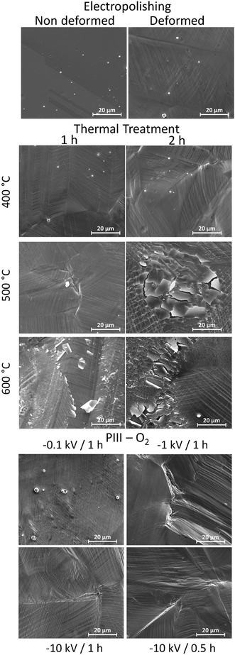
Due to the importance of the mechanical stability of the oxide layer during the deployment of a stent, a deformation test was performed in order to evaluate the resistance of the different treatments. As observed in Fig. 1, conditions such as 600 °C for 1 h for TT and in the case of PIII, −10 kV for 1 h, presented cracks and peelings on their oxide layer. Therefore, such conditions were discarded. From the remaining conditions, only one for each treatment was selected for the complete study. The selected conditions were EP as a base treatment, TT at 400 °C for 1 h and PIII −0.1 kV for 1 h.3.2 Surface treatments
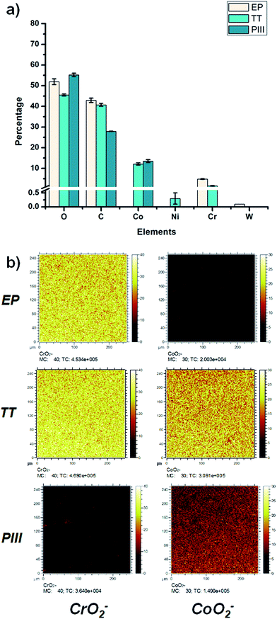
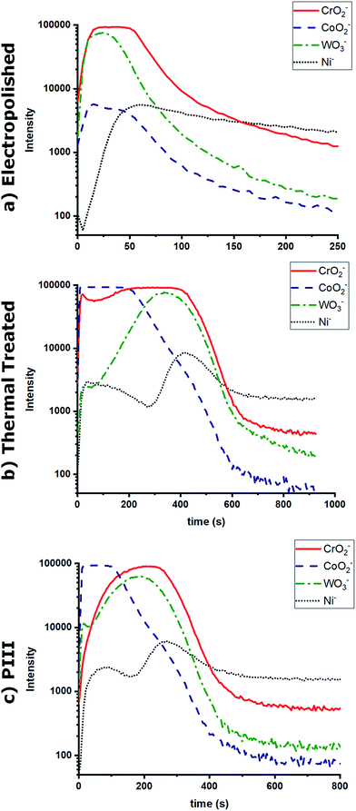
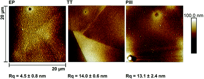
The chemical composition of the oxide layers, assessed by XPS survey analyses, shown in Fig. 2a, showed that the first few nanometers of the oxide layer of the EP sample surface were composed mainly of chromium (%Cr = 4.8 ± 0.2); on the contrary, the PIII sample surface was composed of cobalt (%Co = 13.5 ± 0.7%); finally, the TT sample surfaces showed the presence of both cobalt and chromium oxides (%Cr = 1.5 ± 0.2, %Co = 12.1 ± 0.5) with traces of other metals such as nickel. Moreover, the distribution of CrO2− and CoO2− ions was studied for each of the metallic oxides by ToF-SIMS imaging in negative mode (Fig. 2b). This confirmed what was observed in the XPS survey results, where it was found that the composition of the outmost layers of EP, TT and PIII follows the same trend. ToF-SIMS depth profile analyses were also performed to obtain information about the depth distribution of the different elements of the oxide layers. Fig. 3 shows the obtained profiles where it was found that the EP oxide was the thinnest of them all (∼50 s of sputtering) and is composed mainly of chromium oxide. PIII on the other side, has a thicker oxide layer that is composed of a topmost cobalt oxide layer on a chromium oxide sublayer (∼150 s and ∼350 s of sputtering, respectively). Finally, TT has a thick oxide layer composed of both cobalt and chromium oxides on the topmost layer of the surface (∼600 s of sputtering). It is worth noting that SRIM simulations have been performed to estimate the sputter yields of chromium and cobalt oxides under Cs bombardment and that their similar values (2.4 and 2.6 atoms per ion, respectively) allowed us to safely compare the sputter times between the profiles and equate them with depths.The morphology of the substrate surface was evaluated through AFM (Fig. 4). The presence of grain boundaries can be observed on the EP surface, but not as visibly as on the TT surface, whereas on PIII, grain boundaries are not clearly present. Regarding the surface roughness, Rq, it was found that the smoothest surface among the different treatments was EP and that after surface modification this value increased significantly on both TT and PIII.
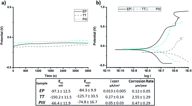
To investigate the corrosion behaviour of the different surface treatments, OCP and potentiodynamic polarization analyses were performed. Regarding OCP (Fig. 5a) it was found that TT, composed of a mixture of chromium and cobalt oxides, had the lowest open circuit potential, had the most reactive oxide layer and was the most susceptible to corrosion, compared to the other surfaces, whilst PIII was the one with the most positive potential and had the least reactive oxide layer. Potentiodynamic curves (Fig. 5b) allowed for the calculation of the corrosion rate where it was found that, as observed in the OCP curves, TT was the surface treatment with the highest corrosion rate, followed by PIII and finally EP with a ∼20× decrease compared to TT. These values and a summary of the results are shown in Fig. 5c.
3.3 Plasma functionalization
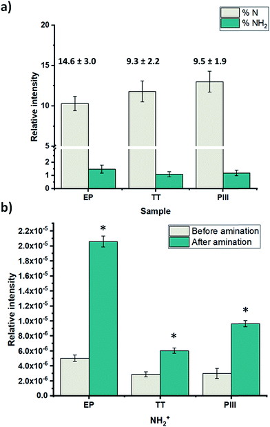
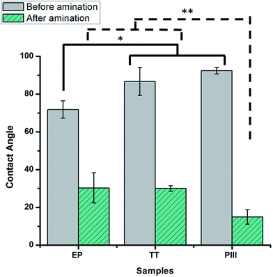
After the complete characterization of the different oxide surfaces, direct plasma amination was carried out. For the characterization of the surface, chemical derivatization was performed in order to confirm the presence of the amine groups.21 XPS survey analysis results show that on the TT and PIII surfaces there was a significantly higher percentage of nitrogen on the surface compared to EP, as shown in Fig. 6a. Moreover, there was a significant difference in the percentage of NH2 on EP compared with the other two surface treatments, but not between TT and PIII. Finally, the efficiency of the functionalization (%NH2/N) was assessed. This was calculated from the percentage of amine groups deduced from chemical derivatization (%NH2) and the percentage of nitrogen on the surface after plasma treatment. It was found that EP was the one with the highest efficiency, close to 15%, compared to the other surface treatments, around 9%, as observed in Fig. 6a.Due to the present debate for the use of chemical derivatization as a valid quantification method for primary amine groups, supplementary surface characterization was performed.24 Complementary results obtained from ToF-SIMS static mode analyses for the NH2+ fragment confirmed that EP has a higher relative concentration of this fragment, followed by PIII and then TT with the lowest signal, as observed in Fig. 6b. Another characterization technique that was performed was contact angle, where it was found that the wettability of all surface treatments changed from a relatively hydrophobic behaviour to a more hydrophilic surface after plasma amination, as observed in Fig. 7.
3.4 Biological performance
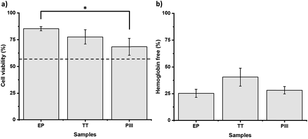
Further characterization of the surfaces was performed in order to evaluate the biological performance of the different conditions. The viability of HUVEC was studied after 24 h of contact with the samples. As observed in Fig. 8a, significantly higher cell viability was observed under the EP conditions (>80%) when compared to the PIII ones (>60%), while TT presented intermediate behaviour with no significant difference with TT nor with EP (>70%). Hence, EP exhibited the higher viability of all the samples. Regarding the evaluation of the hemocompatibility, neither of the samples presented thrombus formation after 20 min of contact with whole blood (Fig. 8b). The TT conditions seemed to present a higher amount of free hemoglobin and therefore the best hemocompatibility. However, no significant differences were found among the different conditions after statistical analysis, mainly because of the high variations observed.4 Discussion
The aim of this work was to study different surface treatments on L605 CoCr alloys with potential application for cardiovascular devices. In order to find the most suitable oxide layer, properties such as deformation and corrosion resistance, efficiency towards direct functionalization (therein amination) and biological performance in terms of cytotoxicity and hemocompatibility were studied.Therefore, one of the initial properties that was sought after for these oxide layers was the resistance to deformation, without showing either cracks or delamination. After deforming them up to 25%, similar to a stent deployment,18 some of the initially proposed conditions exhibited cracks and delamination, as observed in Fig. 1, meaning that their oxide layers were unstable and not suitable for application. This may be explained by the formation of brittle or too thick oxide layers that were not able to sustain deformation. Regarding the thermal treated samples, the only oxide layer to not exhibit cracks and delamination was the one obtained at 400 °C for 1 h (Fig. 1), despite being approximately 10 times thicker than the oxide layer obtained after EP, as observed by the ToF-SIMS depth-profile results (sputter time 600 s versus 60 s, respectively – Fig. 3). The failure of thermal treatments at higher temperatures and longer times could be related to the formation of bigger oxide crystals (as seen in Fig. 1 for 500 °C – 2 h, and 600 °C – 1 h and 2 h). Similar observations have already been described by Griffage et al. where they found that during thermal treatments the L605s surface had a low resistance to oxidation, resulting in a thicker oxide layer as a function of temperature and time.25 Moreover, the mechanism for cracks and delamination proposed by Wang et al. was considered, which involves the formation of microcracks/voids and a high density of oxide particles on the grain boundaries in the near-surface area that propagate parallel to the alloy surface with deformation.26 These features create a less ductile surface than the underlying bulk leading to peeling, cracks and delamination. This mechanism explains what was observed at the higher temperatures of the thermal treatments (Fig. 1), making these conditions not suitable for the desired application.
In the case of the PIII treatments, a higher bias voltage (−1 kV and −10 kV) appeared to induce a thicker oxide layer which was unstable to deformation, without formation of crystals compared to TT, as observed in Fig. 1, whereas the oxide surface obtained at the lowest bias, −0.1 kV, sustained the deformation. It is known that oxygen implantation doses can modulate the crystalline structure (hexagonal Co-oxygen rich phase), and the oxide layer thickness, thus leading to changes in the mechanical properties (hardness).27,28 The ion doses are higher when the bias voltage applied on the sample is more negative, leading to the acceleration of positive ions which are thus more implanted (an increase of the oxide thickness). Thus, −1 kV and −10 kV should create a thicker oxide layer than the one obtained at −0.1 kV, which already needed a sputter time of 400 s (Fig. 3, ToF-SIMS depth profile). Moreover, as can be observed in Fig. 1, the failure of the PIIIs oxide layer is mainly due to delamination rather than to the formation of cracks, as seen in the thermal treatments. This behaviour might be related to the amorphization of the oxide layer after the implantation of the oxygen ions.27 Hence, due to their resistance to deformation, only EP, as a base surface treatment, TT at 400 °C for 1 h and PIII with a bias of −0.1 kV for 1 h of implantation of oxygen were considered.
Another desired surface property for stent application is corrosion resistance. Due to the composition of the alloy, the concern of the release of potential cancerogenic ions, such as nickel and chromium, into the blood stream is latent. It is known that alloys such as L605 are resistant to corrosion due to its percentage of chromium oxide,29,30 but modifying its surface composition can influence its corrosion resistance. To get a better idea of the oxide layer stability and resistance to corrosion, both Open Circuit Potential (OCP) and potentiodynamic tests were performed (Fig. 5). As shown in this figure, EP, the treatment with the thinnest oxide layer (Fig. 3) composed of chromium oxides on the surface, based on XPS and ToF-SIMS analyses (Fig. 2), was the most corrosion resistant compared to the other ones. This can be attributed to the formation of a passive layer by the Cr2O3 surface, similar to what Sojitra et al. observed on stainless steels.17 Furthermore, the corrosion rate for PIII was not far from that of EP, which could be associated to the “bilayer” composition of the oxide layer of the PIII treatment. The topmost layer was composed mainly by cobalt oxides then followed closely by chromium oxides, as observed via ToF-SIMS depth analyses (Fig. 3c). This change in both composition and corrosion is similar to what was found by Lutz et al.:31 a diffusion of cobalt to the topmost layer of the alloy. This increases the dissolution of this ion during the initial step of corrosion, followed by a decrease of the corrosion rate by the presence of the passive layer conferred by Cr2O3. Moreover, as observed in Fig. 5, PIII exhibited the highest Eoc, meaning that this oxide layer behaves as the noblest surface compared to the 2 other samples. However, all of the samples exhibited a stable oxide layer as no increase nor decrease was observed during the 1 h of OCP. Finally, on the TT surface, a combination of chromium and cobalt oxides are present on both the surface and in depth (Fig. 3b). In fact, this surface chemical composition could be related to the potential formation of a spinel (CoCr2O4) which has been described previously in literature.25,32 Furthermore, after thermal treatments at higher temperatures, a dark blue colour, characteristic of this compound, was observed under polarized light (image not shown). The formation of this spinel added to the increase in the roughness of the surface, as observed by AFM (Fig. 4), and produced the lowest values of both Eoc and Ecorr (Fig. 5), leading to a surface more prone to corrode and thus an increase in the corrosion on the surface.
Regarding the direct amination of the different oxide layers by plasma functionalization, it was found that all of the surfaces changed their hydrophobic behaviour after plasma treatment to a more hydrophilic surface as shown by the contact angle (Fig. 7). This can be related to the nitrogen species formed after the plasma treatments since surfaces functionalized with amine groups can lower the contact angle of the oxide layers via hydrogen bond interactions.33 Furthermore, the nitrogen content incorporated on the surfaces was assessed by XPS survey analyses (Fig. 6a). Among the proposed surface treatments, EP was the one with the smaller percentage of nitrogen on the surface with around 10%, whilst TT and PIII were both around 15%. However, the percentage of primary amine groups on the surfaces on metallic substrates is around 1.5% with no significant difference between the surfaces. When evaluating the efficiency of the direct plasma amination, %NH2/N, EP was the surface treatment with the highest efficiency, as observed in Fig. 6a. Moreover, this observation was further confirmed by ToF-SIMS analyses on the static mode of the NH2+ fragment related to the primary amine group (Fig. 6b). Indeed, similar to the XPS survey analyses, EP was the oxide layer that showed the highest concentration of this specific fragment on the first layer of its atomic composition, followed by PIII and finally TT, which had the lowest presence of this fragment on its surface. The main hypothesis for this preferential formation of amines on the EP surface could be explained by a substitution reaction of –NH2 on the surface hydroxyl groups (–OH), which are already present in the surface of the L605 alloy and are generated during the basic bath performed just after electropolishing.34 Nevertheless, when performing the thermal treatment and the ion implantation, these –OH groups could be lost by re-oxidizing the surface, therefore decreasing the amination efficiency.
The biological performances of the different samples were also assessed to ensure that the proposed surface treatments were suitable for stent application. Therefore, the interaction of the samples with blood and endothelial cells was evaluated. The decreasing cell viability observed in the samples as EP > TT > PIII, as observed in Fig. 8a, can be explained with the chemical composition of the surfaces. As it was previously stated, the EP sample has mainly chromium at the surface, PIII has mostly cobalt, while TT has a mixture of both elements. Hence, our results are coherent with previous works comparing the behaviour of different cell types in the presence of chromium and cobalt. Indeed, Rushton et al. compared these two elements when in contact with osteoblast-like cells, proving that cobalt has the most negative effect when compared to chromium and to an alloy of both elements.35 Other groups have also evaluated the negative effect of the presence of cobalt in the proliferation and collagen production of osteoblast-like cells.36–38 Moreover, Maffi et al. also proved higher endothelial cell viability when cobalt–chromium alloys were enriched with Cr at the surface.39 However, chromium, and specifically Cr6+, has also been proven to reduce cell survival, which explains the limited difference among all samples, as well as the decrease of cell viability when compared to the positive control. These findings are also coherent with the intermediate behaviour of TT between EP and PIII, mainly because TT has both Cr and Co at the surface. When it comes to hemocompatibility, shown in Fig. 8b, all samples presented promising results with no thrombus formation after 20 min of contact with the samples. These results are coherent with previous clinical studies comparing several alloys used in biomaterials where cobalt–chromium presented high hemocompatibility.37,40 The different treatments performed had no significant impact on the hemocompatibility of the samples.
5 Conclusions
In this study, different surface treatments have been explored in order to reach the most suitable surface, regarding oxide layer stability towards deformation and corrosion, and for amination efficiency. Some surface treatment conditions were discarded as after deformation their surfaces showed cracks or delamination. The other treatments led to different oxide layer compositions and thicknesses as evidenced by XPS and ToF-SIMS depth profiling analyses. Indeed, the EP surface was mainly composed of a thin layer of chromium oxide, whereas PIII surface oxides exhibited a bilayer arrangement, with essentially cobalt oxides on the outermost layer followed by chromium oxides underneath and, finally, TT displayed the thickest oxide layer of mixed chromium and cobalt oxides on the surface. Corrosion performance showed that among the three proposed surface treatments EP was the surface with the lowest corrosion rate, followed by PIII and finally TT with the highest corrosion rate, which was ∼20 times more than EP. Then, regarding biological tests, the different surface compositions of the oxides exhibited no significant differences among them. In the short-term, it appeared to not induce a negative cellular response, cell viability was higher than 60%, and to not induce thrombus formation as evidenced by hemocompatibility tests. Concerning direct plasma functionalization, it was found that all the surfaces could be directly functionalized with primary amine groups regardless of initial oxide layer composition. However, regarding the amination efficiency, EP oxide composition seemed to promote amine formation as evidenced by XPS and ToF-SIMS analyses.Therefore, among the different surface treatments, the EP oxide surface displayed the best corrosion resistance as well as the highest amination efficiency, and did not induce a negative cellular response or thrombus formation. Thus, EP treatment appeared as the most suitable metallic interface for the further grafting of biomolecules. This direct amination of metallic substrates and grafting of biomolecules, without any intermediate layer, emerges as a potential approach for a new generation of bioactive cardiovascular devices, aiming to lower post implantation complications. Future studies will investigate different grafting strategies of peptides on EP aminated samples, their stability under pseudo-physiological conditions and their biological performances.
Conflicts of interest
There are no conflicts to declare.Acknowledgements
Sergio Diaz-Rodriguez is a recipient of a PhD scholarship from the NCPRM (http://www.ncprm.ulaval.ca). Our thanks to Prof. Frederic Chaubet (U. Paris XIII), and Dr Giuseppina Caligiuri (INSERM, Hopital Bichat, France) for scientific help and guidance. This work was supported by the Natural Sciences and Engineering Research Council of Canada (NSERC), the CHU de Québec Research Center, The Ministry of Economy, Science and Innovation of Quebec, and the Linkage Grants Québec/Wallonie-Brussels of the Ministery of International Relations and “La francophonie” of Quebec.Notes and references
- M. R. Adams, S. Kinlay, G. J. Blake, J. L. Orford, P. Ganz and P. Selwyn, Curr. Atheroscler. Rep., 2000, 2, 251–258 CrossRef CAS PubMed.
- T. Xi, R. Gao, B. Xu, L. Chen, T. Luo, J. Liu, Y. Wei and S. Zhong, Biomaterials, 2010, 31, 5151–5158 CrossRef CAS PubMed.
- F. Migliavacca, L. Petrini, V. Montanari, I. Quagliana, F. Auricchio and G. Dubini, Med. Eng. Phys., 2005, 27, 13–18 CrossRef PubMed.
- J. Pache, A. Kastrati, J. Mehilli, H. Schühlen, F. Dotzer, J. Hausleiter, M. Fleckenstein, F. J. Neuman, U. Sattelberger, C. Schmitt, M. Müller, J. Dirschinger and A. Schömig, J. Am. Coll. Cardiol., 2003, 41, 1283–1288 CrossRef PubMed.
- R. X. Yin, D. Z. Yang and J. Z. Wu, Theranostics, 2014, 4, 175–200 CrossRef CAS PubMed.
- G. Mani, M. D. Feldman, D. Patel and C. M. Agrawal, Biomaterials, 2007, 28, 1689–1710 CrossRef CAS PubMed.
- H. Takahashi, D. Letourneur and D. W. Grainger, Biomacromolecules, 2007, 8, 3281–3293 CrossRef CAS PubMed.
- M. Cloutier, S. Turgeon, P. Chevallier and D. Mantovani, Adv. Mater. Res., 2011, 409, 117–122 Search PubMed.
- S. Diaz-Rodriguez, P. Chevallier and D. Mantovani, Plasma Processes Polym., 2018, e1700214 CrossRef.
- T. Hryniewicz, R. Rokicki and K. Rokosz, Mater. Lett., 2008, 62, 3073–3076 CrossRef CAS.
- M. M. Dorri, S. Turgeon, M. Cloutier, P. Chevallier and D. Mantovani, Corrosion, 2018, 2674 Search PubMed.
- E. Almeida, Ind. Eng. Chem. Res., 2001, 40, 3–14 CrossRef CAS.
- A. A. John, A. P. Subramanian, M. V. Vellayappan, A. Balaji, S. K. Jaganathan, H. Mohandas, T. Paramalinggam, E. Supriyanto and M. Yusof, RSC Adv., 2015, 5, 39232–39244 RSC.
- G. Wu, P. Li, H. Feng, X. Zhang and P. K. Chu, J. Mater. Chem. B, 2015, 3, 2024–2042 RSC.
- Y. Tian, H. Cao, Y. Qiao and X. Liu, RSC Adv., 2016, 6, 46495–46507 RSC.
- S. Ghosh, R. Bhattacharyya, H. Saha, C. R. Chaudhuri and N. Mukherjee, Phys. Chem. Chem. Phys., 2015, 17, 27777–27788 RSC.
- P. Sojitra, C. Engineer, D. Kothwala, A. Raval, H. Kotadia and G. Mehta, Trends Biomater. Artif. Organs., 2010, 23, 115–121 Search PubMed.
- F. Lewis and D. Mantovani, Macromol. Mater. Eng., 2009, 294, 11–19 CrossRef CAS.
- F. Lewis, M. Cloutier, P. Chevallier, S. Turgeon, J.-J. Pireaux, M. Tatoulian and D. Mantovani, ACS Appl. Mater. Interfaces, 2011, 3, 2323–2331 CrossRef CAS PubMed.
- A. A. Meyer-Plath, K. Schröder, B. Finke and A. Ohl, Vacuum, 2003, 71, 391–406 CrossRef CAS.
- P. Chevallier, M. Castonguay, S. Turgeon, N. Dubrulle, D. Mantovani, P. H. McBreen, J.-C. Wittmann and G. Laroche, J. Phys. Chem. B, 2001, 105, 12490–12497 CrossRef CAS.
- C. Loy, D. Pezzoli, G. Candiani and D. Mantovani, Biotechnol. J., 2018, 13, 1700359 CrossRef PubMed.
- E. C. Michel, V. Montaño-Machado, P. Chevallier, A. Labbé-Barrère, D. Letourneur and D. Mantovani, Biomatter, 2014, 4, F28805 CrossRef PubMed.
- C.-P. Klages and S. Kotula, Plasma Processes Polym., 2016, 13, 1213–1223 CrossRef CAS.
- S. J. Griffage and C. E. Lowell, NASA TN D-5019, 1968, pp. 1–37, Id. 19690007945 Search PubMed.
- J. Wang, X. Zhou, G. E. Thompson, J. A. Hunter and Y. Yuan, Mater. Charact., 2015, 99, 109–117 CrossRef CAS.
- M. Dorri, S. Turgeon, N. Brodusch, M. Cloutier, P. Chevallier, R. Gauvin and D. Mantovani, Microsc. Microanal., 2016, 22, 997–1006 CrossRef CAS PubMed.
- S. Mändl, C. Díaz, J. W. Gerlach and J. A. García, Nucl. Instrum. Methods Phys. Res., Sect. B, 2013, 307, 305–309 CrossRef.
- V. Milleret, A. Ziogas, S. Buzzi, R. Heuberger, A. Zucker and M. Ehrbar, J. Biomed. Mater. Res., Part B, 2015, 103, 629–640 CrossRef PubMed.
- A. W. E. Hodgson, S. Kurz, S. Virtanen, V. Fervel, C.-O. A. Olsson and S. Mischler, Electrochim. Acta, 2004, 49, 2167–2178 CrossRef CAS.
- J. Lutz, C. Díaz, J. A. García, C. Blawert and S. Mändl, Surf. Coat. Technol., 2011, 205, 3043–3049 CrossRef CAS.
- D. Jasaitis, A. Beganskienė, J. Senvaitienė, A. Kareiva, R. Ramanauskas, R. Juškėnas and A. Selskis, Chemija, 2011, 22, 125–130 CAS.
- C. Holmes and M. Tabrizian, Stem Cell Biology and Tissue Engineering in Dental Sciences, Elsevier, 2015, pp. 187–206 Search PubMed.
- Y. Tanaka, H. Saito, Y. Tsutsumi, H. Doi, H. Imai and T. Hanawa, Mater. Trans., 2008, 49, 805–811 CrossRef CAS.
- M. J. Allen, B. J. Myer, P. J. Millett and N. Rushton, J. Bone Jt. Surg., Br. Vol., 1997, 79B, 475–487 Search PubMed.
- L. Anissian, A. Stark, H. Dahlstrand, B. Granberg, V. Good and E. Bucht, Acta Orthop. Scand., 2002, 73, 369–374 CrossRef PubMed.
- M. G. Permenter, W. E. Dennis, T. E. Sutto, D. A. Jackson, J. A. Lewis and J. D. Stallings, PLoS One, 2013, 8, e83751 CrossRef PubMed.
- L. O. Simonsen, H. Harbak and P. Bennekou, Sci. Total Environ., 2012, 432, 210–215 CrossRef CAS PubMed.
- R. Rokicki, W. Haider and S. K. Maffi, J. Mater. Eng. Perform., 2015, 24, 345–352 CrossRef CAS.
- Y. Yang, S. F. Franzen and C. L. Olin, J. Heart Valve Dis., 1996, 5, 532–537 CrossRef CAS PubMed.
| This journal is © The Royal Society of Chemistry 2019 |

