
 Open Access Article
 This Open Access Article is licensed under a Creative Commons Attribution-Non Commercial 3.0 Unported Licence
A femtosecond laser-induced superhygrophobic surface: beyond superhydrophobicity and repelling various complex liquids
Min Xi†
ac,
Jiale Yong†*ac,
Feng Chen *ac,
Qing Yangbc and
Xun Houa
*ac,
Qing Yangbc and
Xun Houa
aState Key Laboratory for Manufacturing System Engineering, Shaanxi Key Laboratory of Photonics Technology for Information, School of Electronics & Information Engineering, Xi'an Jiaotong University, Xi'an, 710049, PR China. E-mail: chenfeng@mail.xjtu.edu.cn; jlyong@xjtu.edu.cn
bSchool of Mechanical Engineering, Xi'an Jiaotong University, Xi'an, 710049, PR China
cThe International Joint Research Laboratory for Micro/Nano Manufacturing and Measurement Technologies, Xi'an Jiaotong University, Xi'an, 710049, PR China
First published on 26th February 2019
Abstract
Surfaces that can strongly repel various complex liquids, not just pure water, are highly desirable and the fabrication of such surfaces still remains a huge challenge because the liquids one wants to repel usually have a complex chemical composition, viscosity, and concentration. Here, a superhygrophobic surface microstructure was created on a polytetrafluoroethylene (PTFE) surface by femtosecond laser treatment. The laser-ablated surface was composed of a micro/nanoscale hierarchical structure and micropores with a certain degree of re-entrant curvature. After femtosecond laser ablation, the sample surface is directly endowed with superhygrophobicity and has great ability to repel various pure and complex liquids, such as water, 10![[thin space (1/6-em)]](https://www.rsc.org/images/entities/char_2009.gif) 000 ppm bovine serum albumin, cola, 10000 ppm glucose, juice, and saline. It is because the combined effect of the ultralow surface energy of the PTFE material, the laser-induced hierarchical rough microstructure, and the partly re-entrant surface curvature of the porous structure allows the complex liquid droplets to be at the robust Cassie state on the laser-induced surface microstructure. Such superhygrophobic surfaces can be potentially applied in cell engineering, medical instruments, food packaging, microfluidics technology, chemical engineering, and so on.
000 ppm bovine serum albumin, cola, 10000 ppm glucose, juice, and saline. It is because the combined effect of the ultralow surface energy of the PTFE material, the laser-induced hierarchical rough microstructure, and the partly re-entrant surface curvature of the porous structure allows the complex liquid droplets to be at the robust Cassie state on the laser-induced surface microstructure. Such superhygrophobic surfaces can be potentially applied in cell engineering, medical instruments, food packaging, microfluidics technology, chemical engineering, and so on.
1. Introduction
There are many phenomena related to special wettability in nature. For example, the lotus leaf cannot be stained by silt and has a self-cleaning ability.1 Water striders can jump and live on the water surface.2 Butterflies can shake off raindrops on its wings when flying in the rain.3 Mosquito eyes have an anti-fogging function in a damp environment.4 The desert beetle has the ability to collect fog/water.5 It is found that these functions are derived from the superwetting microstructures on the surfaces of the organisms.6–9 Inspired by nature, a large number of superhydrophobic materials have been developed by the combination of designing special surface microstructures and appropriate chemical composition.10–15 Artificial superhydrophobic materials have attracted much attention because of their broad applications in self-cleaning coatings,16–18 anti-fog/ice/snow,19–21 anti-corrosion for metals,22 underwater drag reduction,23,24 cell engineering,25,26 oil/water separation,27,28 liquid/droplet manipulation,29–31 lab on a chip,32,33 etc. The superhydrophobic surfaces have great repellence to pure water. However, liquids in real life are not limited to pure water and are often in the form of more complex liquids. Materials that can repel complex liquids are also highly desirable and the fabrication of these materials is more difficult than that of the superhydrophobic surfaces because the liquids one wants to repel have a more complex chemical composition, viscosity, concentration, and lower surface tension. Marmur et al. suggested, when possible, using “superhygrophobicity” to express the phenomenon that a surface repels many liquids; that is, many liquid droplets on the substrate have a contact angle (CA) larger than 150°.34 The “hygro” and “phobic” come from the Greek words for “liquid” and “fear”, respectively. Until now, the superhygrophobic surfaces that have excellent ability to repel different complex liquids have rarely been reported, and the preparation of such surfaces still remains a pressing challenge.In this paper, hierarchical porous surface microstructures with a certain degree of re-entrant curvature were fabricated on the polytetrafluoroethylene (PTFE) surface by one-step femtosecond laser ablation. The wettability of different pure and complex liquid droplets (e.g., water, 10000 ppm bovine serum albumin (BSA), cola, 10000 ppm glucose, juice, and saline) on the resultant PTFE surface was investigated. It was demonstrated that the structured PTFE surface exhibit superhygrophobicity and low adhesion to these liquids. The formation mechanism of the excellent superhygrophobicity is also discussed.
2. Experimental section
In this experiment, the substrate material is PTFE which is broadly applied in our daily life and the industrial field due to the advantages of chemical inertness, environmental stability, and low cost. The femtosecond laser ablation was used to form special microstructures on the PTFE surface. As shown in Fig. 1, the PTFE sheet (thickness = 0.3 mm) was previously fixed on a program-controlled translation stage, and then a femtosecond laser beam was focused onto the PTFE surface through an objective lens (×20, NA = 0.40, Nikon, Japan). The femtosecond laser pulses were generated from a Ti:sapphire laser system (Libra-usp-he, Coherent, America), with the pulse width of 50 fs, the center wavelength of 800 nm, and the repetition rate of 1 kHz. The typical line-by-line laser scanning manner was used, as reported in our previous works.35–37 The used laser power was set constantly at 15 mW. The scanning speed (v) and the interval (d) of the adjacent scanning lines can be easily adjusted by the control program during femtosecond laser treatment. After femtosecond laser ablation, the samples were cleaned with acetone, alcohol, and deionized water.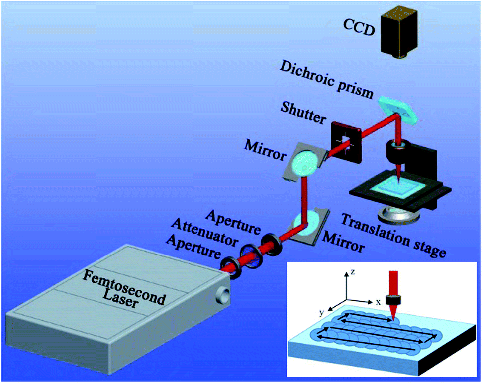 | ||
| Fig. 1 Schematic of the femtosecond laser processing system. | ||
The microstructures of the femtosecond laser-ablated PTFE surfaces were observed by the scanning electron microscope (SEM, Quantan 250 FEG, FEI, America; Flex SEM 1000, Hitachi, Japan). The wettability of the sample surfaces was investigated through a contact-angle measurement (JC2000D, Powereach, China), including the CA and sliding angle (SA). All the values were measured at three different locations, and had an error margin within ±2°. Deionized water, BSA solution (in water), cola, glucose solution (in water), orange juice, and normal saline (9 mg mL−1) were used as the tested liquids. The solutions with different pH were obtained by diluting H2SO4 and KOH with deionized water, respectively.
3. Results and discussion
Because of the extremely low surface free energy, PTFE substrate is an optimal candidate for achieving superhygrophobicity.38 The physical and chemical properties of PTFE are very stable. Even after storing in the strong acid/alkali solutions, organic solvents, and at extreme temperature (−180 to +250 °C), PTFE substrate can still maintain its original chemical composition and surface morphology. Such remarkable stability is a double-edged sword. It will bring huge difficulties to fabricate special microstructures on the PTFE surface via many common micromachining methods (e.g., template replication, self-assembly, chemical etching, and thermal annealing). The rough surface microstructure is very important for endowing the solid substrate with great liquid repellence.39–42 Fortunately, the femtosecond laser is able to ablate almost all of the known materials because of its ultra-short pulse width as well as extremely high peak intensity, even though the substrate materials have high melting point, anti-corrosion property, and high hardness/brittleness.15,43–47 Therefore, the PTFE surface was ablated by focused femtosecond laser to induce special surface texture in this experiment.Fig. 2 shows the SEM images of the textured PTFE surface which was ablated by femtosecond laser at the scanning speed of 4 mm s−1 and the scanning interval of 4 μm. The morphology of the substrate is characterized by a hierarchical porous microstructure (Fig. 2a and b). The protuberance parts between the microscale holes have the irregular shapes and are about several micrometers in size (Fig. 2c). Both the top and the side of the protuberances are decorated with nanoscale protrusions and lumps with the diameter ranging from 100 nm to 1 μm (Fig. 2d). The inset of Fig. 2d presents a schematic description of the framework of the microscale protuberances and the nanoscale protrusions/lumps. Such laser-induced porous microstructures and the hierarchical protuberances have a certain degree of the re-entrant surface curvature.39 The formation of the rough porous microstructure is ascribed to two mechanisms (the laser-induced material removal and the polymer gasification) during the interaction between the femtosecond laser pulses and the PTFE surface.48,49 Through nonlinear ionization, the energy of the laser pulses could be easily absorbed by the electrons of the PTFE surface and then transferred to the lattice. Meanwhile, high-temperature (excess of 5 × 10⁴ K) and high-pressure plasmas formed above the substrate. With the plasmas finally expanding and bursting out of the ablation spot, the ablated materials were removed from the PTFE surface. Micro/nanoscale hierarchical rough microstructure was commonly generated after the laser-induced material removal. The polymer surface was at an instantaneous molten state under laser pulses irradiation. The formation of gaseous products (i.e., gasification) also occurred and much of the generated gas ejected from the molten layer.50,51 The path of the ejected gas finally turned to solid microholes as the laser-focused point moved forward and the molten polymer immediately cooled and solidified. In addition, the ejected molten particles caused by laser ablation were able to deposit and cast onto the substrate, forming the nanoscale protrusions and lumps. As a result, the femtosecond laser ablated PTFE surface had both micro/nanoscale hierarchical microstructures and pores.
 | ||
| Fig. 2 Surface microstructure of the femtosecond laser-ablated PTFE surface. (a, b) Top-view SEM images of the resultant PTFE surface. (c, d) Side-view SEM images of the resultant PTFE surface. Inset: schematic description of the framework of the microscale protuberances and the nanoscale protrusions/lumps. | ||
Without chemical modification, the femtosecond laser-structured PTFE surface directly showed excellent repellence to various pure and complex liquids. For example, water droplet could bead up on the resultant surface with the CA of 155° and SA of 3° (Fig. 3a and b). In addition to the pure water droplet, the wettabilities of different complex liquids on the porous PTFE surface were also investigated. Fig. 3c depicts the shapes of different droplets on the as-prepared surface. All the droplets could maintain a spherical shape. The measured CAs were 150.5° (10000 ppm BSA), 152° (cola), 155° (10000 ppm glucose), 151° (juice), and 155° (saline), respectively (Fig. 3b and Table 1). These CA values are above 150°, demonstrating that the laser-induced porous PTFE surface exhibits superhygrophobicity to different complex liquids. The BSA, cola, glucose, juice, and saline droplets could easily roll away the resultant surface with the SA smaller than 10° (Fig. 3b and Table 1), indicating ultralow adhesion between the superhygrophobic surface and these liquids. The repellence to various complex liquids allows the as-prepared PTFE surface to have a wider application area than the superhydrophobic materials.
 | ||
| Fig. 3 Wettability of the femtosecond laser-ablated PTFE surface. (a) Shape of a water droplet on the structured surface. (b) CA and SA values of different liquid droplets on the laser-structured PTFE surface. The insets are the static shapes and rolling snapshots of different liquid droplets on the PTFE surface. (c) Photography of various liquid droplets on the as-prepared superhygrophobic surface. | ||
| Liquid | Surface tension (mN m−1) | CA (°) | SA (°) |
|---|---|---|---|
| Juice | 57.7 | 151 | 7 |
| Saline | 65.0 | 155 | 9 |
| Water | 72.4 | 155 | 3 |
| Cola | 74.2 | 152 | 2 |
| 10000 ppm glucose |
88.5 | 155 | 1.5 |
| 10000 ppm BSA |
101.6 | 150.5 | 5 |
Table 1 shows the surface tension of different complex liquids and the wettability of those liquid droplets on the laser-structured PTFE surface. It can be found that the wettability of those liquids is not only determined by the surface tension, in comparison to pure water and oils. Many other properties (such as chemical composition, viscosity, and concentration) may also have important influence on the wettability of the complex liquids.
Fig. 4a shows the influence of the liquid concentration on the wettability of the BSA droplet on the laser-treated PTFE surface. As the concentration of the BSA liquid increases from 100 to 50000 ppm, all the measured CA values are higher than 150° and the SA values are less than 10°. The result demonstrates that the PTFE surface has superhygrophobicity and very low liquid adhesion in a wide range of BSA concentration. Such a range is much wider than that reported in Zhang's work (1000 ppm).52 Only when the concentration further reaches up to 100000 ppm, the CA decreases to 148° and the SA increases to 13°, indicating that the superhygrophobicity starts to weak beyond a critical value (50000 ppm). Similarly, the surface can also exhibit superhygrophobicity to the glucose droplet with different concentration (Fig. 4b). As the concentration increases from 100 to 100000 ppm, the CA values (≥153.5°) and the SA values (≤2°) of the glucose droplets on the sample surface do not have a significant change. In practical applications, the liquids inevitably have acid–base property. Strong acid or alkali solutions will cause the different degree of corrosion damage to the material surface. Fig. 4c describes the wettability of H2SO4 and KOH droplets with different pH on the sample surface. All the measured CA values are above 150° with the pH ranging from 2 to 12. Therefore, the resultant superhygrophobic surface is also able to repel strong acid/alkaline solutions.
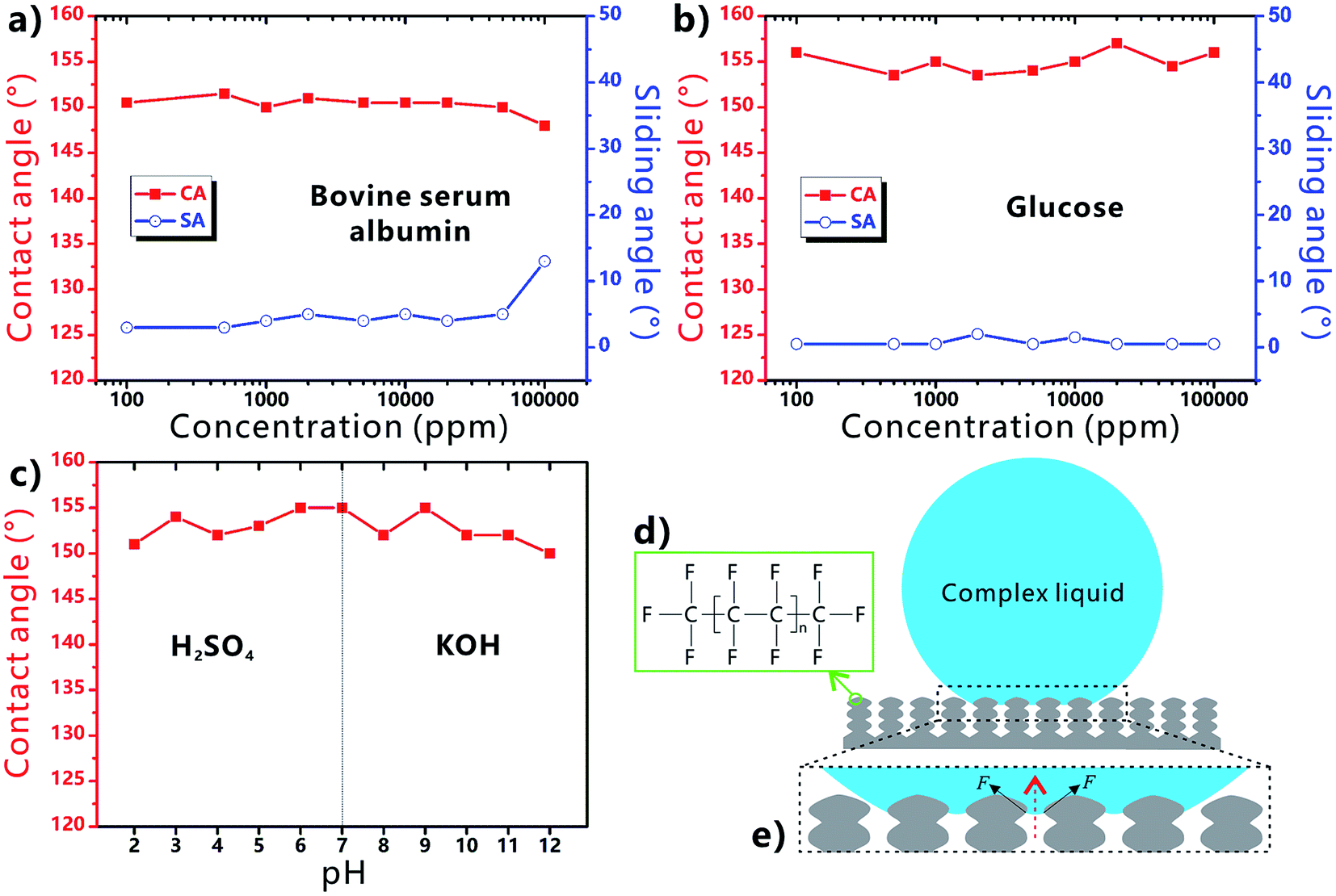 | ||
| Fig. 4 Wettability of different liquid droplets on the femtosecond laser-ablated PTFE surface. (a) Bovine serum albumin with different concentration. (b) Glucose with different concentration. (c) H2SO4 and KOH solutions with different pH. (d) Chemical formula of the PTFE. (e) Contact model between the complex liquid droplet and the laser-induced microstructure. | ||
The excellent liquid repellence of the laser-structured PTFE surface is attributed to both the chemistry and the femtosecond laser-induced special microstructure of the PTFE surface. There are a large amount of –CF3 and –CF2 groups on the PTFE surface (Fig. 4d). Those groups have the lowest surface free energy in comparison to other kinds of chemical groups.39,53 It has been demonstrated that even the liquid droplet with low surface tension can be repelled by the proper re-entrant microstructures.39 If the Young's CAs of the complex liquids on the flat solid substrate are less than 90°, the liquids are unable to be at the stable Cassie state on a textured surface without re-entrant structure because of the inherently hygrophilic property. However, when the complex liquid droplet is placed on the femtosecond laser-ablated PTFE surface, a trapped air cushion will form between the droplets and the sample surface. As shown in Fig. 4e, many convex liquid meniscuses in the downward direction form between the surface microstructure (i.e., the protuberance parts between the microscale holes). The meniscus gives rise to an upward net traction on the liquid/air interface, which is inclined to drive the liquid/air interface to recede to the top edge of the microstructures.39 Such net traction can prevent the complex liquids from further penetrating into the microholes. As a result, the substrate is difficult to be wetted by the complex liquids and the droplets are at the robust Cassie state on the re-entrant porous microstructure. By contrast, regarding the surface microstructure without re-entrant curvature, the hygrophilic substrate is easily wetted by the liquid because the concave liquid meniscuses in the upward direction can cause a downward net traction on the liquid/air interface.39 Therefore, the combination of the ultralow surface energy of the PTFE material, the laser-induced rough micro/nanoscale hierarchical microstructure, and the partly re-entrant surface curvature of the porous structure play a crucial role in the formation of the superhygrophobicity of the femtosecond laser-ablated PTFE surface.
During the femtosecond laser treatment, the scanning speed and the interval of the scanning lines can be easily changed by the control program. Every laser pulse can ablate a single crater on the PTFE surface. When the (v, d) is smaller than (12 mm s−1, 12 μm), the adjacent craters are strongly overlapped, forming uniform rough surface microstructures (Fig. 5a–c). For the (v, d) above (12 mm s−1, 12 μm), the craters keep their inherent shape and are separated with each other (Fig. 5d–f), because the distance between the craters is larger than the diameter of the craters. Non-ablated region appears between the micro-craters. As shown in Fig. 5g, as the (v, d) increases from (4 mm s−1, 4 μm), to (6 mm s−1, 6 μm), (8 mm s−1, 8 μm), and then to (10 mm s−1, 10 μm), the CA to a water droplet on the surface decreases from 155°, to 154°, 152°, and then to 151°. With further increasing the average distance of the laser ablated points, the CA continues to decrease from 149° (12 mm s−1, 12 μm) to 144° (14 mm s−1, 14 μm), and then to 141° (16 mm s−1, 16 μm). Regarding the SA values, they keep no more than 10° for the case of (4 mm s−1, 4 μm) and (6 mm s−1, 6 μm), indicating the ultralow liquid adhesion of the as-prepared surfaces. The SA increases from 5° to 13°, 29°, and then to 90° (droplet sticking on the surface even when the sample is vertical) with the (v, d) increasing from (6 mm s−1, 6 μm) to (12 mm s−1, 12 μm). Therefore, the CA decreases and the SA increases with increasing the v and d. Such a change trend is ascribed to the decline of the average surface roughness; that is, the laser ablation will become weaker and more non-ablated region appears as the v and d increase.
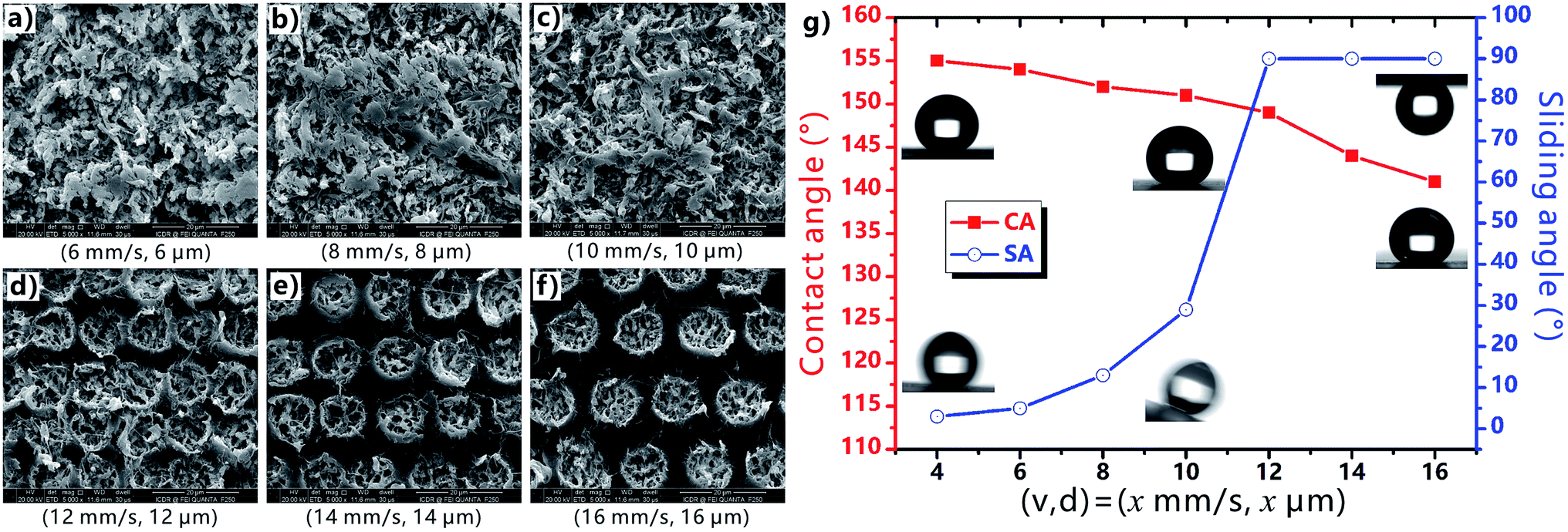 | ||
| Fig. 5 Surface microstructures and wettability of the PTFE surface fabricated at different laser scanning speeds and the intervals of scanning lines. (a–f) SEM images of the laser-ablated surfaces with different (v, d): (a) (6 mm s−1, 6 μm), (b) (8 mm s−1, 8 μm), (c) (10 mm s−1, 10 μm), (d) (12 mm s−1, 12 μm), (e) (14 mm s−1, 14 μm), and (f) (16 mm s−1, 16 μm). (g) The CA/SA values of a water droplet on the laser-structured surface fabricated at different (v, d). Insets: static shape and dynamic behavior of a water droplet on the corresponding samples. | ||
Durability is very important for the laser-structured superhygrophobic surface in practical long-term applications.54–56 Fig. 6a and b shows the wettability of the as-prepared PTFE surface after the storage at different temperature for 1 h. Even though the sample is heated at 200 °C, the CA values of both water droplet and BSA droplet on the PTFE surface are larger than 150° and the corresponding SA values are smaller than 10°. Therefore, the rough PTFE surface keeps its superhygrophobicity after heating treatment. Wear resistance is also investigated by a standard abrasion test. A sandpaper (800 mesh) is used as the friction mating, and the sample with a loading weight of 50 g is pulled forward for 10 cm on the sand paper. It is found that the surface can maintain superhygrophobicity and ultralow liquid adhesion to water and BSA droplets within 12 abrasion cycles, demonstrating good abrasion-resistant ability of the laser-structured PTFE surface (Fig. 6c and d). In addition, the superhygrophobic PTFE surface is still able to repel water and BSA droplets after immersion in a series of corrosive solutions for 24 h, including 10 M sodium hydroxide solution, 98% concentrated sulfuric acid, 40% hydrofluoric acid solution, and even aqua regia (Fig. 6e and f). Such durability of the superhygrophobicity is ascribed to the inherent chemical inertness of the PTFE substrate and the laser-induced surface microstructures.
 | ||
| Fig. 6 Durability of the femtosecond laser-induced superhygrophobic PTFE surface. (a, b) Wettability of the samples after storing at different temperature for 1 h. (c, d) Wettability of the samples after suffered from different abrasion cycles. (e, f) Wettability of the samples after immersion in different corrosive solutions for 24 h. The tested liquid in (a, c and e) is water, while that in (b, d and f) is 10000 ppm BSA. | ||
4. Conclusions
The hierarchical porous surface microstructure with a large number of microscale pores and a certain degree of re-entrant surface curvature is created on the PTFE substrate through one-step femtosecond laser ablation. Without the need of further chemical modification, the resultant surface shows superhygrophobicity and has great ability to repel various pure and complex liquids, such as water, 10000 ppm BSA, cola, 10000 ppm glucose, juice, and saline, because these droplets can be at the robust Cassie state on the laser-induced special surface microstructure. The excellent superhygrophobicity is ascribed to the combined effect of the ultralow surface energy of the PTFE material, the laser-induced rough micro/nanoscale hierarchical structure, and the partly re-entrant surface curvature of the porous structure. We believe that the resultant superhygrophobic surfaces will have potential applications in cell engineering, medical instruments, food packaging, microfluidics technology, chemical engineering, etc.
Author contributions
J. Y. designed the experiments and wrote the manuscript. M. X. performed all of the experiments. F. C. directed and supervised the research. Other authors contributed toward significant discussions and revised the paper.Conflicts of interest
The authors declare no competing financial interest.Acknowledgements
This work is supported by the National Key Research and Development Program of China under the Grant no. 2017YFB1104700, the National Science Foundation of China under the Grant no. 51335008, 61875158, and 61805192, China Postdoctoral Science Foundation under the Grant no. 2016M600786, the Collaborative Innovation Center of Suzhou Nano Science and Technology. The SEM work was done at International Center for Dielectric Research (ICDR), Xi'an Jiaotong University.References
- W. Barthlott and C. Neinhuis, Planta, 1997, 202, 1–8 CrossRef CAS.
- X. Gao and L. Jiang, Nature, 2004, 432, 36 CrossRef CAS PubMed.
- Y. Zheng, X. Gao and L. Jiang, Soft Matter, 2007, 3, 178–182 RSC.
- X. Gao, X. Yan, X. Yao, L. Xu, K. Zhang, J. Zhang, B. Yang and L. Jiang, Adv. Mater., 2007, 19, 2213–2217 CrossRef CAS.
- A. R. Parker and C. R. Lawrence, Nature, 2001, 411, 33–34 CrossRef PubMed.
- B. Bhushan, Philos. Trans. R. Soc., A, 2009, 367, 1445–1486 CrossRef CAS PubMed.
- T. Darmanin and F. Guittard, Mater. Today, 2015, 18, 273–285 CrossRef CAS.
- T.-L. Zhang, Q.-D. Chen, Z. Jin, E. Kim and H.-B. Sun, Nanoscale, 2012, 4, 4858–4869 RSC.
- M. Liu, Y. Zheng, J. Zhai and L. Jiang, Acc. Chem. Res., 2010, 43, 368–377 CrossRef CAS PubMed.
- Y. Tian, B. Su and L. Jiang, Adv. Mater., 2014, 26, 6872–6897 CrossRef CAS PubMed.
- L. Wen, Y. Tian and L. Lei, Angew. Chem., Int. Ed., 2015, 54, 3387–3399 CrossRef CAS PubMed.
- H. Bellanger, T. Darmanin, E. T. de Givenchy and F. Guittard, Chem. Rev., 2014, 114, 2694–2716 CrossRef CAS PubMed.
- J.-N. Wang, Y.-L. Zhang, Y. Liu, W. Zheng, L. P. Lee and H.-B. Sun, Nanoscale, 2015, 7, 7101–7114 RSC.
- J. Yong, S. C. Singh, Z. Zhai, F. Chen and C. Guo, Langmuir, 2019, 35, 921–927 CrossRef CAS PubMed.
- J. L. Yong, F. Chen, Q. Yang and X. Hou, Soft Matter, 2015, 11, 8897–8906 RSC.
- S. Nishimoto and B. Bhushan, RSC Adv., 2013, 3, 671–690 RSC.
- K. Liu and L. Jiang, Annu. Rev. Mater. Res., 2012, 42, 231–263 CrossRef CAS.
- M. Barberoglou, V. Zorba, E. Stratakis, E. Spanakis, P. Tzanetakis, S. H. Anastasiadis and C. Fotakis, Appl. Surf. Sci., 2009, 255, 5425–5429 CrossRef CAS.
- M. Nosonovsky and V. Hejazi, ACS Nano, 2012, 6, 8488–8491 CrossRef CAS PubMed.
- M. J. Kreder, J. Alvarenga, P. Kim and J. Aizenberg, Nat. Rev. Mater., 2016, 1, 1–15 Search PubMed.
- J. Lv, Y. Song, L. Jiang and J. Wang, ACS Nano, 2014, 8, 3152–3169 CrossRef CAS PubMed.
- S. Pan, A. K. Kota, J. M. Mabry and A. Tuteja, J. Am. Chem. Soc., 2013, 135, 578–581 CrossRef CAS PubMed.
- F. Shi, J. Niu, J. Liu, F. Liu, Z. Wang, X.-Q. Feng and X. Zhang, Adv. Mater., 2007, 19, 2257–2261 CrossRef CAS.
- Y. Wu, Q. Wei, M. Cai and F. Zhou, Adv. Mater. Interfaces, 2014, 1, 1400392 Search PubMed.
- E. P. Ivanova, J. Hasan, H. K. Webb, G. Gervinskas, S. Juodkazis, V. K. Truong, A. H. F. Wu, R. N. Lamb, V. A. Baulin, G. S. Watson, J. A. Waston, D. E. Mainwaring and R. J. Crawford, Nat. Commun., 2013, 4, 2338 CrossRef PubMed.
- E. Fadeeva, V. K. Truong, M. Stiesch, B. N. Chichkov, R. J. Crawford, J. Wang and E. P. Ivanova, Langmuir, 2011, 27, 3012–3019 CrossRef CAS PubMed.
- Z. Xue, Y. Cao, N. Liu, L. Feng and L. Jiang, J. Mater. Chem. A, 2014, 2, 2445–2460 RSC.
- J. Yong, J. Huo, F. Chen, Q. Yang and X. Hou, Phys. Chem. Chem. Phys., 2018, 20, 25140–25163 RSC.
- J. L. Yong, Q. Yang, F. Chen, D. Zhang, U. Farooq, G. Du and X. Hou, J. Mater. Chem. A, 2014, 2, 5499–5507 RSC.
- J. Yong, S. C. Singh, Z. Zhai, J. Huo, F. Chen and C. Guo, ChemNanoMat, 2019, 5, 241–249 CrossRef CAS.
- J. Li, Z. Jing, F. Zha, Y. Yang, Q. Wang and Z. Lei, ACS Appl. Mater. Interfaces, 2014, 6, 8868–8877 CrossRef CAS PubMed.
- A. Vitale, M. Quaglio, S. L. Marasso, A. Chiodoni, M. Cocuzza and R. Bongiovanni, Langmuir, 2013, 29, 15711–15718 CrossRef CAS PubMed.
- K. W. Kwon, S. S. Choi, S. H. Lee, B. Kim, S. N. Lee, M. C. Park, P. Kim, S. Y. Hwang and K. Y. Suh, Lab Chip, 2007, 7, 1461–1468 RSC.
- A. Marmur, Soft Matter, 2012, 8, 8667–8670 RSC.
- J. L. Yong, F. Chen, Q. Yang, G. Du, C. Shan, H. Bian, U. Farooq and X. Hou, J. Mater. Chem. A, 2015, 3, 9379–9384 RSC.
- J. L. Yong, F. Chen, M. Li, Q. Yang, Y. Fang, J. Huo and X. Hou, J. Mater. Chem. A, 2017, 5, 25249–25257 RSC.
- J. Yong, F. Chen, Q. Yang, Z. Jiang and X. Hou, Adv. Mater. Interfaces, 2018, 5, 1701370 CrossRef.
- K. Tsujii, T. Yamamoto, T. Onda and S. Shibujchi, Angew. Chem., Int. Ed., 1997, 36, 1011–1012 CrossRef CAS.
- J. Yong, F. Chen, Q. Yang, J. Huo and X. Hou, Chem. Soc. Rev., 2017, 46, 4168–4217 RSC.
- H. Liu, Y. Wang, J. Huang, Z. Chen, G. Chen and Y. Lai, Adv. Funct. Mater., 2018, 28, 1707415 CrossRef.
- Z. Xue, M. Liu and L. Jiang, J. Polym. Sci., Part B: Polym. Phys., 2012, 50, 1209–1224 CrossRef CAS.
- H. Teisale, M. Tuominen and J. Kuusipalo, Adv. Mater. Interfaces, 2014, 1, 1300026 CrossRef.
- K. Sugioka and Y. Cheng, Appl. Phys. Rev., 2014, 1, 041303 Search PubMed.
- A. Y. Vorobyev and C. Guo, Laser Photonics Rev., 2013, 7, 385–407 CrossRef CAS.
- K. Sugioka and Y. Cheng, Light: Sci. Appl., 2014, 3, e149 CrossRef CAS.
- J. L. Yong, F. Chen, J. Huo, Y. Fang, Q. Yang, J. Zhang and X. Hou, Nanoscale, 2018, 10, 3688–3696 RSC.
- J. Yong, F. Chen, Y. Fang, J. Huo, Q. Yang, J. Zhang, H. Bian and X. Hou, ACS Appl. Mater. Interfaces, 2017, 9, 39863–39871 CrossRef CAS PubMed.
- J. L. Yong, F. Chen, Q. Yang, Y. Fang, J. Huo, J. Zhang and X. Hou, Adv. Mater. Interfaces, 2017, 4, 1700552 CrossRef.
- J. L. Yong, J. Huo, Q. Yang, F. Chen, Y. Fang, X. Wu, L. Liu, X. Lu, J. Zhang and X. Hou, Adv. Mater. Interfaces, 2018, 5, 1701479 CrossRef.
- T. Efthimiopoulos, Ch. Kiagias, G. Heliotis and E. Helidonis, Can. J. Phys., 2000, 78, 509–519 CrossRef CAS.
- J. Krüger, S. Martin, H. Mädebach, L. Urech, T. Lippert, A. Wokaun and W. Kautek, Appl. Surf. Sci., 2005, 247, 406–411 CrossRef.
- L. Fan, B. Li and J. Zhang, Adv. Mater. Interfaces, 2015, 2, 1500019 CrossRef.
- J. Genzer and K. Efimenko, Biofouling, 2006, 22, 339–360 CrossRef CAS PubMed.
- W. S. Y. Wong, Z. H. Stachurski, D. R. Nisbet and A. Tricoli, ACS Appl. Mater. Interfaces, 2016, 8, 13615–13623 CrossRef CAS PubMed.
- G. L. William, W. S. Y. Wong, N. Nasiri and A. Tricoli, Nanoscale, 2016, 8, 6085–6093 RSC.
- W. S. Y. Wong, G. Liu, N. Nasiri, C. Hao, Z. Wang and A. Tricoli, ACS Nano, 2017, 11, 587–596 CrossRef CAS PubMed.
Footnote |
| † These authors contributed equally to this publication. |
| This journal is © The Royal Society of Chemistry 2019 |