 Open Access Article
Photovoltaic cells as a highly efficient system for biomedical and electrochemical surface-enhanced Raman spectroscopy analysis†
K. Nicińskia,
E. Witkowskaa,
D. Korsakb,
K. Noworyta a,
J. Trzcińska-Danielewiczc,
A. Girstunc and
A. Kamińska
 *a
*a
aInstitute of Physical Chemistry, Polish Academy of Sciences, Kasprzaka 44/52, 01-224 Warsaw, Poland. E-mail: akamin@ichf.edu.pl
bDepartment of Applied Microbiology, Institute of Microbiology, Faculty of Biology, University of Warsaw, Miecznikowa 1, 02-096 Warsaw, Poland
cDepartment of Molecular Biology, Institute of Biochemistry, Faculty of Biology, University of Warsaw, Miecznikowa 1, 02-096 Warsaw, Poland
First published on 2nd January 2019
Abstract
Surface-enhanced Raman scattering (SERS) has been intensively used recently as a highly sensitive, non-destructive, chemical specific, and label-free technique for a variety of studies. Here, we present a novel SERS substrate for: (i) the standard ultra-trace analysis, (ii) detection of whole microorganisms, and (iii) spectroelectrochemical measurements. The integration of electrochemistry and SERS spectroscopy is a powerful approach for in situ investigation of the structural changes of adsorbed molecules, their redox properties, and for studying the intermediates of the reactions. We have developed a conductive SERS platform based on photovoltaic materials (PV) covered with a thin layer of silver, especially useful in electrochemical SERS analysis. These substrates named Ag/PV presented in this study combine crucial spectroscopic features such as high sensitivity, reproducibility, specificity, and chemical/physical stability. The designed substrates permit the label-free identification and differentiation of cancer cells (renal carcinoma) and pathogens (Escherichia coli and Bacillus subtilis). In addition, the developed SERS platform was adopted as the working electrode in an electrochemical SERS approach for p-aminothiophenol (p-ATP) studies. The capability to monitor in real-time the electrochemical changes spectro-electro-chemically has great potential for broadening the application of SERS.
1. Introduction
Surface-enhanced Raman scattering (SERS), due to its high sensitivity and specificity, is currently widely used as an important tool for biomedical,1–6 analytical,7,8 and environmental analysis.9,10The SERS effect, in which the scattering cross-sections are considerably enhanced for molecules upon their adsorption onto specific metallic nanostructures, relies on the combination of electromagnetic (EM) and chemical (CT) mechanisms.11 The electromagnetic enhancement is attributed to the amplification of the electromagnetic field via coupling of the radiation field with the localized surface plasmon of the metal nanostructures (LSPR; localized surface plasmon resonance). This mechanism is closely related to the morphology and dielectric environment of the plasmonic nanostructures and usually plays a crucial role in whole SERS enhancement. The localized electromagnetic field can be enhanced by ‘hot spots’, which are usually generated between the narrow gaps, edges, or clusters of metallic nanostructures. The chemical enhancement mechanism involves the photo-induced charge transfer excitation between the Fermi level of the metal and the molecular orbital of the adsorbate or vice versa.12 These two mechanisms can enhance the Raman signals of the adsorbed molecule by 5, 6, even 14 orders of magnitude.13,14 As a result SERS ensures the ultra-trace detection of analytes even down to the single molecule level.15
Apart from its ultrasensitivity and the ability to provide the chemical fingerprint of molecules, the SERS technique offers non-destructive, fast, and label-free characterization of samples. Additionally, due to developments in SERS probes strategy16–18 (Raman reporter labeled nanostructures) and recent progress in chemometrics and multivariate methods, SERS can be widely applied in multiplex analysis of complex systems such as blood or cerebrospinal fluids. All these features lead to increasing the potential of the SERS method in practical applications especially for analysis of biological material, from single macromolecules to prokaryotic19,20 and eukaryotic cells21,22 with both in vitro and ex vitro approaches.
Despite the remarkable advantages, the real-world application of SERS technique in point-of-care clinical trials is still hindered because of the difficulty in preparing ideal SERS-active substrates. For analytical applications of SERS in a portable manner, low-cost, long-term stable, highly sensitive nanostructures which additionally generate uniform and reproducible responses are required.
Nowadays, nanostructured noble metal (Ag, Au, Cu) surfaces or nanoparticle assemblies are commonly used as a SERS-active substrate. A remarkable variety of techniques – such as electrochemical methods,23 nanosphere lithography,24 electron-beam lithography,25 nanoimprinting lithography,26 vapor layer deposition,27 colloidal suspension,6 and many other methods – are currently utilized for the fabrication of well-ordered SERS nanostructures.28–33 Generally, SERS-active nanostructures include: (i) colloidal metal nanoparticles, and (ii) solid support-based substrates. Colloid-based substrates are easy to fabricate and exhibit high SERS enhancement efficiency. On the other hand, the lack of special uniformity and enhancement repeatability are their main drawbacks. Recent progress in nanotechnology has led to rapid development in the fabrication of novel solid-support based SERS substrates.34–40 These substrates have an advantage over colloidal substrates, especially in terms of stability and reproducibility. The top-down41,42 and bottom-up techniques43,44 and their combination with template-assisted approaches42,45 enable fabrication of relatively uniform and periodic structures with excellent SERS efficiency. However, in the case of solid-support-based SERS substrates, the fabrication processes are rather time-consuming and/or expensive. Additionally, many of these approaches offer SERS substrates with excellent enhancement factor values but still suffer from poor reproducibility of SERS responses.
The introduction of electrochemistry into the SERS technique opens a new path for in situ monitoring of the structural changes of adsorbed molecules, to determine their specific redox states, and to study reaction intermediates.46–50 Recently, Meneghello et al.51 have shown that electrochemical SERS analysis (deconvolution of SERS spectra recorded as a function of applied-to-electrode potential) can be used as a highly sensitive technique to measure the redox potential of the anticancer drug mitoxantrone bound to dsDNA. Mahajan et al.52 combined SERS with electrochemistry to analyse the mutations in DNA sequences. Itoh et al.48 applied SERS spectroelectrochemistry to studies of oxide chemistry at the interface between silver and gold electrodes and the selected electrolyte solution.
To conclude, there is a strong need for cheap, versatile, durable, stable SERS nanostructures which can easily be introduced to routine trial analysis – especially in portable, point-of-care applications – and may be also easily applied for SERS spectroelectrochemical measurements.
The designed SERS nanostructures exhibit the excellent sensitivity, selectivity, and reproducibility of recorded signals. It should be highlighted that, for example, for p-ATP the maximum SERS intensity (150![[thin space (1/6-em)]](https://www.rsc.org/images/entities/char_2009.gif) 000 c s−1) tolerated by a CCD camera was achieved during 3 s of spectrum accumulation at 1.5 mW power of laser (the enhancement factor (EF) was estimated to be as high as 106).
000 c s−1) tolerated by a CCD camera was achieved during 3 s of spectrum accumulation at 1.5 mW power of laser (the enhancement factor (EF) was estimated to be as high as 106).
These Ag/PV substrates have also been successfully applied to the SERS-based analysis of prokaryotic and eukaryotic cells: (i) cancer cells, i.e. renal carcinoma Caki-1 cells, and (ii) pathogens i.e. Escherichia coli and Bacillus subtilis. Additionally, the Ag/PV possess conductive paths between the array of periodic cones and can also be used as an electrode in spectroelectrochemical setup. We have demonstrated the ability to monitor the potential-dependent SERS spectra of p-ATP to understand the SERS features of biofunctional molecules.
2. Materials and methods
2.1. Chemicals and materials
P-aminothiophenol (p-ATP) and phosphate-buffered saline (PBS) packs (10 mM, pH = 7.2) were obtained from Sigma-Aldrich (Dorset, UK) and used without further purification. Water (resistivity over 18 MΩ), purified using a Milli-Q plus 185 system was used throughout the process. PV panels were obtained from Bruk-Bet Solar Tarnów, Poland as a post-production residue. Silver sputtering target was obtained from Mennica Metale Szlachetne Radzymin, Poland.2.2. Cell cultivation and preparation
We perform all of our experiments on human cancer cell line Caki-1 which is commercially available. The cell line is purchased from the ATCC (https://www.lgcstandards-atcc.or).The Caki-1 cells were cultured in RPMI-1640 medium, supplemented with 10% FBS, penicillin (100 U ml−1), and streptomycin (100 μg ml−1). The culture was maintained in a 95% humidified atmosphere of 5% CO2 at 37 °C. For the experiments the cells were cultured in 25 cm2 cell culture flasks. After reaching 80% of confluence, the cells were washed with PBS, trypsinized (0.05% trypsin, 0.02% EDTA solution), collected, and centrifuged at 250 × g for 5 min at room temperature. Then cells were washed with PBS and centrifuged again. After centrifugation cells were re-suspended in 20 μl of PBS and stored on ice. All the media and reagents were obtained from Sigma-Aldrich (St. Louis, MO, USA).
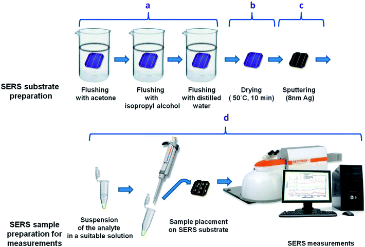
Bacterial species used in the experiment were obtained from the Department of Bacterial Genetics, University of Warsaw, Poland. To multiply microbial organisms, we cultivated them in LB agar (Lysogeny broth agar) at 37 °C for 24 h. After that 3–4 single bacterial colonies of ∼2 μm in diameter were suspended in 500 μl of 0.9% NaCl solution (saline solution) and centrifuged for 5 min at 4000 rpm. After centrifugation the supernatant was discarded and the bacterial cells were re-suspended in 500 μl of saline solution. The centrifugation process in the saline solution was repeated 4 times to obtain a solution of clean bacterial cells. In the final step the supernatant was completely discarded and the bacteria cells were transferred via pipette and placed onto a SERS substrate (Fig. 2). The SERS measurements (Fig. 2d) were taken after 10 minutes, to let the SERS substrate dry.
2.3. Instrumentation
The SERS spectra were recorded from 40-90 different points in mapping mode from a 20 × 40 μm area of SERS substrate. The time required for completing a single SERS spectrum was 3 seconds for p-ATP and 6 seconds for bacterial and cancer cells.
The obtained spectra were processed with OPUS software (Bruker Optic GmbH 2012 version). The spectra were smoothed with a Savitzky–Golay filter; the background was removed using baseline correction.
2.4. Preparation of the SERS platform and sample measurement
The general scheme of preparing the SERS-active platform and measurement of the sample is shown in Fig. 2. Photovoltaic sample at 40 × 40 mm was placed in a baker filled with acetone. The first step was sonication for 10 minutes in an ultrasonic bath at 50 °C (Fig. 2a). Then the acetone was exchanged and the step was repeated. After 10 minutes the baker was filled with isopropyl alcohol and the sample was sonicated for 10 minutes at temperature 50 °C (Fig. 2b). Then the sample was sonicated for 10 minutes in distilled water (Millipore) at ambient temperature (Fig. 2c). The cleaned photovoltaic device was then dried for 30 minutes at 50 °C (Fig. 2d) and placed in a sterile Petri dish or immediately placed in a Physical Vapor Deposition (PVD) device and sputtered with a layer of silver (Fig. 2d). The prepared SERS platform is ready for use.To measure bacteria, we placed a small amount of bacteria in an Eppendorf together with saline solution, vortexed and placed on the platform with a pipette. The cancer cells also in PBS buffer were deposited onto the SERS substrate and dried. The SERS measurements were performed up to three hours after cell preparation to avoid damaging them. The platforms with bacteria and cancer cells on the surface were placed under a microscope and subjected to measurement for 15 minutes (Fig. 2).
3. Results and discussion
3.1. Characterization of PV surfaces
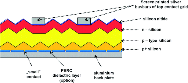
In our experiments we used four different photovoltaic (PV) systems (see Table 1), made of three main layers53 (Fig. 3). The top layer consists of blue silicon nitride anti-reflection coating deposited in plasma-enhanced chemical vapor deposition (PECVD) and silver busbars, which play the role of grid contacts. The detailed analysis of PV production is presented in ESI (Chapter 1.1).† Fig. S1† presents the SEM images of the four types of analyzed PV devices. We have tested two polycrystalline silicon devices named 1m and 1-types, and two monocrystalline silicon systems named 2 and 3-types. According to their description summarized in Table 1, the devices 1m and 1-types differ from each other in the method of preparing the silicon nitride layer (various chemical vapor deposition processes), which is reflected in the visual properties of these panels, i.e. their colors and gloss. Additionally, the SEM images (see Fig. 1) of 1m and 1-types of devices clearly revealed the difference in their morphology. The SEM image of 1m sample, shows that the porous silicon consisted of the network of pores from 200 to 400 nm. The sample named 1 (Fig. S1(B)†) reveals micrometer sized silicon barrels arranged into plait-like structures. The morphologies of samples named 2 and 3-types (Fig. S1(C and D)†) are completely different from morphologies of 1 and 1m-types of analyzed samples but they are very similar to each other. Both, 2 and 3-types of PV devices exhibit the pyramid-like micrometer sized silicon structures.| Name of the sample | Type of crystallite | Quantity of top silver busbars/single photo panel | PERC | Color (visual observation) | Thickness of Si | Thickness range of antireflection layer |
|---|---|---|---|---|---|---|
| 1-Type | Poly | 4 | No | Different shades of blue from front and side | 200 μm ± 20 μm | 88.5–98.8 nm |
| 1m-type | Poly | 4 | No | Blue or dark blue from front and dark blue from side | 200 μm ± 20 μm | 88.5–98.8 nm |
| 2-Type | Mono | 3 | Yes | Dark blue from front | 210 μm ± 20 μm | 85.9–88.5 nm |
| 3-Type | Mono | 4 | No | Black blue from front | 210 μm ± 20 μm | 75.6–85.9 nm |
In the next step, PV devices were cleaned and then covered by a silver layer with different thicknesses using the physical vapor deposition (PVD) method. Fig. 4 and S2† show the SEM and AFM pictures at different magnifications of all the PV systems, respectively. The SEM images at high magnification exhibit homogeneously distributed silver nanostructures onto a PV support. Image analysis was performed for each sample to obtain the size distribution of silver nanostructures. A representative image and its histogram for sample “1m-type” is presented in Fig. 4, whereas histograms for all samples are presented in Fig. S3.† As can be seen, silver nanostructures are closely and regularly distributed across the Ag/PV surfaces and their median size is below 30 nm. Fig. S2† additionally presents the AFM images at two different magnifications of all tested Ag/PV SERS-active substrates sputtered with 8 nm layer of silver. These results confirm that the enveloped method of fabrication of the SERS-active substrate offers homogeneous coverage of the PV surface with the layer of silver. The degree of surface roughness RMS (root mean square) of all tested PV samples was determined using AFM (Fig. S2†) and is summarized in Table 3. It should be highlighted, that all samples have over 20 times higher value of RMS than ion-etched silicon. For PV based surfaces RMS varies from 120 ± 6 nm to 364 ± 58 nm, where etched silicon possesses roughness at a level of 6.6 ± 0.6 nm (see Fig. S4 in ESI†). The effect of surface roughness on plasmonic structures determinates the SERS efficiency.54 The observed higher SERS activity for rougher surfaces is related to the generation of a larger amount of “hot-spots”,55 which determine the localized plasmon effect and SERS intensity.
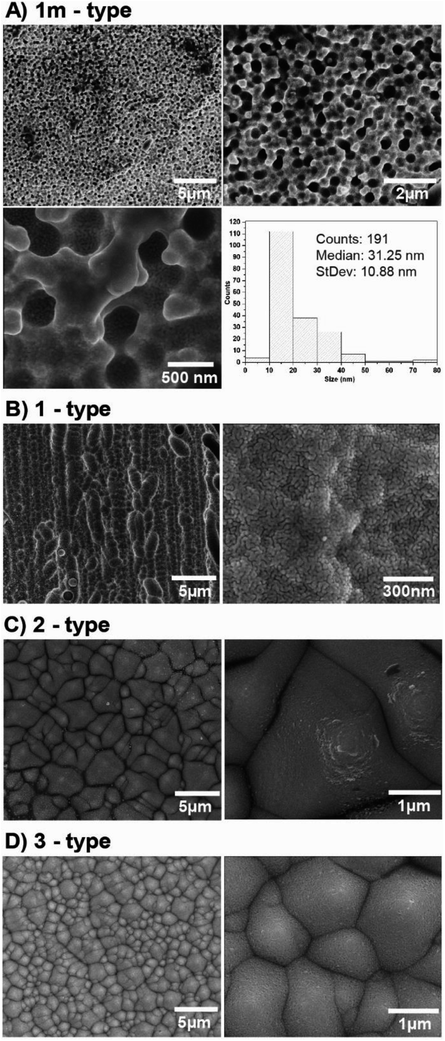 | ||
| Fig. 4 SEM images at different magnifications of Ag/PV SERS-active substrates sputtered with 8 nm layer of silver via PVD technique. | ||
3.2. XPS analysis of Ag/PV SERS substrates
The surface compositions of PV based SERS substrates were investigated using X-ray photoelectron spectroscopy (XPS). Fig. S5† depicts the full spectra from XPS analysis on four different PV-based SERS substrates before (yellow rows) and after (blue rows) coating with 8 nm of silver.All XPS results were summarized in Table 2, which presents the surface concentrations of detected elements. As can be seen, for Ag coated PV substrates the major component detected through XPS corresponds to pure silver. The additional presence of oxygen- and carbon-related XPS peaks can be associated with some sample contamination,56 which probably arises during the PVD procedure (deposition of silver). In the case of samples 1m, 2, and 3 (see Fig. S5†), very weak peaks at 155 eV appear, which are attributed to Si (2s) crystalline Si bonding57 (crystalline silicon is the main compound of photovoltaic arrays). In the case of “raw” photovoltaic samples (named 1, 1m, 2, and 3) the observed peaks correspond to the surface composition of PV samples described in Paragraph 3.1.
| Sample label | Atomic concentration (at%) | ||||||||
|---|---|---|---|---|---|---|---|---|---|
| O | Si | C | N | F | Sb | Pb | Na | Ag | |
| 1 | 29.0 | 25.6 | 23.5 | 21.0 | 0.5 | 0.2 | 0.1 | <0.1 | 0.0 |
| 1m | 29.6 | 34.8 | 12.8 | 22.2 | <0.1 | 0.4 | 0.1 | 0.2 | 0.0 |
| 2 | 33.7 | 31.7 | 11.2 | 22.0 | 0.1 | 0.1 | 0.6 | 0.5 | 0.0 |
| 3 | 48.0 | 27.8 | 11.4 | 11.7 | <0.1 | 0.6 | 0.3 | 0.3 | 0.0 |
| 1(Ag) | 12.6 | 0.0 | 25.9 | 0.0 | 0.0 | 0.0 | 0.0 | 0.0 | 61.5 |
| 1m(Ag) | 15.7 | 2.8 | 29.7 | 0.0 | 0.0 | 0.0 | 0.0 | 0.0 | 51.8 |
| 2(Ag) | 15.2 | 2.8 | 22.6 | 0.0 | 0.0 | 0.0 | 0.1 | 2.0 | 57.4 |
| 3(Ag) | 16.8 | 3.4 | 39.9 | 0.0 | 0.0 | 0.0 | <0.1 | 0.0 | 39.8 |
3.3. SERS investigations
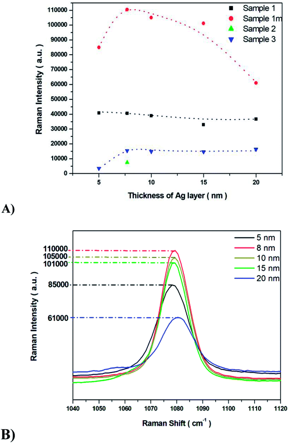
The SERS properties of all fabricated Ag/PV substrates (sensitivity, selectivity, and reproducibility) were tested using p-aminothiophenol (p-ATP) as a standard probe molecule. The intensities of p-ATP SERS signals depend on the plasmonic features of the SERS substrate and the conditions of measurement.58–60 The p-ATP molecules efficiently bind through its thiol groups to the silver layer of the SERS-active surface and thus give a strong SERS response. As was mentioned above, the PV arrays were coated with noble metal through a PVD process to gain the SERS activity. It was found that the thickness of the deposited metal film determines both the size and density of the formed metal nanostructures.43 Fig. 5 depicts the relation between the intensity of the 1078 cm−1 band of p-ATP and the thickness of the silver film. As can be seen (Fig. 5), for sample 1m increasing the thickness of the silver layer from 5 to 8 nm also increases the intensity of the marker band at 1078 cm−1, however further increase in the thickness (from 10 nm to 20 nm) of the silver leads to noticeably decrease the intensity of this band. Therefore, an 8 nm thick silver layer appears as the most optimal to generate appropriate silver nanostructure size and distribution for effective plasmon resonance effect. Moreover, thick (>10 nm) silver layer placed on the photovoltaic support, do not replicate nanostructured morphology, which is crucial to obtain high EF (thick, continuous silver film which does not possess SERS activity). In the case of samples named 1 and 3 increasing the thickness of the silver layer from 5 to 20 nm leads to a slight variety in the intensity of the marker band. For sample 2 the SERS enhancement has been observed only for 8 nm of deposited Ag. The sample exhibited very low SERS activity due to its morphology: RMS value of 365 nm ± 58 nm is the highest for the all of the examined samples. As we can see from SEM image (Fig. 4C), the surface of this SERS platform is non-uniform and is composed of different ‘islands’ of size from hundreds of nm up to five μm. Taking this into account, the number of possible hot-spots is very low, therefore for 8 nm thick silver layer the low enhancement has been observed. After we increased the thickness of the deposited silver, we totally cover the roughness responsible for the SERS enhancement, therefore we do not record any reasonable SERS response.Common metal nanostructures applied as SERS active substrate are silver and gold.61 In our studies, we also tested the SERS efficiency of ‘1m type’ of PV system covered with a gold layer at different thicknesses. As we can see from Fig. S6† the most intensive marker band at 1078 cm−1 appeared at 5 nm of Au thickness but it is still 20 times lower that the intensity of this band recorded for the Ag layer. To conclude: (i) the PV type 1m (Table 1, Fig. 4) and (ii) 8 nm thickness of the Ag metal film lead to the optimal morphology for the most efficient SERS response. This particular structure has been applied to our further studies.
The SERS spectra of p-ATP recorded from four different SERS substrates (1m, 1, 2, and 3) coated with selected 8 nm thickness are recorded and presented in Fig. 6.
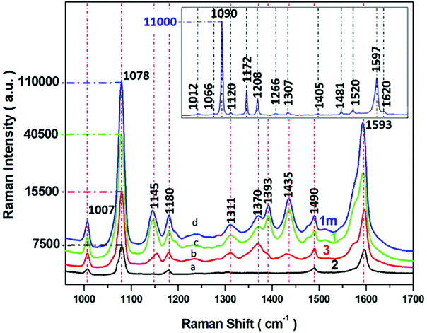 | ||
| Fig. 6 SERS spectra of p-ATP recorded from four different SERS substrates (a–d) with varying morphology of PV systems (according to parameters described in Table 1). Experimental conditions: 5 mW of 785 nm excitation, 2 × 2 seconds acquisition time. Insert presents the normal Raman spectrum p-ATP in neat solid state. Each SERS spectrum was averaged from forty measurements in different places on the SERS surface. | ||
Insert in Fig. 6 shows the normal Raman spectrum of solid p-ATP deposited on a glass slide. The spectrum was dominated by a prominent band at 1090 cm−1 which was assigned to the C–S stretching vibration. A medium band at 1597 cm−1 is attributed to C–C stretching modes. The normal Raman spectrum also reveals three very weak peaks at 1007, 1172, and 1481 cm−1 assigned to C–C and C–C–C bending, C–H bending, and a combination of C–C stretching and C–H bending, respectively. It is well known58,59,62,63 that all these recorded bands are assignable to the totally symmetric a1 vibrational modes64 (in plane, in phase modes) of p-ATP, as presented in Table S1.† For comparison, the SERS spectral features of p-ATP adsorbed from 10−6 M ethanol solution onto four obtained Ag/PV surfaces were recorded and presented in Fig. 6a–d. The two a1-type bands at 1078 and 1593 cm−1 appear also in the SERS spectra. The weak band observed in normal Raman spectrum at 1172 cm−1 appears also in the SERS spectrum at 1180 cm−1. But, in contrast to a normal Raman spectrum, the intensive b2-type bands (out of plane vibrational modes) at 1370, 1145, have been observed. The appearing of b2-type bands is related to the contribution of CT mechanism (metal–molecule charge transfer process) to total SERS enhancement.65,66 Moreover, the strong enhancement of these bands indicate the perpendicular orientation of p-ATP molecules onto the Ag/PV surfaces.67 A detailed examination of recorded SERS spectra onto four different Ag/PV surfaces revealed the higher total intensity of p-ATP for 1m surface. Additionally, the SERS efficiency of all obtained types of surfaces (1m, 1, 2, 3) has been quantified by the calculated enhancement factor (EF) using eqn (1).
| EF = (ISERS/NSERS)/(INR/NNR) | (1) |
The data summarized in Table 3 clearly indicate that the optimal morphology (Fig. 4 and S2†) corresponds to the 120 ± 6 nm roughness of the surface (RMS value in Table 3). As was mentioned above, the SERS activity is related to the surface roughness of plasmonic nanostructures. The value of roughness (120 ± 6 nm) which corresponds to the most efficient SERS properties is the lowest among all the tested PV surfaces, but is still even 100 times higher in comparison to the standard etched silicon (6.6 ± 0.6 nm) commonly used as a SERS substrate.
It should be noticed, that sample 1m exhibits completely different morphology than the rest of the studied samples (the porous silicon consisted of the network of pores), whereas the rest of the analyzed sampled do not possess any porous structure and exhibits the pyramid/barrel-like micrometer-sized structures (see Fig. S1† and 4). For sample 1, 2, and 3, both the island-like morphology instead of a homogeneous film and high roughness shows complex relations, which as a result do not provide high SERS enhancement. The SERS activity of morphology presented in Fig. 4A is widely recognized in the literature.68–71 This rougher surface generates the appropriate amount of “hot-spots”, which most efficiently support the localized plasmon resonance response. Our experiments demonstrate that, in addition to thickness, also the roughness of the metallic layer is a crucial parameter in SERS enhancement. However, there are no consistent studies in literature, which intended to understanding the influence of thickness of the metal film and the roughness of the substrate on the SERS efficiency.
It should be highlighted that the developed SERS-active surface achieved excellent sensitivities for p-ATP also at concentrations as low as 10−9 M with an enhancement factor of 1.3 × 10³ (Fig. S6†).
3.4. Biomedical applications of a Ag/PV substrate. Comparison of prokaryotic and eukaryotic cells
Rapid, cost-effective, and sensitive identification of cancer cells or pathogens is a challenging task crucial in both research and clinical areas. For example, the detection and monitoring of circulating tumor cells (CTCs) in blood is an important strategy for early cancer detection, monitoring of therapeutic response and cancer therapy treatments. Rapid and early detection of bacterial pathogens is critical in bacteremia and sepsis diagnosis. Surface-enhanced Raman spectroscopy is a highly sensitive and specific method that allows detection and characterization of various molecules through the capability to generate their molecular fingerprint signals. Therefore, SERS may be applied to differentiate bacterial strains or cancer from normal cells based on changes in their biomolecular signatures revealed by the SERS response.In order to validate the performance of our SERS surface in terms of analytical application, we collected SERS spectra of renal cell carcinoma (Caki-1) and Bacillus subtilis and Escherichia coli as examples of cancer and bacterial species, respectively.
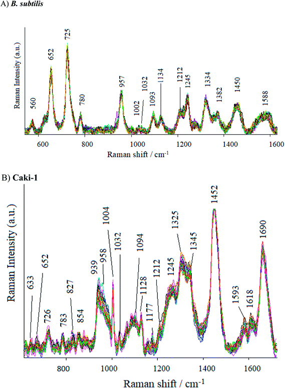
As can be seen in Fig. 7, the SERS spectrum of B. subtilis (recorded at 70 points across the surface) shows major bands at around 652, 725, 957, 1093, 1275, 1334, 1382, 1450 and 15![[thin space (1/6-em)]](https://www.rsc.org/images/entities/char_2009.gif) 880 cm−1. Some weak bands at around 560, 780, 850, 1002, 1030, 1212 cm−1 can also be observed. The band at 560 cm−1 may be assigned to C–O–C ring deformation72 or C–C skeletal vibration,73 whereas the one at 652 cm−1 – to C–S stretching in methionine74 and/or C–C twisting in tyrosine.75 The most prominent band in the SERS spectrum of bacterial cells, located at ca. 725 cm−1, comes from adenine derivatives,76 while the band at 780 cm−1 is assigned to breathing modes in the DNA/RNA bases (uracil, thymine and cytosine).77 The SERS signal at 850 cm−1 and 960 cm−1 originate probably from asymmetric O–P–O stretching78 and from C–N stretching,79 respectively. The band at 1093 cm−1 is assigned to phosphodioxy group (PO2−) in nucleic acids,80 while the amide III and CH2 wagging vibrations from the glycine backbone and proline sidechains can be observed in the spectrum in the form of 1275 cm−1.81 The SERS signatures at 1333, 1382, 1450, and 1588 cm−1 originate from adenine,82 COO stretching,83 CH2 bending72 and C
880 cm−1. Some weak bands at around 560, 780, 850, 1002, 1030, 1212 cm−1 can also be observed. The band at 560 cm−1 may be assigned to C–O–C ring deformation72 or C–C skeletal vibration,73 whereas the one at 652 cm−1 – to C–S stretching in methionine74 and/or C–C twisting in tyrosine.75 The most prominent band in the SERS spectrum of bacterial cells, located at ca. 725 cm−1, comes from adenine derivatives,76 while the band at 780 cm−1 is assigned to breathing modes in the DNA/RNA bases (uracil, thymine and cytosine).77 The SERS signal at 850 cm−1 and 960 cm−1 originate probably from asymmetric O–P–O stretching78 and from C–N stretching,79 respectively. The band at 1093 cm−1 is assigned to phosphodioxy group (PO2−) in nucleic acids,80 while the amide III and CH2 wagging vibrations from the glycine backbone and proline sidechains can be observed in the spectrum in the form of 1275 cm−1.81 The SERS signatures at 1333, 1382, 1450, and 1588 cm−1 originate from adenine,82 COO stretching,83 CH2 bending72 and C![[double bond, length as m-dash]](https://www.rsc.org/images/entities/char_e001.gif) C olefinic stretching,79 respectively. Fig. S7 in ESI† shows the SERS spectra of E. coli recorded from 70 different points in mapping mode (20 × 40 μm). As can be seen, the SERS spectra of E. coli and B. subtilis show many similar bands, but there still can be noticed bands due to which the obtained spectra can be easily distinguished. The bands at 622, 1265 and 1535 cm−1 can be seen only in the spectrum of the E. coli, whereas the bands located at 1032, 1208 and 1245 cm−1 – only in the spectrum of B. subtilis. Additionally, the intensities of some bands are different for E. coli and B. subtilis. These results clearly indicate that Ag/PV SERS substrates can serve as SERS platform for bacteria identification, detection and differentiation.
C olefinic stretching,79 respectively. Fig. S7 in ESI† shows the SERS spectra of E. coli recorded from 70 different points in mapping mode (20 × 40 μm). As can be seen, the SERS spectra of E. coli and B. subtilis show many similar bands, but there still can be noticed bands due to which the obtained spectra can be easily distinguished. The bands at 622, 1265 and 1535 cm−1 can be seen only in the spectrum of the E. coli, whereas the bands located at 1032, 1208 and 1245 cm−1 – only in the spectrum of B. subtilis. Additionally, the intensities of some bands are different for E. coli and B. subtilis. These results clearly indicate that Ag/PV SERS substrates can serve as SERS platform for bacteria identification, detection and differentiation.
The SERS spectra of Caki-1 (renal carcinoma cells) depict the spectroscopic features characteristic to the main component of eukaryotic cells84 like lipids, nucleic acid, and proteins. The bands around 1245 cm−1 and 1660 cm−1 are assigned to amide I and amide III bands, respectively. Aromatic amino acid contributions appeared around 652 cm−1 (C–C twist of tyrosine);85 726 cm−1 (C–S in protein, CH2 rocking, adenine);86 1004 cm−1 (C–C of phenylalanine);87 1170 cm−1 (C–H in a plane of tyrosine or nucleic acid);88 1618 cm−1 (ν(C![[double bond, length as m-dash]](https://www.rsc.org/images/entities/char_e001.gif) C), tryptophan, tyrosine.89 The vibrational modes of nucleic acid are revealed at 783 and 1094 cm−1, 1325 cm−1, and 1458 cm−1 (modes of nucleic acid nucleotides).90 The band at 1032 cm−1 (CH2CH3 bending modes of lipids)91 and 1452 cm−1 contribute to the structural protein modes of tumors).92 Phospholipids, elastin, and collagen were also recognized to have a peak in this region.93 Table S2† presents the band assignments for Caki-1 (cancer cells) and B. subtilis (Gram-positive bacteria).
C), tryptophan, tyrosine.89 The vibrational modes of nucleic acid are revealed at 783 and 1094 cm−1, 1325 cm−1, and 1458 cm−1 (modes of nucleic acid nucleotides).90 The band at 1032 cm−1 (CH2CH3 bending modes of lipids)91 and 1452 cm−1 contribute to the structural protein modes of tumors).92 Phospholipids, elastin, and collagen were also recognized to have a peak in this region.93 Table S2† presents the band assignments for Caki-1 (cancer cells) and B. subtilis (Gram-positive bacteria).
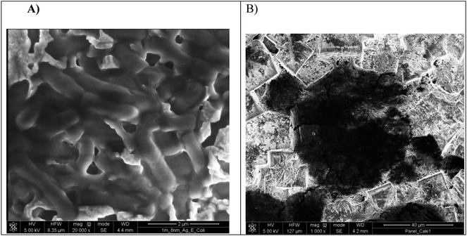
Moreover, the presence of cancer cells and pathogens onto the Ag-coated PV was examined by the SEM images and depicted in Fig. 8. The image in Fig. 8A shows E. coli cells, approximately 2–2.5 μm in diameter and the much bigger cell depicted in Fig. 8B reveals a Caki-1 cell, approximately 23–27 μm in diameter.
3.5. Uniformity of the SERS substrate
From the applications point of view, the reproducibility of SERS signals is one of the most important parameter. Fig. S8† presents the reproducibility of SERS spectra of p-ATP molecules (10−6 M) adsorbed onto four tested PV/Ag substrates. The SERS responses from the chosen 1m-type of PV/Ag devices for p-ATP molecules (10−6 M), B. subtilis, E. coli, and Caki-1 are depicted in Fig. 9. As can be seen, at each acquisition point the SERS spectra of p-ATP, cancer, and bacterial cells are enhanced very strongly with repeatable band intensity and position. To obtain the statistical data, the relative standard deviation (RSD) was estimated for the most intense marker bands (1078 cm−1 for p-ATP, 725 cm−1 for B. subtilis and E. coli, and 1452 cm−1 for Caki-1) and equals 4.5, 3.4, 2.8, and 3.1%, respectively. The reproducibility of the SERS signals recorded from different samples prepared using the same method was also tested. Fig. S9† presents the reproducibility of SERS signal for 10−6 M of p-ATP recorded from five separately prepared PV/SERS substrates. The achieved RSD was 6.4%, which clearly indicates that the prepared SERS substrate can be considered as a highly reproducible SERS platform. The achieved values are considered suitable for both qualitative and quantitative analysis94 and confirm that the designed PV/Ag fulfills all requirements for an ideal SERS-active substrate.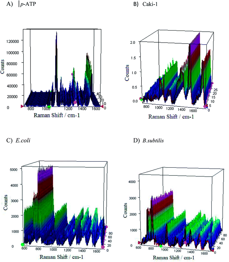 | ||
| Fig. 9 The representative SERS spectra of (A and B) p-ATP of concentration 10−6 M, (C) E. coli, and (D) B. subtilis recorded from 40 different spots on the SERS surface (type 1m) using mapping mode. | ||
3.6. Spectroelectrochemical analysis of p-aminothiophenol
It was highlighted in Chapter 3.2,† that p-aminothiophenol (p-ATP) is one of the most important molecules for SERS investigations. It adsorbs onto Ag and Au surfaces through a sulfur atom of the thiol group, and gives very strong SERS signals.62 Therefore it is widely used as a standard probe analyte for the investigation of SERS properties (enhancement factor (EF), reproducibility, and stability) for newly developed SERS substrates58,95–104 and as a model molecule for single molecule SERS studies.65,105,106On the other hand, as our developed substrate possesses built-in pathways for conducting the electrical current, it allows very efficient conjunction with electrochemistry to obtain the chemical and vibrational information in real-time.
Due to the presence of a CT (charge-transfer) SERS mechanism in p-ATP adsorbed onto Ag and Au substrates, p-ATP is an ideal molecule to study the contribution of EM (electrochemical) and CT to the total SERS enhancement.107–112 It is shown that spectral features of p-ATP originate from chemical (oxidative) transformation of p-ATP to 4,4′- dimercaptoazobenzene (DMAB, an azo compound) during SERS measurements.113
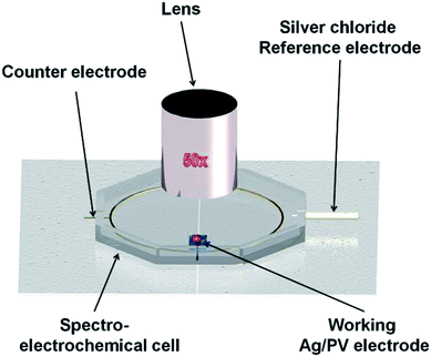
To illustrate the potential of our developed Ag/PV SERS substrate for spectroelectrochemical analysis, the electrochemical SERS spectra of p-ATP have been recoded.
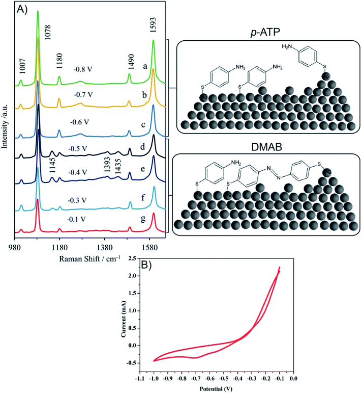
Fig. 10A presents the in situ SERS spectra of the SERS surface (working electrode) adsorbed onto Ag/PV in a 0.1 M NaClO4 aqueous solution. We have performed potential-depended SERS experiments in the potential region from −0.1 V to −1.0 V (see voltammogram presented in Fig. 10B). According to the CT mechanism, by changing the potential of the SERS-active metal surface, the intensity of some modes can be significantly enhanced by generation of resonance-like Raman scattering.62 As was depicted in Fig. 10A, at potential −0.5 V, the p-ATP started the transformation (oxidation) of p-ATP to 4,4′-dimercaptoazobenzene (DMAB), which is confirmed by the increasing of “b2-type” modes intensity.113 These bands appeared at 1145, 1393, and 1435 cm−1 and achieved the maximum intensity at −0.4 V. When the potential is moved to more negative values (see the range from – −0.6 V to −0.8 V) the recorded spectral features correspond to p-ATP with characteristic bands at 1078, 1180, 1490 and 1593 cm−1. These results correspond with the reduction peak observed on the presented voltammogram (Fig. 10B) at −0.7 V. The intensity of these “a1-type” modes is insensitive to the variation of electrode potential in comparison to the “b2-type” modes, which is similar to data presented in literature.62
To summarize, changes in the SERS spectra were observed by adjustment of the potential applied to a SERS-active platform. Our experimental results demonstrate the potential of our developed SERS-active substrate for in situ SERS spectroelectrochemical studies of intermediate species in a reacting system. Potential-dependent SERS studies can be extended to a wider range of analyzed molecules (e.g. metalloporphyrin, DNA, proteins) and a wider range of applications.
4. Conclusions
In this paper, we present a new type of SERS platform based on photovoltaic devices with high potential for SERS spectroelectrochemical measurements. This approach allows simultaneous electrochemical-characteristic and very sensitive vibrational investigation of electrochemical processes in real-time.The spectroscopic properties of fabricated SERS surfaces have been optimized in terms of PV arrays morphology, roughness, and thickness of the deposited metal. As a result, an easy, simple, and low-cost procedure for reproducible large scale fabrication of new conducive SERS substrates has been established. The applied PV material mainly consists of silicon and an anti-reflective layer of silicon nitride which gives the periodical structure. What is more, the PV cells used in the research described below were supplied as post-production residue; therefore, the total cost of this substrate is associated only with transport.
Our experimental results demonstrate that this SERS-active substrate with its strong surface-enhancement factor, high stability, and reproducibility can be used for detection of organic and biological species. For p-aminothiophenol the enhancement factor (EF) of the Raman signal on a Ag/PV surface 1m-type was estimated as high as 106. The SERS measurement reflects the excellent reproducibility of these substrates both across one single substrate and among substrates prepared in a repeatable procedure. In addition, the developed SERS substrate also allows the detection of cancer cells and bacterial pathogens as well as differentiation between Gram-positive and Gram-negative bacterial species in a label-free manner, based on their high-quality spectral features.
These results are promising for the extension of the SERS application range also into the study of the chemical reactions in the solid–liquid interface and/or controlling their dynamics.
Conflicts of interest
There are no conflicts to declare.Acknowledgements
Agnieszka Kamińska gives thanks for the financial support from Foundation for Polish Science under grant Team-Tech/2017-4/23 (POIR.04.04.00-00-4210/17-00). We would like to express special thanks to Bruk-Bet Solar for providing us with research materials and literature support that was necessary to perform this research. We would also like to thank Dr Wojciech Lisowski (ICP PAS, Warsaw) for XPS analysis.References
- J. J. Storhoff, R. Elghanian, R. C. Mucic, C. A. Mirkin and R. L. Letsinger, J. Am. Chem. Soc., 1998, 120, 1959 CrossRef CAS.
- Y. C. Cao, R. Jin and C. A. Mirkin, Science, 2002, 297, 1536 CrossRef CAS PubMed.
- D. Graham and K. Faulds, Chem. Soc. Rev., 2008, 37, 1042 RSC.
- R. Stevenson, K. Faulds and D. Graham, in Surface Enhanced Raman Spectroscopy, ed. S. Schlücker, Wiley-VCH Verlag GmbH & Co. KGaA, 2011, p. 241 Search PubMed.
- K. Faulds, F. McKenzie, W. E. Smith and D. Graham, Angew. Chem., Int. Ed. Engl., 2007, 46, 1829 CrossRef CAS PubMed.
- K. Faulds, W. E. Smith and D. Graham, Anal. Chem., 2004, 76, 412 CrossRef CAS PubMed.
- K. Faulds, W. E. Smith, D. Graham and R. J. Lacey, Analyst, 2002, 127, 282 RSC.
- E. Koglin and J.-M. Séquaris, Topics in Current Chemistry, Springer, Berlin, Heidelberg, 1986, vol. t34, pp. 1–57 Search PubMed.
- N. A. Abu Hatab, J. M. Oran and M. J. Sepaniak, ACS Nano, 2008, 2, 377 CrossRef CAS PubMed.
- R. Z. Tan, A. Agarwal, N. Balasubramanian, D. L. Kwong, Y. Jiang, E. Widjaja and M. Garland, Sens. Actuators, A, 2007, 139, 36 CrossRef CAS.
- A. Campion and P. Kambhampati, Chem. Soc. Rev., 1998, 27, 241 RSC.
- K. Kneipp, J. Phys. Chem. C, 2016, 120, 21076 CrossRef CAS.
- P. L. Stiles, J. A. Dieringer, N. C. Shah and R. P. Van Duyne, Annu. Rev. Anal. Chem., 2008, 1, 601 CrossRef CAS PubMed.
- J. P. Camden, J. A. Dieringer, Y. Wang, D. J. Masiello, L. D. Marks, G. C. Schatz and R. P. Van Duyne, J. Am. Chem. Soc., 2008, 130, 12616 CrossRef CAS PubMed.
- E. C. Le Ru and P. G. Etchegoin, Annu. Rev. Phys. Chem., 2012, 63, 65 CrossRef CAS PubMed.
- D. Bartczak and A. G. Kanaras, Langmuir, 2011, 27, 10119 CrossRef CAS.
- L. Ming, K. C. Scott, Z. Jianming, L. Jessica, P. A. Zoraida, M. Dongling and W. Nianqiang, Nanotechnology, 2012, 23, 115501 CrossRef PubMed.
- K. Gracie, M. Moores, W. E. Smith, K. Harding, M. Girolami, D. Graham and K. Faulds, Anal. Chem., 2016, 88, 1147 CrossRef CAS PubMed.
- A. Sivanesan, E. Witkowska, W. Adamkiewicz, L. Dziewit, A. Kaminska and J. Waluk, Analyst, 2014, 139, 1037 RSC.
- T. A. Alexander and D. M. Le, Appl. Opt., 2007, 46, 3878 CrossRef PubMed.
- I. R. Nabiev, H. Morjani and M. Manfait, Eur. Biophys. J., 1991, 19, 311 CrossRef CAS.
- H. Morjani, J. F. Riou, I. Nabiev, F. Lavelle and M. Manfait, Cancer Res., 1993, 53, 4784 CAS.
- H. H. Wang, C. Y. Liu, S. B. Wu, N. W. Liu, C. Y. Peng, T. H. Chan, C. F. Hsu, J. K. Wang and Y. L. Wang, Adv. Mater., 2006, 18, 491 CrossRef CAS.
- L. A. Dick, A. D. McFarland, C. L. Haynes and R. P. Van Duyne, J. Phys. Chem. B, 2002, 106, 853 CrossRef CAS.
- D. P. Fromm, A. Kinkhabwala, P. J. Schuck, W. E. Moerner, A. Sundaramurthy and G. S. Kino, J. Chem. Phys., 2006, 124, 61101 CrossRef PubMed.
- R. Alvarez-Puebla, B. Cui, J.-P. Bravo-Vasquez, T. Veres and H. Fenniri, J. Phys. Chem. C, 2007, 111, 6720 CrossRef CAS.
- D. J. Semin and K. L. Rowlen, Anal. Chem., 1994, 66, 4324 CrossRef CAS.
- A. Kaminska, E. Witkowska, A. Kowalska, A. Skoczynska, P. Ronkiewicz, T. Szymborski and J. Waluk, Anal. Methods, 2016, 8, 4521 RSC.
- A. Kamińska, M. Sprynskyy, K. Winkler and T. Szymborski, Anal. Bioanal. Chem., 2017, 409, 6337 CrossRef.
- A. Kaminska, K. Winkler, A. Kowalska, E. Witkowska, T. Szymborski, A. Janeczek and J. Waluk, Sci. Rep., 2017, 7, 10656 CrossRef.
- T. Szymborski, E. Witkowska, W. Adamkiewicz, J. Waluk and A. Kaminska, Analyst, 2014, 139, 5061 RSC.
- A. Kamińska, E. Witkowska, K. Winkler, I. Dzięcielewski, J. L. Weyher and J. Waluk, Biosens. Bioelectron., 2015, 66, 461 CrossRef PubMed.
- E. Witkowska, T. Szymborski, A. Kamińska and J. Waluk, Mater. Sci. Eng. C., 2017, 71, 345 CrossRef CAS PubMed.
- W. Shi, Y. Sahoo, M. T. Swihart and P. N. Prasad, Langmuir, 2005, 21, 1610 CrossRef CAS PubMed.
- K. Toshiaki, N. Kazuyuki and M. Hideki, Appl. Phys. Express, 2009, 2, 032001 CrossRef.
- K. Ikeda, S. Suzuki and K. Uosaki, Nano Lett., 2011, 11, 1716 CrossRef CAS PubMed.
- H. Liu, L. Zhang, X. Lang, Y. Yamaguchi, H. Iwasaki, Y. Inouye, Q. Xue and M. Chen, Sci. Rep., 2011, 1, 112 CrossRef PubMed.
- R. Bhardwaj, X. Fang, P. Somasundaran and D. Attinger, Langmuir, 2010, 26, 7833 CrossRef CAS PubMed.
- T. Ryo, F. Takao, U. Yuichi and Y. Akinobu, Jpn. J. Appl. Phys., 2013, 52, 06GK12 CrossRef.
- R. Hara, T. Fukuoka, R. Takahashi, Y. Utsumi and A. Yamaguchi, RSC Adv., 2015, 5, 1378 RSC.
- M. Chirumamilla, A. Toma, A. Gopalakrishnan, G. Das, R. P. Zaccaria, R. Krahne, E. Rondanina, M. Leoncini, C. Liberale, F. D. Angelis and E. D. Fabrizio, Adv. Mater., 2014, 26, 2353 CrossRef CAS PubMed.
- Z. Wang, Z. Feng, L. Lin, P. Huang and Z. Zheng, Appl. Surf. Sci., 2015, 356, 1314 CrossRef CAS.
- H. Luo, Y. Huang, K. Lai, B. A. Rasco and Y. Fan, Food Control, 2016, 68, 229 CrossRef CAS.
- W. Wang, Y. Yan, N. Zhou, H. Zhang, D. Li and D. Yang, Nanoscale, 2016, 8, 3704 RSC.
- M. Nguyen, A. Kanaev, X. Sun, E. Lacaze, S. Lau-Truong, A. Lamouri, J. Aubard, N. Felidj and C. Mangeney, Langmuir, 2015, 31, 12830 CrossRef CAS PubMed.
- I. C. G. Thanos, J. Electroanal. Chem. Interfacial Electrochem., 1986, 200, 231 CrossRef CAS.
- D.-Y. Wu, J.-F. Li, B. Ren and Z.-Q. Tian, Chem. Soc. Rev., 2008, 37, 1025 RSC.
- T. Itoh, T. Maeda and A. Kasuya, Faraday Discuss., 2006, 132, 95 RSC.
- K. S. Joya and H. J. M. Groot, J. Raman Spectrosc., 2013, 44, 1195 CrossRef CAS.
- S. Hy, F. Felix, Y.-H. Chen, J.-y Liu, J. Rick and B.-J. Hwang, J. Power Sources, 2014, 256, 324 CrossRef CAS.
- M. Meneghello, E. Papadopoulou, P. Ugo and P. N. Bartlett, Electrochim. Acta, 2016, 187, 684 CrossRef CAS.
- S. Mahajan, J. Richardson, T. Brown and P. N. Bartlett, J. Am. Chem. Soc., 2008, 130, 15589 CrossRef CAS.
- R. W. Miles, Vacuum, 2006, 80, 1090 CrossRef CAS.
- A. Trügler, J.-C. Tinguely, G. Jakopic, U. Hohenester, J. R. Krenn and A. Hohenau, Phys. Rev. B: Condens. Matter Mater. Phys., 2014, 89, 165409 CrossRef.
- Y. Zhao, X. Liu, D. Y. Lei and Y. Chai, Nanoscale, 2014, 6, 1311 RSC.
- A. Matikainen, T. Nuutinen, T. Itkonen, S. Heinilehto, J. Puustinen, J. Hiltunen, J. Lappalainen, P. Karioja and P. Vahimaa, Sci. Rep., 2016, 6, 37192 CrossRef CAS PubMed.
- Y. Song, P. J. Swedlund, G. J. McIntosh, B. C. Cowie, G. I. Waterhouse and J. B. Metson, Langmuir, 2012, 28, 16890 CrossRef CAS PubMed.
- Y. F. Huang, H. P. Zhu, G. K. Liu, D. Y. Wu, B. Ren and Z. Q. Tian, J. Am. Chem. Soc., 2010, 132, 9244 CrossRef CAS.
- K. Kim, K. L. Kim, J. Y. Choi, D. Shin and K. S. Shin, Phys. Chem. Chem. Phys., 2011, 13, 15603 RSC.
- W. Hill and B. Wehling, J. Phys. Chem., 1993, 97, 9451 CrossRef CAS.
- M. Dendisová-Vyškovská, V. Prokopec, M. Člupek and P. Matějka, J. Raman Spectrosc., 2012, 43, 181 CrossRef.
- M. Osawa, N. Matsuda, K. Yoshii and I. Uchida, J. Phys. Chem., 1994, 98, 12702 CrossRef CAS.
- K. Kim, D. Shin, J.-Y. Choi, K. L. Kim and K. S. Shin, J. Phys. Chem. C, 2011, 115, 24960 CrossRef CAS.
- A. Martín, A. Pescaglini, C. Schopf, V. Scardaci, R. Coull, L. Byrne and D. Iacopino, J. Phys. Chem. C, 2014, 118, 13260 CrossRef.
- J. R. Lombardi and R. L. Birke, J. Phys. Chem. C, 2008, 112, 5605 CrossRef CAS.
- X. Hu, T. Wang, L. Wang and S. Dong, J. Phys. Chem. C, 2007, 111, 6962 CrossRef CAS.
- M. Moskovits and J. S. Suh, J. Phys. Chem., 1984, 88, 5526 CrossRef CAS.
- A. Kamińska, T. Szymborski, T. Jaroch, A. Zmysłowski and A. Szterk, Mater. Sci. Eng. C., 2018, 84, 208 CrossRef.
- J. Tang, F. S. Ou, H. P. Kuo, M. Hu, W. F. Stickle, Z. Li and R. S. Williams, Appl. Phys. A: Mater. Sci. Process., 2009, 96, 793 CrossRef CAS.
- M. S. Schmidt, A. Boisen and J. Hübner, IEEE, 2009, p. 1763 Search PubMed.
- Y. S. Hu, J. Jeon, T. J. Seok, S. Lee, J. H. Hafner, R. A. Drezek and H. Choo, ACS Nano, 2010, 4, 5721 CrossRef CAS PubMed.
- T. Luna-Pineda, K. Soto-Feliciano, E. De La Cruz-Montoya, L. C. Pacheco Londoño, C. Ríos-Velázquez and S. P. Hernández-Rivera, Spectroscopic characterization of biological agents using FTIR, normal Raman and surface-enhanced Raman spectroscopies, in Chemical and Biological Sensing VIII, ed. A. W. Fountain III, Proceedings of the SPIE 6554, Orlando, FL, USA, 2007, p. 65540K Search PubMed.
- W. F. Pearman, M. Lawrence-Snyder, S. M. Angel and A. W. Decho, Appl. Spectrosc., 2007, 61, 1295 CrossRef CAS PubMed.
- J. Guicheteau, L. Argue, D. Emge, A. Hyre, M. Jacobson and S. Christesen, Appl. Spectrosc., 2008, 62, 267 CrossRef CAS PubMed.
- Y. Chao and T. Zhang, Anal. Bioanal. Chem., 2012, 404, 1465 CrossRef CAS PubMed.
- P. Kubryk, R. Niessner and N. P. Ivleva, Analyst, 2016, 141, 2874 RSC.
- F. Madzharova, Z. Heiner, M. Gühlke and J. Kneipp, J. Phys. Chem. C, 2016, 120, 15415 CrossRef CAS PubMed.
- Z. Movasaghi, S. Rehman and I. U. Rehman, Appl. Spectrosc. Rev., 2007, 42, 493 CrossRef CAS.
- M. L. Laucks, A. Sengupta, K. Junge, E. J. Davis and B. D. Swanson, Appl. Spectrosc., 2005, 59, 1222 CrossRef CAS PubMed.
- C. Krafft, L. Neudert, T. Simat and R. Salzer, Spectrochim. Acta, Part A, 2005, 61, 1529 CrossRef PubMed.
- R. K. Dukor, in Handbook of Vibrational Spectroscopy, John Wiley & Sons, Ltd, 2006 Search PubMed.
- A. Walter, A. Marz, W. Schumacher, P. Rosch and J. Popp, Lab Chip, 2011, 11, 1013 RSC.
- M. C. Demirel, P. Kao, N. Malvadkar, H. Wang, X. Gong, M. Poss and D. L. Allara, Biointerphases, 2009, 4, 35 CrossRef CAS PubMed.
- L. Noorani, M. Stenzel, R. Liang, M. H. Pourgholami and D. L. Morris, J. Nanobiotechnol., 2015, 13, 25 CrossRef PubMed.
- W. T. Cheng, M. T. Liu, H. N. Liu and S. Y. Lin, Microsc. Res. Tech., 2005, 68, 75 CrossRef CAS PubMed.
- U. Neugebauer, J. H. Clement, T. Bocklitz, C. Krafft and J. Popp, J. Biophotonics, 2010, 3, 579 CrossRef CAS.
- N. Stone, C. Kendall, J. Smith, P. Crow and H. Barr, Faraday Discuss., 2004, 126, 141 RSC.
- I. Notingher, C. Green, C. Dyer, E. Perkins, N. Hopkins, C. Lindsay and L. L. Hench, J. R. Soc., Interface, 2004, 1, 79 CrossRef CAS.
- M. F. K. Fung, M. K. Senterman, N. Z. Mikhael, S. Lacelle and P. T. T. Wong, Biospectroscopy, 1996, 2, 155 CrossRef CAS.
- N. Stone, C. Kendall, N. Shepherd, P. Crow and H. Barr, J. Raman Spectrosc., 2002, 33, 564 CrossRef CAS.
- Z. Huang, A. McWilliams, H. Lui, D. I. McLean, S. Lam and H. Zeng, Int. J. Cancer, 2003, 107, 1047 CrossRef CAS.
- U. Utzinger, D. L. Heintzelman, A. Mahadevan-Jansen, A. Malpica, M. Follen and R. Richards-Kortum, Appl. Spectrosc., 2001, 55, 955 CrossRef CAS.
- C. Krafft, T. Knetschke, A. Siegner, R. H. W. Funk and R. Salzer, Vib. Spectrosc., 2003, 32, 75 CrossRef CAS.
- L. L. Qu, D. W. Li, J. Q. Xue, W. L. Zhai, J. S. Fossey and Y. T. Long, Lab Chip, 2012, 12, 876 RSC.
- S. Guo and E. Wang, J. Colloid Interface Sci., 2007, 315, 795 CrossRef CAS PubMed.
- S. Guo, L. Wang and E. Wang, Chem. Commun., 2007, 3163 RSC.
- L. Shang, Y. Wang, L. Huang and S. Dong, Langmuir, 2007, 23, 7738 CrossRef CAS.
- Y. Bae, N. H. Kim, M. Kim, K. Y. Lee and S. W. Han, J. Am. Chem. Soc., 2008, 130, 5432 CrossRef CAS.
- Y. M. Lee, K. Kim and K. S. Shin, J. Phys. Chem. C, 2008, 112, 10715 CrossRef CAS.
- B. Yan, A. Thubagere, W. R. Premasiri, L. D. Ziegler, L. Dal Negro and B. M. Reinhard, ACS Nano, 2009, 3, 1190 CrossRef CAS.
- G. Merga, N. Saucedo, L. C. Cass, J. Puthussery and D. Meisel, J. Phys. Chem. C, 2010, 114, 14811 CrossRef CAS.
- J. Theiss, P. Pavaskar, P. M. Echternach, R. E. Muller and S. B. Cronin, Nano Lett., 2010, 10, 2749 CrossRef CAS.
- D.-Y. Wu, X.-M. Liu, Y.-F. Huang, B. Ren, X. Xu and Z.-Q. Tian, J. Phys. Chem. C, 2009, 113, 18212 CrossRef CAS.
- D.-Y. Wu, L.-B. Zhao, X.-M. Liu, R. Huang, Y.-F. Huang, B. Ren and Z.-Q. Tian, Chem. Commun., 2011, 47, 2520 RSC.
- G. H. Gu and J. S. Suh, J. Phys. Chem. A, 2009, 113, 8529 CrossRef CAS.
- W.-H. Park and Z. H. Kim, Nano Lett., 2010, 10, 4040 CrossRef CAS PubMed.
- D. P. Fromm, A. Sundaramurthy, A. Kinkhabwala, P. J. Schuck, G. S. Kino and W. E. Moerner, J. Chem. Phys., 2006, 124, 061101 CrossRef.
- J. W. Gibson and B. R. Johnson, J. Chem. Phys., 2006, 124, 064701 CrossRef.
- F. Jäckel, A. A. Kinkhabwala and W. E. Moerner, Chem. Phys. Lett., 2007, 446, 339 CrossRef.
- C. Chenal, R. L. Birke and J. R. Lombardi, ChemPhysChem, 2008, 9, 1617 CrossRef CAS.
- M. Sun and H. Xu, ChemPhysChem, 2009, 10, 392 CrossRef CAS PubMed.
- J. H. Yoon, J. S. Park and S. Yoon, Langmuir, 2009, 25, 12475 CrossRef CAS.
- Y.-F. Huang, D.-Y. Wu, H.-P. Zhu, L.-B. Zhao, G.-K. Liu, B. Ren and Z.-Q. Tian, PCCP, 2012, 14, 8485 RSC.
Footnote |
| † Electronic supplementary information (ESI) available. See DOI: 10.1039/c8ra08319c |
| This journal is © The Royal Society of Chemistry 2019 |

