 Open Access Article
Interconnected electrocatalytic Pt-metal networks by plasma treatment of nanoparticle-peptide fibril assemblies
J. Bandaka,
J. Petzolda,
H. Hataheta,
A. Pragera,
B. Kersting b,
Ch. Elsnera and
B. Abel
 *ac
*ac
aLeibniz Institute of Surface Engineering (IOM), Department Functional Surfaces, Permoserstr. 15, D-04318 Leipzig, Germany. E-mail: bernd.abel@iom-leipzig.de
bInstitute of Inorganic Chemistry, University Leipzig, Johannisallee 29, D-04103 Leipzig, Germany
cWilhelm-Ostwald-Institute of Physical and Theoretical Chemistry, University Leipzig, Linnéstrasse 2, D-04103 Leipzig, Germany
First published on 13th February 2019
Abstract
Noble metal catalysts possess outstanding catalytic behaviors in organic reactions, photocatalysis, electrocatalysis and many other applications. Peptide fibrils are used for the controllable nanostructuring of metal nanoparticles with specific sizes, shapes and high-surface area structures. The degradation of these fibrils with O2-plasma yields interconnected networks of nanoparticles, similar to metallic nanowires. Herein, platinum nanoparticles (Pt-NPs) were synthesized by reduction using VUV excimer radiation. The particle size was characterized by dynamic light scattering (DLS). Due to agglomeration, the metal nanoparticles were stabilized using poly(vinyl pyrrolidone) (PVP) and the same synthesis procedure. The influence of the polymer PVP molecular weight (Mwt), PVP concentration (Cp) and VUV irradiation time on platinum nanoparticle size was investigated. Small (2–3 nm) Pt-NPs are formed in the case of PVP with Mwt = 10![[thin space (1/6-em)]](https://www.rsc.org/images/entities/char_2009.gif) 000 g mol−1. With increasing PVP Mwt, decreasing PVP concentration and shorter irradiation times, larger sized nanoparticles appear. The applicability of templated platinum nanoparticles, both the PVP-stabilized and non-stabilized Pt-NPs, immobilized via electrostatic interactions on the solid phase-synthesized aniline-GGAAKLVFF (AFP) peptide fibrils was investigated to serve as possible electrode material. The plasma treatment of the nanoparticle-fibril-assemblies was also studied as a novel technique. The Pt-NPs-AFP fibrils and the PVP-stabilized-Pt-NPs-AFP fibrils nanohybrids were employed to modify electrodes and then subjected to O2-plasma treatment. These O2-plasma treated/modified electrodes exhibited high electrocatalytic activities towards oxygen reduction in cyclic voltammetry measurements. Thus, the aforementioned nanocomposites hold great potential for polymer electrolyte fuel cells and other electrochemical applications in miniature devices and microfluidic chips.
000 g mol−1. With increasing PVP Mwt, decreasing PVP concentration and shorter irradiation times, larger sized nanoparticles appear. The applicability of templated platinum nanoparticles, both the PVP-stabilized and non-stabilized Pt-NPs, immobilized via electrostatic interactions on the solid phase-synthesized aniline-GGAAKLVFF (AFP) peptide fibrils was investigated to serve as possible electrode material. The plasma treatment of the nanoparticle-fibril-assemblies was also studied as a novel technique. The Pt-NPs-AFP fibrils and the PVP-stabilized-Pt-NPs-AFP fibrils nanohybrids were employed to modify electrodes and then subjected to O2-plasma treatment. These O2-plasma treated/modified electrodes exhibited high electrocatalytic activities towards oxygen reduction in cyclic voltammetry measurements. Thus, the aforementioned nanocomposites hold great potential for polymer electrolyte fuel cells and other electrochemical applications in miniature devices and microfluidic chips.
Introduction
Transition metal nanoparticles have generated a growing interest in the last decades due to their potential applications in catalysis,1,2 nanoelectronics,3 optoelectronics,4 sensors and magnetic5 or other advanced materials.6–8 Successful use of metal nanoparticles in various applications depends on their quantum size effect,9–12 which is a consequence of the increased confinement of the movement of electrons in nanoparticles, as evidenced by the size-dependent catalytic, optical, electronic and magnetic properties. These nanoparticles also often agglomerate to minimize the total surface energy of the system. Thus, it is imperative to control the nanoparticle size and stabilize it against irreversible aggregation.Platinum nanoparticles (Pt-NPs) are of particular interest since they are used extensively as catalyst-electrode coatings, for example in the electro-oxidation of alcohols in fuel cell technology.13,14 Pt-NPs have also been used as sensors,15 electronic devices,16 fillers and active components in composite materials,17 and other applications. Therefore, it is crucial to stabilize the developed nanoparticles with a well-controlled mean size in order to prevent their aggregation, which reduces the specific surface area and the interfacial free energy, and by this means lessens the nanoparticles' reactivity.18 Various stabilizing agents have been used as capping agents for stabilizing nanoparticles, including polymers such as poly(vinyl alcohol) (PVA)19 and poly(vinyl pyrrolidone) (PVP),20,21 ligands such as sodium citrate,22 and surfactants such as tetraalkylammonium halides.23,24 It is well-acknowledged that the type of stabilizer that is used affects the nanoparticles' stability and therefore their catalytic activity.25,26
Different methods have been developed for the synthesis of transition metal nanoparticles, including microemulsion,27 sonochemical,28 polyol,29 solvent reduction,30 reverse micelle,31 and ionic liquid,32 among other methods. However, metal nanoparticles synthesized by reduction using VUV-excimer radiation represents one of the most interesting techniques in terms of safety, controlling the synthetic parameters, cost and potential for high volume production as opposed to other radiation based ionization techniques. The radiolytic generation of elemental metal nanoparticles via metal ion reduction is based on the investigation of Kurihara et al.33 Chemical bond dissociation, ionization and radical formation are the most prominent results of high-energy photon interaction with molecules besides excitation.
Amyloid peptides readily self-assemble into fibrils in aqueous solutions and platinum nanoparticles (Pt-NPs) can be immobilized onto their surface via electrostatic interaction.34 Compared to other currently available techniques for the fabrication of metal-peptide fibrils, the noncovalent functionalization strategy is able to deposit nanoparticles on peptide fibrils with a network-like distribution and high metal loading, which is important for applications in catalysis, electronic materials and other corresponding fields. Zhou et al.34 managed to immobilize negatively charged Pt-NPs onto the positively charged AFP (aniline-GGAAKLVFF) fibrils, such that the morphology and dispersion of Pt-NPs were strictly controlled and the catalytic performance was improved consequently for the oxygen reduction reaction. However, the peptide fibrils were not removed and had a certain influence on the cyclic voltammetry measurement. To eliminate the influence of the fibrils, plasma treatment of the nanoparticles-fibrils-assemblies was investigated in this work.
The aim of this investigation is to study the influence of synthesis conditions of Pt-NPs, in the presence of the stabilizing agent PVP, on the particle size based on a novel, simple, cost effective and environmentally friendly manufacturing process of the Pt-NPs via VUV excimer lamp irradiation. In addition, the objective includes the investigation of the feasibility of the deposition of metal nanoparticles as a porous net-like structure on peptide fibrils, as well as O2-plasma treatment of the nanoparticle-fibril construct (Scheme 1).
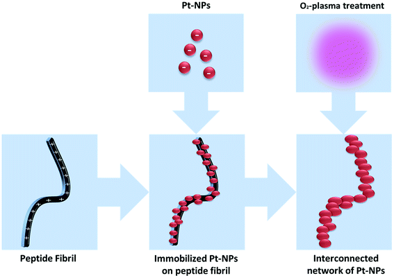 | ||
| Scheme 1 Preparation of an interconnected network of Pt-NPs via self-assembled peptide fibrils and after O2-plasma treatment. | ||
Methods section
Reagents
Chemicals were ordered from commercial sources as follows: Fmoc-Phe-Wang, Fmoc-Phe-OH, Fmoc-Val-OH, Fmoc-Leu-OH, Fmoc-Lys(Boc)-OH, Fmoc-Ala-OH, Fmoc-Gly-OH, 4-aminophenylacetic acid, DMF, DCM, TIPS, piperidine (Sigma Aldrich, Germany); chloroplatinic acid (8 wt% in water), HOBT, TBTU, diethyl ether (Fluka, Buchs, Switzerland); 2-propanol, DMSO (VWR, Leuven, Netherlands); TFA (Merck, KGaA, Darmstadt, Germany); DIEA (Roth, Karlsruhe, Germany); water (Millipore grade) (laboratory purification system).Peptide synthesis
AFP (aniline-GGAAKLVFF) was synthesized by microwave-assisted solid-phase peptide synthesis using the Fmoc strategy on a semi-automatic peptide synthesizer (Biotage, Uppsala, Sweden). Briefly, Fmoc-protected amino acids (2.9 eq.) were coupled by TBTU/HOBT (3 eq.) in DMF, and the Fmoc group was then removed using 20% piperidine in DMF. Finally, the peptide was cleaved from the resin using TFA![[thin space (1/6-em)]](https://www.rsc.org/images/entities/char_2009.gif) :
:![[thin space (1/6-em)]](https://www.rsc.org/images/entities/char_2009.gif) TIPS
TIPS![[thin space (1/6-em)]](https://www.rsc.org/images/entities/char_2009.gif) :
:![[thin space (1/6-em)]](https://www.rsc.org/images/entities/char_2009.gif) water 95/2.5/2.5 (v/v/v) and precipitated after solvent evaporation in ice cold diethyl ether. The peptide was used without further HPLC purification due to the immediate formation of fibrils in aqueous systems and HPLC system clogging. For purification purposes, fibrils were formed in aqueous solutions and then precipitated by centrifugation. The supernatant liquid was discarded and the precipitated fibrils were dissolved in hexafluoroisopropanol (HFIP). After evaporation of the solvent, lyophilization of the remonomerized peptide occurred. The peptide was analyzed by MALDI-TOF-MS.
water 95/2.5/2.5 (v/v/v) and precipitated after solvent evaporation in ice cold diethyl ether. The peptide was used without further HPLC purification due to the immediate formation of fibrils in aqueous systems and HPLC system clogging. For purification purposes, fibrils were formed in aqueous solutions and then precipitated by centrifugation. The supernatant liquid was discarded and the precipitated fibrils were dissolved in hexafluoroisopropanol (HFIP). After evaporation of the solvent, lyophilization of the remonomerized peptide occurred. The peptide was analyzed by MALDI-TOF-MS.
Fibrillation assays
Fibrillation of the lyophilized AFP peptide was induced by dissolving the peptide in DMSO at a concentration of 1 mg peptide/10 μl DMSO. Then, fibril formation was prompted by diluting the sample with Millipore water to achieve a final concentration of the peptide of 1 mg ml−1. The sample was then shaken at 200 rpm and 25 °C during fibril formation.Platinum nanoparticle synthesis
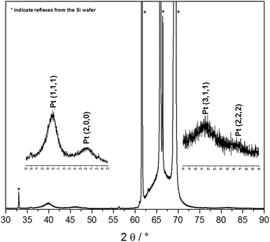
The synthesis of Pt-NPs is based on the reduction of chloroplatinic acid (H2PtCl6) via VUV excimer lamp irradiation in the presence of 2-propanol radicals. Briefly, the procedure is as follows: a precursor solution of H2PtCl6 (8 wt% in water), Millipore water and 2-propanol was prepared, and then sonicated for 15 min. Depending on the low photon penetration depth into the material, only 50 μl of the precursor solution were distributed into the 96 wells of a microtiter plate, and then irradiated via a VUV excimer lamp (λ = 172 nm, Power: 100%) for 5 min. Spherical nanoparticles were obtained with different diameters depending on the concentration of H2PtCl6 used. The production of the Pt-NPs was confirmed by XRD, as in Fig. 1.Stabilized-platinum nanoparticle synthesis
Stabilized Pt-NPs were prepared by reducing H2PtCl6 with 2-propanol and VUV excimer lamp irradiation (172 nm) in the presence of the stabilizing agent PVP (see platinum nanoparticle synthesis above). Polymer molecular weight (Mwt), polymer concentration (Cp) and VUV irradiation time were varied, and their influence on the nanoparticle size studied.Immobilization of Pt-NPs on the peptide fibrils
Both the Pt-NPs and the PVP-stabilized Pt-NPs were incubated with the AFP fibril solution (see above) in a 1![[thin space (1/6-em)]](https://www.rsc.org/images/entities/char_2009.gif) :
:![[thin space (1/6-em)]](https://www.rsc.org/images/entities/char_2009.gif) 1 (v/v) ratio for 24 h at 25 °C with shaking at 200 rpm. The mixing ratio was used to immobilize as many Pt-NPs as possible on the surface of the peptide fibrils.
1 (v/v) ratio for 24 h at 25 °C with shaking at 200 rpm. The mixing ratio was used to immobilize as many Pt-NPs as possible on the surface of the peptide fibrils.
O2-plasma cleaning
After the irreversible immobilization of the Pt-NPs on the surface of the AFP peptide fibrils was complete, the nanoparticles-fibrils-assemblies were subjected to O2-plasma treatment for 5 min at P = 300 W (Europlasma®, Junior Advanced) and 168 mTorr to remove the peptide fibrils and the PVP present when the PVP-stabilized Pt-NPs were employed, and finally obtain Pt-NPs in a network-like structure.Scanning electron microscopy
Structure and morphology of nanoparticles and peptide aggregates were studied using an Ultra 55 SEM (Carl Zeiss Ltd., Göttingen, Germany). All samples were immobilized on silicon wafers (Plano, agar scientific, #G3390, Germany) by dry droplet method and investigated without prior metal coating.Zeta potential and DLS measurements
The ζ-potential was determined via electrophoretic light scattering (ELS) at λ = 633 nm with a Malvern® (Zetasizer Nano ZSP) instrument, using 1 ml of the platinum nanoparticle dispersion (pH between 2.55 and 3.18) or of the PVP-stabilized one (pH between 2.56 and 2.87). Typically, 1 mg ml−1 of the peptide (AFP) has been dissolved in DMSO (1%) and then fibrillated with the addition of 990 μl water. The solution was finally incubated for 24 h on a shaking plate at 25 °C and 200 rpm, and then measured in three ζ-potential scans at a pH = 2.58. The Malvern® (Zetasizer Nano ZSP) instrument was also used to determine the particle size, using also 1 ml of the various platinum nanoparticle suspensions, whether they are PVP-stabilized or not. The suspension is inserted into the device and allowed to temper for 2 min at 25 °C. Parameters: scattering angle = 173°, measurement duration = 300 min.Atomic force microscopy
The AFM samples were prepared by dry droplet method of 1 μl of sample solutions on silicon wafers (Plano, agar scientific, #G3390, Germany). Morphological analysis was carried out with a Bruker Dimension Icon atomic force microscope (Bruker, Karlsruhe, Germany) in tapping mode, in air, under the following conditions: scan rate 0.50 Hz, OTESPA-R3 aluminum sputtered silicon probes (Bruker, Karlsruhe, Germany) with tip apex radius of 10 nm, resonant frequency range of AFM cantilever 200–400 Hz, and number of pixels 512 × 512. Representative images were obtained by scanning different samples at five or more randomly selected positions over the entire template. The resulting images were processed off-line with Gwyddion 2.49 software (http://gwyddion.net) by applying a flattening algorithm to remove the background slope.X-ray photoelectron spectroscopy
The chemical surface composition of nanoparticle-fibril-assemblies before and after being subjected to O2-plasma treatment was determined on a Kratos AXIS Ultra Spectrometer (Kratos Analytical Ltd., Manchester; UK) equipped with a monochromatic Al Kα excitation source and was operated at 150 W (15 kV, 10 mA). Binding energies were corrected by referring them to the C (1s) signal at a binding energy of 285.0 eV.Cyclic voltammetry
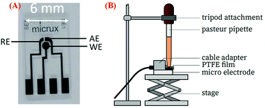
A three-electrode system (ED-SE1-Pt), which was purchased from Micrux Technologies (Ovideo, Spain), was used in this study.35 The system consists of three electrodes – a circular working Pt electrode (WE) with 1 mm diameter, a Pt reference electrode (RE), and an auxiliary Pt electrode (AE). Before any modification of electrodes, they were electrochemically cleaned by scanning 10 cycles of cyclic voltammetry (CV) in the ± 1.5 V range at 100 mV s−1 in 0.1 M KCL solution. A volume of 5 μl of the Pt-NPs-AFP fibrils and the PVP-stabilized Pt-NPs-AFP fibrils nanocomposites (see immobilization of Pt-NPs on the peptide fibrils) were dispersed on the WE and dried in air. Duplicate samples of the modified electrodes were prepared and then subjected to O2-plasma treatment for 5 min at P = 300 W (Europlasma®, Junior Advanced) and 168 mTorr to degrade the peptide fibrils and the PVP present. A multichannel potentiostat (VSP 300, Bio-logic Science Instruments, France) was used for all electrochemical measurements. The electrode system was inserted into the adapter (ED-DROP-CELL, Micrux Fluidic) and connected to the potentiostat. A Pasteur pipette, containing the electrolyte solution, is mounted on a tripod attachment and positioned directly above the electrode system connecting all the electrodes. A polytetrafluoroethylene (PTFE) film is used to seal the connection. CV was performed in O2-saturated 0.1 M H2SO4 solution at a scan rate of 50 mV s−1 ranging from −0.65 to 0.05 V.Results and discussion
Synthesis of platinum nanoparticles
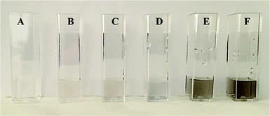
VUV-irradiation of aqueous precursor solutions was used for the synthesis of the platinum nanoparticles (Pt-NPs), which is a method that has already been used successfully for the preparation of gold nanoparticles (Au-NPs).36 172 nm photons from excimers are utilized for the production of the nanoparticles. Via this method, the density of the nanoparticles is controlled by the concentration of the precursor H2PtCl6. The fabrication of the Pt-NPs was evidenced by a color change (colorless to black or dark brown) observable after the 5 min irradiation of the Pt precursor solution by the VUV excimer lamp (Fig. 2). The black or dark brown color became more intense with the increase of the concentration of H2PtCl6 used. The influence of the precursor H2PtCl6 concentration on the platinum nanoparticle size and ζ-potential was studied using the Malvern® (Zetasizer Nano ZSP) instrument. The results are shown in (Table 1). The shape of the particles was assumed to be spherical).
| Suspension number | H2PtCl6 [μl] | H2O [μl] | C3H8O [μl] | ζ-Potential [mV] | ∅ sizea [nm] | ||
|---|---|---|---|---|---|---|---|
| 5 min irradiation time | 5 min irradiation time | ||||||
| a Apparent size of particles may indicate aggregates. | |||||||
| Pt-NPs #1 | 4 | 2400 | 200 | −2 ± 10 | 249 (78%) | 1167 (21%) | 4333 (1%) |
| Pt-NPs #2 | 8 | 6000 | 400 | −17 ± 6 | 222 (81%) | 1024 (19%) | — |
| Pt-NPs #3 | 4 | 6000 | 400 | −21 ± 7 | 71 (32%) | 546 (68%) | — |
| Pt-NPs #4 | 4 | 9600 | 600 | −28 ± 11 | 32 (32%) | 65 (68%) | — |
| Pt-NPs #5 | 4 | 13![[thin space (1/6-em)]](https://www.rsc.org/images/entities/char_2009.gif) 200 200 |
800 | −32 ± 11 | 19 (100%) | — | — |
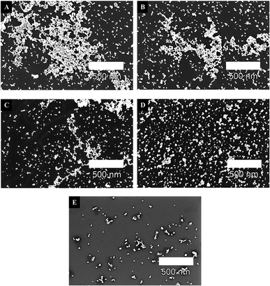
It is shown that the precursor (H2PtCl6) concentration remarkably influences the size and structure of platinum nanoparticles. The size distribution indicates an increase in the agglomeration of the resulting nanoparticles with the increase of the H2PtCl6 concentration, as can also be shown in the scanning electron microscope (SEM) images in Fig. 3.
The zeta potential (ζ-potential) is an indicator of the stability of particles. In pure aqueous solutions, the overlap between the diffuse double layers of two approaching particles results in a repulsive double layer interaction potential, which leads to particle stabilization.37–39 Thusly, particles without or with low surface charges, i.e. low ζ-potentials, start to agglomerate by van der Waals forces.40 It was observed that a zeta potential of |30| mV decreases the probability for agglomeration of the Pt-NPs in an aqueous solution by electrostatic repulsion (Scheme 2).
The values in Table 1 and the SEM images in Fig. 3 show particles in the fast aggregation regime, where they start aggregating immediately after irradiation. Pt-NPs #5 suspension (4 μl/14![[thin space (1/6-em)]](https://www.rsc.org/images/entities/char_2009.gif) 000 μl solution) displays minimal size of the Pt-NPs, with a constant single nanoparticle size of ∅ = 19 nm. This suspension also contains the lowest precursor concentration (4 μl/14
000 μl solution) displays minimal size of the Pt-NPs, with a constant single nanoparticle size of ∅ = 19 nm. This suspension also contains the lowest precursor concentration (4 μl/14![[thin space (1/6-em)]](https://www.rsc.org/images/entities/char_2009.gif) 000 μl solution), and therefore a high ζ-potential of −32 mV, which indicates the stability and improbability of its Pt-NPs to agglomerate. A low precursor concentration and thus larger distances between the nanoparticles leads to a minimization of the van der Waals attraction forces between the particles, which slow their aggregation.41,42
000 μl solution), and therefore a high ζ-potential of −32 mV, which indicates the stability and improbability of its Pt-NPs to agglomerate. A low precursor concentration and thus larger distances between the nanoparticles leads to a minimization of the van der Waals attraction forces between the particles, which slow their aggregation.41,42
The VUV irradiation time displayed in (Table 2) has important effects on the particle size and its ζ-potential, but does not show a specific trend. Short irradiation times of 0.5 and 1 min exhibit Pt-NPs with positive zeta potentials of 12 and 13 mV, respectively. These nanoparticles also demonstrate a high propensity to agglomerate as depicted by their large particle sizes. VUV irradiation time of 2 min shows the smallest size of Pt-NPs (∼57 nm). This suspension has the highest ζ-potential of −23 mV, which reduces the nanoparticles' proclivity to agglomerate. After 2 min, the increase of the irradiation time to 3 and 5 min causes the decrease of the ζ-potential, thusly increasing the agglomeration of the particles and their apparent average sizes. It is also worth mentioning that the color intensity of the nanoparticle suspensions (black or dark brown) increases when the VUV irradiation time was increased from 0.5 min to 5 min.
Immobilization of Pt-NPs on peptide fibrils
Amyloid fibrils are generally formed through the generation of β-sheets, which run perpendicular to the fibril axis, by hydrogen bonding. The formation of a steric zipper is then achieved from the interlocking of two sheets with each other. Finally, these pairs of sheets interact to form fibrils.43,44 As such, the AFP (aniline-GGAAKLVFF) self assembles into positively charged fibrils. Fig. 4A shows the AFM image of the AFP fibrils, where it is obvious that these fibrils tend to aggregate in a net-like formation, with a diameter of about 1–5 nm and a length of 200 nm to several micrometers acquired from AFM measurements.34 The ζ-potential of the synthesized AFP fibrils was measured to be 34.0 mV at pH = 2.58. Hence, the AFP fibrils are positively charged and can readily immobilize the negatively charged Pt-NPs onto their surfaces by electrostatic attraction. According to Coulomb's law, the attraction forces between fibrils and nanoparticles are proportional to their surface charges. Thus, peptides with higher ζ-potential will allow a higher immobilization rate. Fig. 4B shows an AFM image of the immobilization of Pt-NPs on the surface of AFP fibrils. The AFM image confirmed that the Pt-NPs are strongly attached to the AFP fibrils' surfaces with high metal loading and different shapes, creating a deposition strategy that is both efficient and effective for the construction of hybrid nanostructures.45,46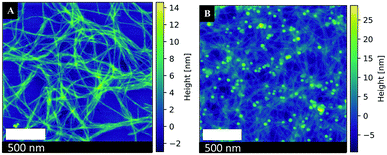 | ||
| Fig. 4 Atomic force microscopy images of (A) AFP fibrils (B) Immobilized Pt-NPs #5 on the surface of AFP fibrils. | ||
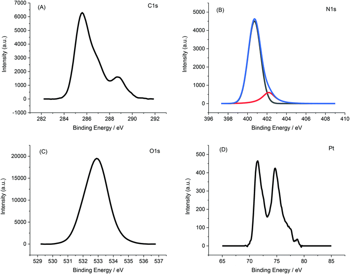
Fig. 5 displays a representative XPS spectrum of Pt-NPs-AFP fibrils composites. The C 1s peak in Fig. 5A can be resolved into two components, the peak at 284.8 eV revealing the hydrocarbon and the peak at 288.1 eV exhibiting a carboxyl and amine carbon peak. Deconvolution of the N 1s spectrum (Fig. 5B) gives two components that represent amino groups and amide groups in AFP fibrils, at 401.6 and 399.8 eV, respectively. The O 1s peak, corresponding to the carboxyl oxygen atoms in AFP fibrils, appears at 531.5 eV.
The Pt (4f7/2) and Pt (4f5/2) peaks materialize at 71 and 74.3 eV, respectively. All of these results confirm the deposition of Pt-NPs onto the surface of the AFP fibrils.
O2-plasma treatment of the nanoparticle-fibril-composites
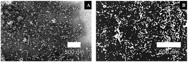
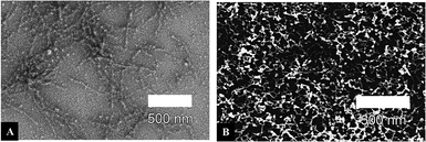
To prepare a network of connected Pt-NPs over a wide range on a surface, O2-plasma treatment was employed on the nanoparticles-fibrils-assemblies to eliminate the influence of the peptide fibrils, while at the same time maintain the optimal structure of crosslinked, evenly distributed Pt-NPs with a very large active surface area provided initially by immobilizing said nanoparticles on the fibrils' surface. The radiation of the O2-plasma cleaves the peptide bonds isotopically. Oxygen radicals immediately occupy the liberated bonds and prevent a recombination. Increasingly, short chain volatile substances are formed from the macromolecules and removed in the vacuum,47 leaving the nanoparticles in a network-like distribution and high metal loading – minus the influence of the peptide fibrils – to be used optimally for applications in catalysis, electronic materials and other corresponding fields. The SEM images in Fig. 6 show the effect of the O2-plasma cleaning procedure on the Pt-NPs-AFP fibrils-constructs with P = 300 W and 5 min treatment time. Fig. 6B confirms the elimination of the AFP fibrils after 5 min O2-plasma treatment. The image also shows the nanoparticles in an intermittent distribution with disconnected areas, indicating a high metal loading in areas the sample previously had high fibril densities, and lower metal loading in areas of the sample with lower fibril densities. Ultimately, a network of interconnected Pt-NPs has been arranged, which holds great potential for various applications.X-ray photoelectron spectroscopy (XPS) data were collected to further confirm the degradation of fibrils from the Pt-NPs-peptide fibril composites after O2-plasma treatment. As evident in (Table 3) and (Fig. 7), the peptide relevant elements, carbon and nitrogen, decline after the plasma procedure. The measured atomic percentage of elementary platinum amplifies comparatively by the elimination of the peptide fibrils to 1.43%.
| Sample | Surface atomic content (at%) | Atomic ratios | |||
|---|---|---|---|---|---|
| C 1s | N 1s | Pt 4f | Pt/C | Pt/N | |
| Pt-NPs-AFP fibril-assemblies before O2-plasma treatment | 32.33 | 5.15 | 0.12 | 0.004 | 0.023 |
| Pt-NPs-AFP fibril-assemblies after O2-plasma treatment | 18.52 | 1.69 | 1.43 | 0.077 | 0.846 |
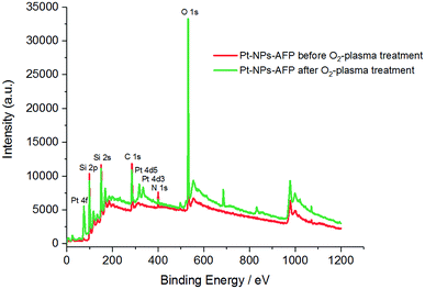 | ||
| Fig. 7 XPS spectra of the Pt-NPs-AFP fibrils assemblies before O2-plasma treatment (red), and the Pt-NPs-AFP fibrils composites after 5 min O2-plasma treatment at P = 300 W (green). | ||
Finally, the revelation of a larger amount of platinum, due to the degradation of the peptide fibrils, increases the Pt/C and Pt/N ratios after 5 min of 300 W O2-plasma radiation. Therefore, all of these results confirm the elimination of the AFP fibrils and the assembly of Pt-NPs as an interconnected network (see Scheme 1).
Synthesis of PVP-stabilized platinum nanoparticles
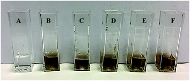
As demonstrated in (Table 1), Pt-NPs #1 (4 μl H2PtCl6/2600 μl solution) exhibited the highest agglomeration of nanoparticles due to possessing the highest concentration of H2PtCl6 precursor. As such, it was imperative to control the nanoparticle size of these Pt-NPs #1 and stabilize them against aggregation in order to make them better suited to be used in various applications. Herein, poly(vinyl pyrrolidone) (PVP) was used as the stabilizing agent, and the same novel method of VUV excimer lamp irradiation used above for the synthesis of Pt-NPs (see synthesis of platinum nanoparticles) was also used for the production of the PVP-stabilized Pt-NPs. The fabrication of the PVP-stabilized Pt-NPs was evidenced by a color change from colorless to black or dark brown (Fig. 8). The influence of polymer molecular weight (Mwt) on the platinum nanoparticle size was studied. The results are shown in Table 4.| Suspension name | H2PtCl6 [μl] | H2O [μl] | C3H8O [μl] | PVP [mg] | ∅ size [nm] | ||
|---|---|---|---|---|---|---|---|
| 5 min irradiation time | |||||||
| a Apparent size of particles indicates aggregates. | |||||||
| Pt-NPs #1 | 4 | 2400 | 200 | — | 249a (78%) | 1167a (21%) | 4333a (1%) |
| Pt-NPs #1 + PVP-10 kDa | 4 | 2400 | 200 | 11.5 | 3 (100%) | — | — |
| Pt-NPs #1 + PVP-40 kDa | 4 | 2400 | 200 | 11.5 | 5 (100%) | — | — |
| Pt-NPs #1 + PVP-58 kDa | 4 | 2400 | 200 | 11.5 | 6 (100%) | — | — |
| Pt-NPs #1 + PVP-360 kDa | 4 | 2400 | 200 | 11.5 | 9 (100%) | — | — |
| Pt-NPs #1 + PVP-1300 kDa | 4 | 2400 | 200 | 11.5 | 11 (75%) | 6 (25%) | — |
It is revealed that at a constant polymer concentration (Cp = 0.44%), the PVP polymer molecular weight remarkably influences the size of the Pt-NPs. Stabilization by PVP with Mwt = 10![[thin space (1/6-em)]](https://www.rsc.org/images/entities/char_2009.gif) 000 g mol−1 leads to the formation of very small particles (3 nm) of similar sizes. With increasing Mwt up to 40
000 g mol−1 leads to the formation of very small particles (3 nm) of similar sizes. With increasing Mwt up to 40![[thin space (1/6-em)]](https://www.rsc.org/images/entities/char_2009.gif) 000 g mol−1, the size of Pt-NPs increases to 5 nm. The augmentation of PVP Mwt results in an increase in nanoparticle size up to 6–11 nm, a part of which has a spherical or chain shape. The number of these nanoparticles also increases with increasing PVP Mwt. Under these conditions, nanoparticle agglomeration was not observed, as opposed to the non-stabilized Pt-NPs. This can also be seen in the AFM images in Fig. 9A and B.
000 g mol−1, the size of Pt-NPs increases to 5 nm. The augmentation of PVP Mwt results in an increase in nanoparticle size up to 6–11 nm, a part of which has a spherical or chain shape. The number of these nanoparticles also increases with increasing PVP Mwt. Under these conditions, nanoparticle agglomeration was not observed, as opposed to the non-stabilized Pt-NPs. This can also be seen in the AFM images in Fig. 9A and B.
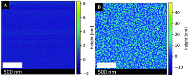 | ||
Fig. 9 Atomic force microscopy images of (A) a blank Si-wafer surface (B) the synthesized Pt-NPs #1 + PVP (10![[thin space (1/6-em)]](https://www.rsc.org/images/entities/char_2009.gif) 000 g mol−1, Cp = 0.44%). 000 g mol−1, Cp = 0.44%). | ||
Another direct influence on the nanoparticle size is the polymer concentration (Cp) (Table 5). In the presence of PVP with Mwt = 58![[thin space (1/6-em)]](https://www.rsc.org/images/entities/char_2009.gif) 000 g mol−1 and low PVP concentrations Cp = 0.30% and 0.44%, the sizes of the nanoparticles are, in both cases, ∼6 nm with no significant size differences apparent. However, for more concentrated PVP solutions, a slight size difference occurs. With PVP of Mwt = 10
000 g mol−1 and low PVP concentrations Cp = 0.30% and 0.44%, the sizes of the nanoparticles are, in both cases, ∼6 nm with no significant size differences apparent. However, for more concentrated PVP solutions, a slight size difference occurs. With PVP of Mwt = 10![[thin space (1/6-em)]](https://www.rsc.org/images/entities/char_2009.gif) 000 g mol−1 and concentrations Cp = 0.44% and 1.77%, there is a slight decrease of nanoparticle size from 3 nm to 2 nm for the higher concentrated PVP solution (Cp = 1.77%). Decreasing the PVP polymer concentration by a factor of 10 for the PVP with Mwt = 360
000 g mol−1 and concentrations Cp = 0.44% and 1.77%, there is a slight decrease of nanoparticle size from 3 nm to 2 nm for the higher concentrated PVP solution (Cp = 1.77%). Decreasing the PVP polymer concentration by a factor of 10 for the PVP with Mwt = 360![[thin space (1/6-em)]](https://www.rsc.org/images/entities/char_2009.gif) 000 g mol−1 displays a more significant increase in size. At Cp = 0.44%, the nanoparticle size is 9 nm; at Cp = 0.05%, most Pt-NPs have a size of 23 nm. Further decreasing PVP (Mwt = 1
000 g mol−1 displays a more significant increase in size. At Cp = 0.44%, the nanoparticle size is 9 nm; at Cp = 0.05%, most Pt-NPs have a size of 23 nm. Further decreasing PVP (Mwt = 1![[thin space (1/6-em)]](https://www.rsc.org/images/entities/char_2009.gif) 300
300![[thin space (1/6-em)]](https://www.rsc.org/images/entities/char_2009.gif) 000 g mol−1) concentration to Cp = 0.013%, demonstrates another similar increase of nanoparticle size.
000 g mol−1) concentration to Cp = 0.013%, demonstrates another similar increase of nanoparticle size.
| Suspension name | H2PtCl6 [μl] | H2O [μl] | C3H8O [μl] | PVP [mg] | ∅ size [nm] | ||
|---|---|---|---|---|---|---|---|
| 5 min irradiation time | |||||||
| a Apparent size of particles indicates aggregates. | |||||||
| Pt-NPs #1 | 4 | 2400 | 200 | — | 249a (78%) | 1167a (21%) | 4333a (1%) |
| Pt-NPs #1 + PVP-10 kDa, Cp = 0.44% | 4 | 2400 | 200 | 11.5 | 3 (100%) | — | — |
| Pt-NPs #1 + PVP-10 kDa, Cp = 1.77% | 4 | 2400 | 200 | 46 | 2 (100%) | — | — |
| Pt-NPs #1 + PVP-40 kDa, Cp = 0.44% | 4 | 2400 | 200 | 11.5 | 5 (100%) | — | — |
| Pt-NPs #1 + PVP-58 kDa, Cp = 0.44% | 4 | 2400 | 200 | 11.5 | 6 (100%) | — | — |
| Pt-NPs #1 + PVP-58 kDa, Cp = 0.30% | 4 | 2400 | 200 | 7.9 | 6 (100%) | — | — |
| Pt-NPs #1 + PVP-360 kDa, Cp = 0.44% | 4 | 2400 | 200 | 11.5 | 9 (100%) | — | — |
| Pt-NPs #1 + PVP-360 kDa, Cp = 0.05% | 4 | 2400 | 200 | 1.3 | 23 (71%) | 11 (29%) | — |
| Pt-NPs #1 + PVP-1300 kDa, Cp = 0.44% | 4 | 2400 | 200 | 11.5 | 11 (75%) | 6 (25%) | — |
| Pt-NPs #1 + PVP-1300 kDa, Cp = 0.013% | 4 | 2400 | 200 | 0.35 | 21 (100%) | — | — |
It is believed that the ζ-potential of the various PVP-stabilized platinum nanoparticle suspensions has been affected by the polymer presence, and thus does not show any significant differences with the variation of the nanoparticle sizes.
The average size of the PVP-stabilized Pt-NPs, listed in (Table 6), was slightly decreased from ∼11 to 5 nm when the VUV irradiation time was increased from 0.5 min to 5 min in this process. A more visible influence can be seen in the color intensity. With the increase of the VUV irradiation time, the intensity of the black color, which is characteristic of platinum nanoparticles, also increases. Zeta potential, however, does not exhibit any significant differences with the variation of the irradiation time due to PVP coating present.
| Irradiation time [min] | ∅ size [nm] | ||
|---|---|---|---|
| 0.5 | 13 (40%) | 8 (33%) | 4 (27%) |
| 1 | 11 (67%) | 6 (33%) | |
| 1.5 | 9 (60%) | 6 (40%) | — |
| 2 | 8 (100%) | — | — |
| 3 | 7 (66%) | 11 (34%) | — |
| 5 | 5 (100%) | — | — |
Immobilization of PVP-stabilized Pt-NPs on peptide fibrils
As established above (see synthesis of PVP-stabilized platinum nanoparticles), the PVP-stabilized Pt-NPs possess small sizes and no aggregates in their suspensions, hence making these stabilized nanoparticles better suited for the immobilization on peptide fibrils. Fig. 10 displays a SEM image of the immobilization of PVP-stabilized Pt-NPs on the surface of AFP fibrils via electrostatic attraction. It is necessary to note that at such polymer concentrations it is difficult to observe the nanoparticles or the fibrils due to the formation of very dense polymer films. The SEM image confirmed the attachment of copious amounts of Pt-NPs to the AFP fibrils' surfaces with a network-like morphology, where the Pt-NPs are lighting among a dark field of the PVP film.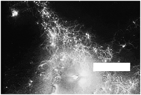 | ||
| Fig. 10 Scanning electron micrographs of immobilized PVP-40 kDa (Cp = 0.44%)-stabilized Pt-NPs on the surface of AFP fibrils (backscatter mode). | ||
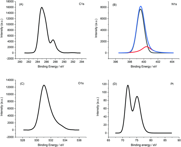
X-ray photoelectron spectroscopy (XPS) further confirmed the immobilization of PVP-Pt-NPs onto the AFP peptide fibrils. Fig. 11 presents the XPS spectrum of PVP-Pt-NPs-AFP fibrils nanocomposites.
O2-plasma treatment of the PVP-stabilized nanoparticle-fibril-composites
To construct a network of interconnected, smaller sized Pt-NPs stabilized by PVP, O2-plasma treatment was applied on PVP-stabilized nanoparticles-fibrils-composites to eradicate the influence of both the peptide fibrils and PVP film discussed above (see immobilization of PVP-stabilized Pt-NPs on peptide fibrils). This technique yields a crosslinked, connected assembly of stabilized, smaller sized Pt-NPs, which are better equipped with a large active surface area to be used ideally in catalysis, electronic materials and other fields, excluding any effects the PVP film or the peptide fibrils might have regarding the efficiency of operation.The SEM images in Fig. 12 illustrate the effect of the O2-plasma treatment on the PVP-stabilized Pt-NPs-AFP fibrils-assemblies with P = 300 W and 5 min treatment time. Fig. 12B confirms the removal of the AFP fibrils and PVP film after 5 min O2-plasma treatment. The images display the stabilized Pt-NPs in an interlocked arrangement, similar to nanowires, with the nanoparticles concentrated in areas of the sample that have previously had a high congregation of peptide fibrils.
XPS data also asserts the degradation of the peptide fibrils and the PVP film leading to the exposure of lager amounts of elementary platinum, as manifested in the increase of the Pt/C and Pt/N ratios after the application of O2-plasma for 5 min at 300 W. The data is presented in Table 7 and Fig. 13.
| Sample | Surface atomic content (at%) | Atomic ratio | |||
|---|---|---|---|---|---|
| C 1s | N 1s | Pt 4f | Pt/C | Pt/N | |
| PVP-stabilized Pt-NPs-AFP fibril-assemblies before O2-plasma treatment | 74.23 | 10.95 | 0.05 | 0.001 | 0.005 |
| PVP-stabilized Pt-NPs-AFP fibril-assemblies after O2-plasma treatment | 32.36 | 4.03 | 1.1 | 0.034 | 0.273 |
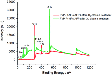 | ||
| Fig. 13 XPS spectra of the PVP-Pt-NPs-AFP fibrils assemblies before O2-plasma treatment (red), and the PVP-Pt-NPs-AFP fibrils composites after 5 min O2-plasma treatment at P = 300 W (green). | ||
Electrochemical behaviour of modified electrodes
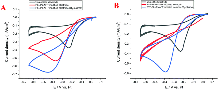
The Pt-NP and PVP-Pt-NP-AFP peptide fibril-composites and their O2-plasma treated assemblies possess interconnected, nanowire-resembling platinum structures. These network-like structures should provide an enhancement in the activity and catalytic performance. Cyclic voltammetry (CV) was used to investigate the electrocatalytic activity of the nanoparticle-fibril constructs for oxygen reduction. The obtained Pt-NPs-AFP fibrils and the PVP-Pt-NPs-AFP fibrils were supported on a platinum electrode, which is part of a three platinum-electrode system called ED-SE1-Pt (purchased from Micrux Technologies, Oviedo, Spain). Recent literature indicated that Pt can be used as a reference electrode under specific conditions in which traditional reference electrodes cannot be used.48 Fig. 14A displays CVs of the Pt-NPs-AFP fibrils-modified electrodes in O2-saturated 0.1 M H2SO4 solution. The O2-plasma treated Pt-NPs-AFP fibrils-modified electrode showed higher electrocatalytic activity compared to the non-O2-plasma treated modified electrode and the unmodified electrode, as judged from the increase in the current density, suggesting a pronounced electrocatalytic activity of the O2-plasma treated Pt-NPs-AFP fibrils toward oxygen reduction reaction (ORR). Fig. 14B displays CVs of the PVP-stabilized Pt-NPs-AFP fibrils-modified electrodes in saturated 0.1 M H2SO4 solution. The O2-plasma treated PVP-stabilized Pt-NPs-AFP fibrils-modified electrode also exhibited higher electrocatalytic activity compared to the unmodified electrode, manifesting as an increase in the current density. The non-O2-plasma treated PVP-stabilized Pt-NPs-AFP fibrils-modified electrode does not show a distinguished ORR peak. This is because the surface of the electrode is completely covered with the stabilizing agent PVP; it blocks the catalytic surface from the electrolyte and the faradic reactions will not take place, only the non-faradic double layer charging can be observed. The slight cathodic shifts (by ∼0.15–0.25 V) are consistent with this view. In other words, O2 reduction becomes more difficult at the covered electrode. O2-plasma treatment of the catalyst removes some amount of the PVP and fibrils from the surface of the electrode, exposing the Pt-NPs; this is evident from the CVs. A clear peak of ORR can be observed from the sample treated with O2-plasma and the overall voltammetric features suggest that it effectively removes both PVP and fibrils, indicating a noticeable electrocatalytic activity of the O2-plasma treated PVP-stabilized Pt-NPs-AFP fibrils toward ORR.Summary and conclusions
Herein, the viability of the immobilization of metal nanoparticles on peptide fibrils was demonstrated. The peptide AFP (aniline-GGAAKLVFF) was produced with a semi-automatic peptide synthesizer and analysed with MALDI-TOF. VUV irradiation was employed as a novel, simple, cost effective and environmentally friendly production process of both platinum nanoparticles (Pt-NPs) with different concentrations, and PVP-stabilized Pt-NPs with various polymer concentrations, molecular weights and irradiation times. A determination of the particle size of the PVP-stabilized Pt-NPs by dynamic light scattering (DLS) showed no agglomeration and smaller sized particles in comparison to the non-stabilized Pt-NPs. An analysis of the Pt-NPs by SEM exhibited a direct relationship between the platinum precursor concentration (H2PtCl6) and the aggregation of the particles. The examination of the PVP-stabilized Pt-NPs displayed a direct connection between the PVP polymer molecular weight (Mwt), its concentration (Cp) or the VUV irradiation time and the size of the synthesized particles.Immobilization of Pt-NPs onto the peptide fibrils via electrostatic interaction represents an appealing method for the formation of novel Pt-NPs-peptide fibril-composites, and is able to deposit nanoparticles on fibrils with different morphologies and high metal loading. To optimize the efficiency of this immobilization technique further, the peptide fibrils and the PVP film were both removed with O2-plasma treatment, leaving behind an interconnected network of Pt-NPs, resembling nanowires, exhibiting excellent electrocatalytic activities toward oxygen reduction, which is of special interest for polymer electrolyte fuel cells (PEFCS), batteries and many other miniature electrode applications. Further investigations are required to test the feasibility of this construct for PEFCS applications. Moreover, different amyloid fibrils could also be used as the support for the deposit of other metal nanoparticles (Au, Ag, Ni and others) via electrostatic association. Finally, the platinum loading on the peptide fibrils should be confirmed and the maximum load determined to make optimal use of the cost-intensive peptides.
Conflicts of interest
There are no conflicts to declare.References
- G. Schmid, V. Maihack, F. Lantermann and S. Peschel, J. Chem. Soc., Dalton Trans., 1996, 589–595, 10.1039/DT9960000589.
- M. Turner, V. B. Golovko, O. P. Vaughan, P. Abdulkin, A. Berenguer-Murcia, M. S. Tikhov, B. F. Johnson and R. M. Lambert, Nature, 2008, 454, 981–983 CrossRef CAS PubMed.
- G. Schmid and G. L. Hornyak, Curr. Opin. Solid State Mater. Sci., 1997, 2, 204–212 CrossRef CAS.
- A. W. Olsen and Z. H. Kafafi, J. Am. Chem. Soc., 1991, 113, 7758–7760 CrossRef CAS.
- D. de Caro, T. O. Ely, A. Mari, B. Chaudret, E. Snoeck, M. Respaud, J.-M. Broto and A. Fert, Chem. Mater., 1996, 8, 1987–1991 CrossRef CAS.
- L. M. Liz-Marzán, Mater. Today, 2004, 7, 26–31 CrossRef.
- H. Winnischofer, T. C. Rocha, W. C. Nunes, L. M. Socolovsky, M. Knobel and D. Zanchet, ACS Nano, 2008, 2, 1313–1319 CrossRef CAS PubMed.
- S. Gupta, Q. Zhang, T. Emrick, A. C. Balazs and T. P. Russell, Nat. Mater., 2006, 5, 229 CrossRef CAS.
- T. Yonezawa, S.-y. Onoue and N. Kimizuka, Langmuir, 2000, 16, 5218–5220 CrossRef CAS.
- B. D. Chithrani, A. A. Ghazani and W. C. Chan, Nano Lett., 2006, 6, 662–668 CrossRef CAS PubMed.
- P. K. Jain, K. S. Lee, I. H. El-Sayed and M. A. El-Sayed, J. Phys. Chem. B, 2006, 110, 7238–7248 CrossRef CAS PubMed.
- W. Shi, J. Wang, X. Fan and H. Gao, Phys. Rev. E: Stat., Nonlinear, Soft Matter Phys., 2008, 78, 061914 CrossRef PubMed.
- M. Sanles-Sobrido, M. A. Correa-Duarte, S. Carregal-Romero, B. Rodríguez-González, R. A. Álvarez-Puebla, P. Hervés and L. M. Liz-Marzán, Chem. Mater., 2009, 21, 1531–1535 CrossRef CAS.
- N. Tian, Z. Y. Zhou, S. G. Sun, Y. Ding and Z. L. Wang, Science, 2007, 316, 732–735 CrossRef CAS PubMed.
- N. Krasteva, I. Besnard, B. Guse, R. E. Bauer, K. Müllen, A. Yasuda and T. Vossmeyer, Nano Lett., 2002, 2, 551–555 CrossRef CAS.
- W. Tu, K. Takai, K.-i. Fukui, A. Miyazaki and T. Enoki, J. Phys. Chem. B, 2003, 107, 10134–10140 CrossRef CAS.
- R. F. Silva, D. R. Araújo, E. R. Silva, R. A. Ando and W. A. Alves, Langmuir, 2013, 29, 10205–10212 CrossRef CAS PubMed.
- F. He, D. Zhao, J. Liu and C. B. Roberts, Ind. Eng. Chem. Res., 2007, 46, 29–34 CrossRef CAS.
- N. Toshima and T. Yonezawa, New J. Chem., 1998, 22, 1179–1201 RSC.
- D. G. Duff, P. P. Edwards and B. F. G. Johnson, J. Phys. Chem., 1995, 99, 15934–15944 CrossRef CAS.
- H. Hirai, Y. Nakao and N. Toshima, J. Macromol. Sci., Part A: Pure Appl.Chem., 1979, 13, 727–750 CrossRef CAS.
- D. N. Furlong, A. Launikonis, W. H. F. Sasse and J. V. Sanders, J. Chem. Soc., Faraday Trans. 1, 1984, 80, 571–588 RSC.
- H. Bönnemann and G. A. Braun, Angew. Chem., Int. Ed. Engl., 1996, 35, 1992–1995 CrossRef.
- M. T. Reetz, W. Helbig, S. A. Quaiser, U. Stimming, N. Breuer and R. Vogel, Science, 1995, 267, 367–369 CrossRef CAS PubMed.
- S. K. Pilli, B. Viswanathan and T. Kanthadai Varadarajan, Synthesis and Characterization of Metal Nanoparticle Embedded Conducting Polymer–Polyoxometalate Composites, 2008 Search PubMed.
- A. Miyazaki, I. Balint and Y. Nakano, J. Nanopart. Res., 2003, 5, 69–80 CrossRef CAS.
- A. Salabat, G. Nabiyouni and M. R. Far, J. Exp. Nanosci., 2011, 6, 305–310 CrossRef CAS.
- J.-E. Park, M. Atobe and T. Fuchigami, Electrochim. Acta, 2005, 51, 849–854 CrossRef CAS.
- G. G. Couto, J. J. Klein, W. H. Schreiner, D. H. Mosca, A. J. de Oliveira and A. J. Zarbin, J. Colloid Interface Sci., 2007, 311, 461–468 CrossRef CAS PubMed.
- T. Teranishi, M. Hosoe, T. Tanaka and M. Miyake, J. Phys. Chem. B, 1999, 103, 3818–3827 CrossRef CAS.
- J. R. Croy, S. Mostafa, H. Heinrich and B. R. Cuenya, Catal. Lett., 2009, 131, 21–32 CrossRef CAS.
- K.-S. Kim, D. Demberelnyamba and H. Lee, Langmuir, 2004, 20, 556–560 CrossRef CAS PubMed.
- K. Kurihara, J. Kizling, P. Stenius and J. H. Fendler, J. Am. Chem. Soc., 1983, 105, 2574–2579 CrossRef CAS.
- B. Zhou, Z. Sun, D. Li, T. Zhang, L. Deng and Y.-N. Liu, Nanoscale, 2013, 5, 2669–2673 RSC.
- J. Lee, G. Du Plessis, D. W. M. Arrigan and D. S. Silvester, Anal. Methods, 2015, 7, 7327–7335 RSC.
- C. Elsner, A. Prager, U. Decker, S. Naumov and B. Abel, Am. J. Nano Res. Appl., 2014, 2, 1–8 Search PubMed.
- M. Y. Lin, H. M. Lindsay, D. A. Weitz, R. Klein, R. C. Ball and P. Meakin, J. Phys.: Condens. Matter, 1990, 2, 3093 CrossRef.
- J. S. Smith, D. Bedrov and G. D. Smith, Compos. Sci. Technol., 2003, 63, 1599–1605 CrossRef CAS.
- Y. Q. Li, N. J. Tao, J. Pan, A. A. Garcia and S. M. Lindsay, Langmuir, 1993, 9, 637–641 CrossRef CAS.
- H.-J. Butt, Biophys. J., 1991, 60, 1438–1444 CrossRef CAS PubMed.
- C. S. Hodges, J. A. S. Cleaver, M. Ghadiri, R. Jones and H. M. Pollock, Langmuir, 2002, 18, 5741–5748 CrossRef CAS.
- E. R. Chan, L. C. Ho and S. C. Glotzer, J. Chem. Phys., 2006, 125, 064905 CrossRef PubMed.
- O. S. Makin and L. C. Serpell, FEBS J., 2005, 272, 5950–5961 CrossRef CAS PubMed.
- M. R. Sawaya, S. Sambashivan, R. Nelson, M. I. Ivanova, S. A. Sievers, M. I. Apostol, M. J. Thompson, M. Balbirnie, J. J. Wiltzius, H. T. McFarlane, A. O. Madsen, C. Riekel and D. Eisenberg, Nature, 2007, 447, 453–457 CrossRef CAS PubMed.
- M. A. Correa-Duarte, N. Sobal, L. M. Liz-Marzán and M. Giersig, Adv. Mater., 2004, 16, 2179–2184 CrossRef CAS.
- M. A. Correa-Duarte and L. M. Liz-Marzan, J. Mater. Chem., 2006, 16, 22–25 RSC.
- F. D. Egitto, Pure Appl. Chem., 1990, 62, 1699 CAS.
- K. Kasem and S. Jones, Platinum as a Reference Electrode in Electrochemical Measurements, 2008 Search PubMed.
| This journal is © The Royal Society of Chemistry 2019 |

