DOI:
10.1039/C8RA07887D
(Paper)
RSC Adv., 2019,
9, 3918-3926
Vibration induced refrigeration and energy harvesting using piezoelectric materials: a finite element study
Received
22nd September 2018
, Accepted 3rd January 2019
First published on 29th January 2019
Abstract
In this study, the bi-functional performance of a small-scale piezoelectric cantilever, which coupled piezoelectric and elastocaloric phenomena in a single device to produce energy harvesting as well as refrigeration effects due to vibration, has been investigated. Finite element modeling has been used to examine the performance of the device. The basic structure of the device is a cantilever that vibrates between two thermal bodies (hot and cold). The properties of BaTiO3 (single crystal) were used to examine the bi-functional performance of piezoelectric cantilevers. In this study, different cases have been investigated, which are based on a number of cantilevers between hot and cold thermal bodies. When the number of cantilevers is one, the net cooling is 0.3 K and the power is 0.03 μW, while for four cantilevers, the net cooling is 1.2 K and 0.13 μW of power is produced. The results show that as we increase the number of cantilevers, a greater refrigeration effect is produced and higher power across the electrical load is achieved.
Introduction
Piezoelectric materials are known for their sensing and actuation applications. These materials have also shown promising results in other emerging fields, such as photovoltaics and photocatalysis.1–4 In the last decade, the piezoelectric effect has also been well explored for energy harvesting applications.5–10 Large numbers of devices have been proposed theoretically and a few prototypes have also been fabricated on the laboratory scale.11–14 These devices have shown interesting performance properties from the microscale to the macroscale. Among those reported in the literature, the simplest design that has been widely studied is cantilever-based energy harvesting. Another emerging area is solid state refrigeration, where the electrocaloric effect associated with ferroelectric materials has been extensively investigated in the last couple of years.15–17 Almost the whole family of ferroelectric materials has been investigated from an electrocaloric viewpoint. Some devices have been proposed from regenerator and refrigeration application viewpoints.17,18 Recently, another caloric effect based on mechanical force input, known as the mechanocaloric effect, has been demonstrated in this class of materials.15,19,20 The elastocaloric effect has been widely reported in shape memory alloys and a few polymers where the cooling magnitude and coefficient of performance were found to be superior to the electrocaloric effect in ferroelectric materials.21,22 Interestingly, the elastocaloric effect has also been observed in ferroelectric materials.23 In this context, devices based on the elastocaloric effect associated with ferroelectricity have not proposed so far. In this article, we have attempted a finite element-based theoretical study on a cantilever type refrigeration system where the input mechanical vibrations are able to vibrate a cantilever and stresses generated in the cantilever are able to induce a cooling effect. Continuous vibrations are also able to act as a thermal switch for heat transfer from a lower temperature body to a sink. Interestingly, this cantilever is also able to produce electricity due to the piezoelectric effect. Hence, we compiled results regarding the bifunctional performance of piezo-cantilevers in view of vibrational energy harvesting as well as refrigeration effects for small scale devices. To the best of our knowledge, no such study has been proposed so far.
Materials and methods
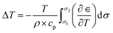
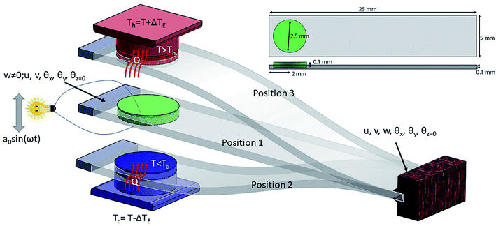
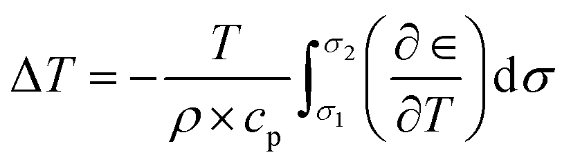
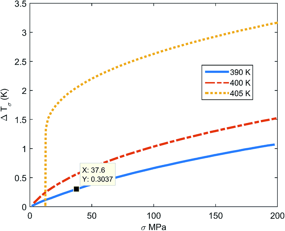
Ferroelectrics are promising materials for solid-sate cooling refrigeration technology. These materials show significantly entropy change when an external field (stress, pressure or electrical) is applied, due to changes in polarization. Yang Liu et al.24 have shown that BaTiO3 has huge elastocaloric strength (|ΔT|/Δσ), as this material shows a sharp first-order phase transition. Fig. 1 shows the elastocaloric behavior of BaTiO3, demonstrating the change in temperature upon applying stress at ambient temperatures from 390–405 K. These results are adopted from the literature.24 It is key to note that the elastocaloric effect may be poling/load direction dependent, which has not been explored by any researchers so far. Hence, we have ignored this dependency with regards to the performance of the proposed devices. The objective of the present work is to demonstrate the feasibility of vibration induced refrigeration and energy harvesting, which has not been reported so far. As the stress increases, the change in temperature (ΔT) increases. However, there is limit to the applied stress, which depends on the application. The same material, BaTiO3, also shows piezoelectric behavior, which has been reported by several research groups.25–28 The material properties of single crystal BaTiO3 have been collected from the literature.25 BaTiO3 can be a promising ferroelectric for harvesting energy along with demonstrating refrigeration effects. However, it is not straightforward to obtain both elastocaloric and piezoelectric effects simultaneously in device form. This requires proper design through considering the geometrical parameters. Fig. 2 shows a schematic diagram of the working principle of the device. For this study, a cantilever structure has been chosen as this has a greater advantage if the input energy is vibrational with a smaller amplitude.29 This cantilever is made of platinum with a BaTiO3. Platinum has been considered as a material due to its superior mechanical properties, which help to induce larger stress at a low amplitude of vibration. The purpose of the host structure is to shift the natural axis of the patch so that there is either tensile stress or compression stress in the patch at any time. The dimensions of the cantilever and the BaTiO3 patch are shown in the inset of Fig. 2. The patch is connected to the electrical load with the help of electrodes so that it can extract the electrical energy that arises due the piezoelectric effect. The thicknesses of the electrodes are taken as negligible, as these electrodes do not affect the stiffness of the structure. To generate a certain level of stress, the boundary conditions play a crucial role for the cantilever. For this, one end of the cantilever is fully clamped while the other end is partially clamped so that this end can vibrate in a transverse direction. Two thermal bodies (copper) have been placed on the upper and lower sides of the cantilever in a perpendicular line with the patch, and the distance between these two bodies decides the vibration amplitude of the cantilever. When the cantilever moves to either extreme side, the cantilever makes contact with one of these thermal bodies. In Fig. 2, three positions of the cantilever are shown. In the first position, the patch is in a zero-stress state, as the transverse deflection is zero. In the second position, the patch is in a compression stress state, as the transverse deflection is minimum. To change the state from the first to the second, the patch starts to release heat due to the elastocaloric effect, which decreases the temperature of the patch at the end of this cycle. The elastocaloric ΔT value for any material can be determined using the following expression:30| |
 | (1) |
 |
| | Fig. 1 The temperature change (ΔT) under various stress values for BaTiO3 at 390–405 K.24 | |
 |
| | Fig. 2 A schematic diagram of the piezoelectric and elastocaloric effects in a cantilever. | |
Here the symbols represent their usual quantities: density (ρ); specific heat capacity (cp); strain (∈); stress (σ); and temperature (T). Eqn (1) represents a modified form of the classical Maxwell's relation for calculating entropy change within a ferroic material.
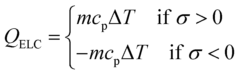
At the time of contact with the lower thermal body, there is temperature difference between the thermal body and the patch, due to which heat transfers from the thermal body to the patch. Equal temperature is achieved due to this heat transfer. This decreases the overall temperature of the thermal body and makes it cold. Similarly, when the cantilever moves from the second to the third position, the temperature of the patch increases due to the entropy change and it has a higher temperature than the thermal body. As there is a temperature difference between the two bodies at the time of contact, heat transfer occurs between the patch and the thermal body. Hence, by repeating the vibration cycle, the patch extracts heat from the lower thermal body and transfer it to the upper thermal body. The heat generation behavior shown by the cantilever can be written as:
| |
 | (2) |
where
m is the mass of the cantilever,
cp is the specific heat capacity (BaTiO
3: 434 J kg
−1 K
−1; copper: 385 J kg
−1 K
−1), and Δ
T is the temperature change during vibration. During subsequent vibration cycles, heat moves from the lower thermal body to the upper body, which decreases the temperature of the lower thermal body (cold side) and increases the temperature of the upper thermal body (hot side).
During the vibrations, as the patch goes through a cycle of stresses (tensile and compression), it generates electrical charge at the surface of the patch due to the piezoelectric effect.
For a piezoelectric material, the constrictive equations can be represented as31
where
cE is the fourth-order elastic tensor and
E is electrical field. The term
εS is the second-order dielectric constant tensor and
S represents strain. The third-order tensor of the piezoelectric coefficient is expressed by the term
e. The term
T represents the second-order stress tensor, whereas
D represents the electric displacement vector.
Eqn (3) indicates the stress generation in a piezoelectric material upon applying an electrical field, even if the mechanical load is zero, which is called a reverse piezoelectric effect.
Eqn (4) indicates the charge generation due to a mechanical load in the absence of an electric field due to the piezoelectric effect.
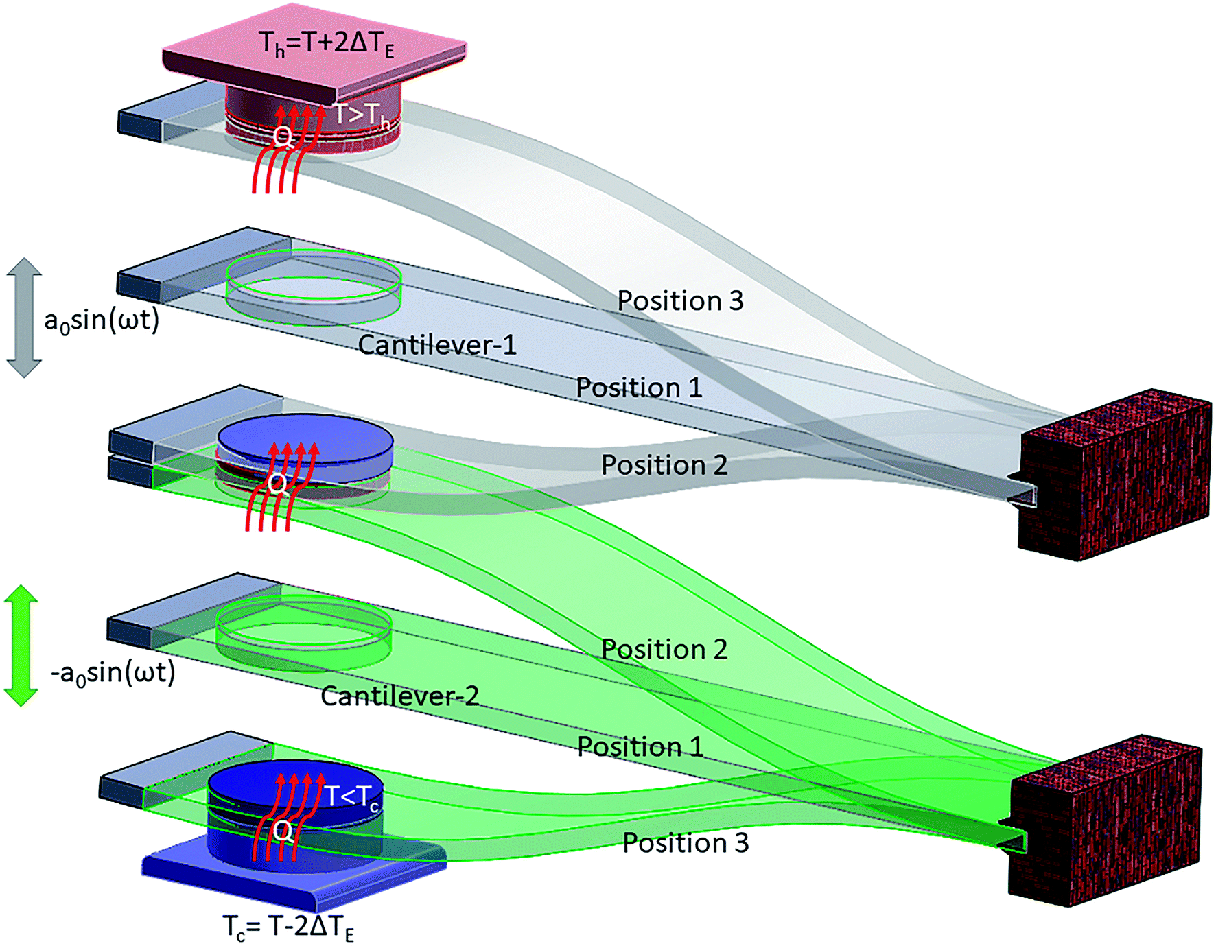
In the presented mechanism, two phenomena, elastocaloric and piezoelectric effects, are involved. To simulate these effects, the finite element method is a promising numerical technique, as this method has wide acceptance in the fields of heat transfer and energy harvesting applications. To obtain the values of the stresses in the patch due to vibration, the structure has been discretized into a large number of elements. Here, shell elements have been used to discretize the structure as a thin cantilever. This element has six mechanical degrees of freedom (u, v, w, θx, θy, θz) per node and one electrical degree of freedom (ϕ) per element. As this formulation is widely reported in the literature, details of the finite element formulation are mentioned in Appendix A. By using this formulation, stress values can be easily obtained at any point within the structure during the vibration cycle. In this work, we used average stress values for the patch to obtain the temperature difference (ΔT) due to the elastocaloric effect. By using eqn (2), we calculate the net heat generation in the patch at the time of contact with either thermal body (upper or lower). As the system has a lower vibrational frequency, it can be assumed that there is no additional heat generation due to impact. However, there is a limit to the heat transfer between the two thermal bodies when using a single cantilever. A single cantilever cannot transfer heat beyond a certain limit, as it becomes saturated once the temperature difference between the two thermal bodies is 2ΔT. To go beyond this limit, the cascading of cantilevers is a promising solution, as cascading is a widely popular mechanism to increase heat transfer between two thermal bodies. Fig. 3 shows a schematic diagram of the cascading of cantilevers between two thermal bodies. Here, two cantilevers are used to transfer heat from the lower thermal body to the high temperature body. Both cantilevers are vibrated in an antiphase fashion so that during the contact of the attached patches they have a maximum difference between their temperatures and, subsequently, heat transfer can take place. By using this cascading setup, the net temperature difference between the two thermal bodies will be 4ΔT. The working mechanism is shown in Fig. 4, from step I to step VI. Initially, all bodies have equal temperature, as shown in step I. In step II, both the cantilevers (C1 and C2) vibrate in opposite directions so that one patch (attached to C2) increases its temperature and the other patch (attached to C1) decreases its temperature. In step III, both patches come into contact with a thermal body: the upper cantilever (C2) contacts the upper thermal body (sink) and transfers heat to it so that the temperature of the thermal body rises. The lower cantilever (C1) comes into contact with the lower thermal body and transfers heat from it so that the temperature of the thermal body decreases. In step IV, both the cantilevers move toward each other and during this cycle the values of the temperatures of the attached patches are opposite to those in step II. In step V, the patches make contact and heat transfer takes place from C1 to C2; the cycle is repeated with different initial temperatures in step VI.
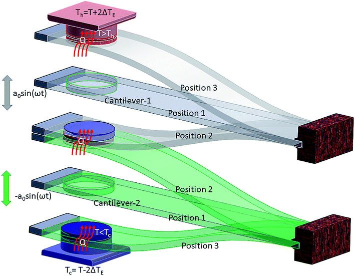 |
| | Fig. 3 The working mechanism of refrigeration due to the elastocaloric effect. | |
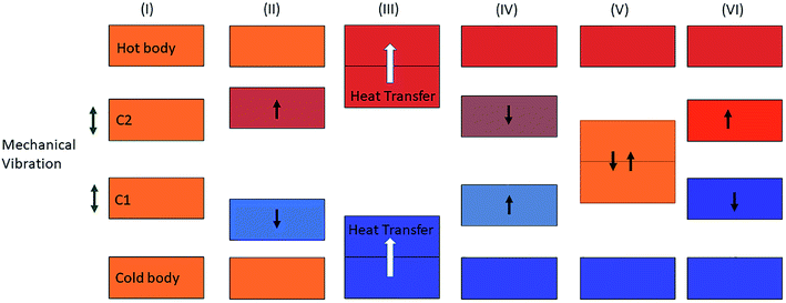 |
| | Fig. 4 The block diagram mechanism for the refrigeration effect between the cold and hot bodies. | |
Results and discussion
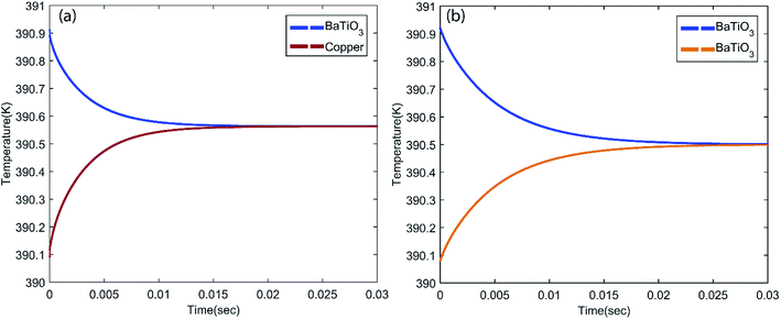
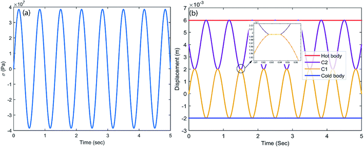
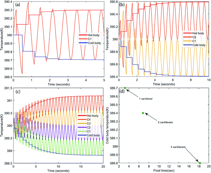
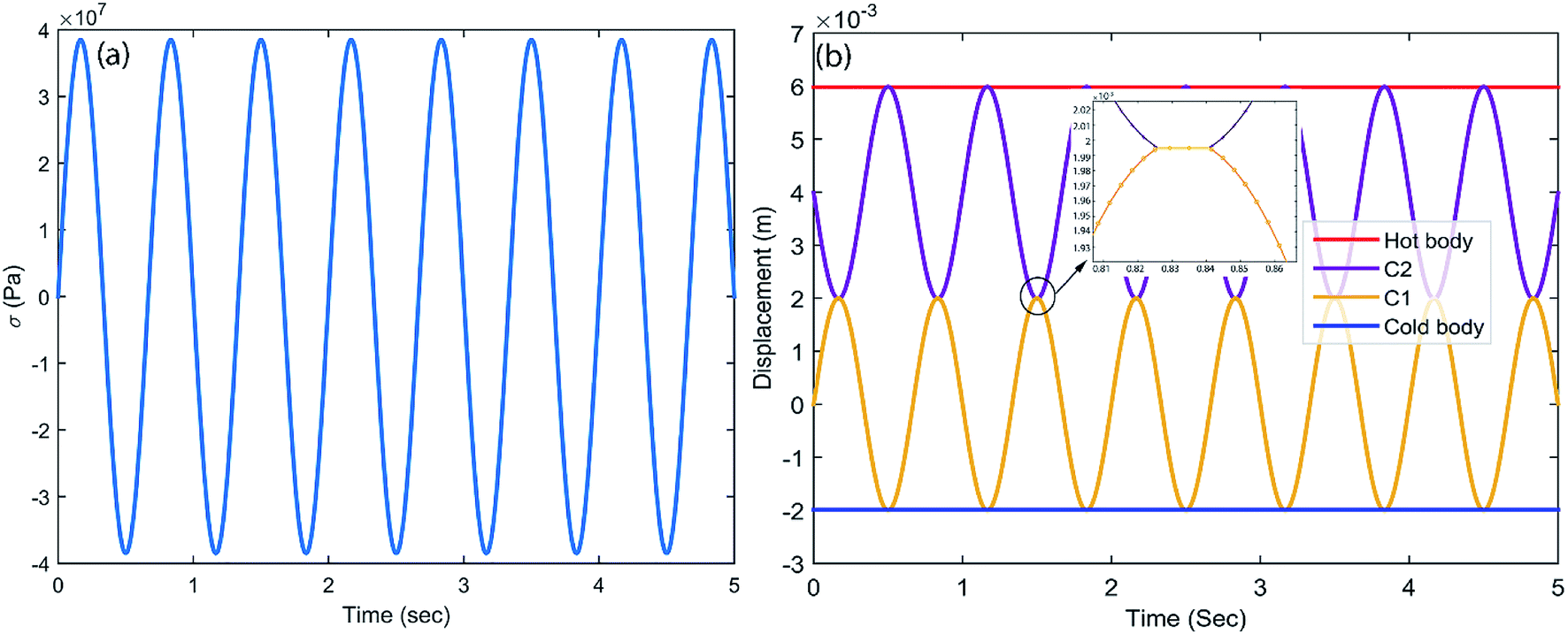
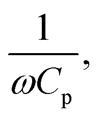
In this study, the piezoelectric and elastocaloric effects of a ferroelectric material have been coupled. The working principles of these phenomena are different; however, both can be driven with the same input vibrational energy. This aspect can be used to make a bi-functional hybrid device. However, this requires optimization so that both phenomena can work in the device without suppressing each other. After selection of the material, the geometrical parameters of the device must be optimized. The generated stresses and the heat transfer time between the cantilevers are major constraints during the geometrical parameter optimization. As shown in Fig. 1, the temperature difference (ΔT) is 0.303 K at a stress level of 37 MPa. It is a major constraint to develop sufficient stress (37 MPa) in the cantilever. By using genetic algorithm (GA) optimization,32 we obtained the geometrical parameters for the cantilever, which are shown in the inset of Fig. 2. The cantilever made of platinum includes a circular BaTiO3 patch (diameter = 2.5 mm; thickness = 0.1 mm). The thickness of the host layer without the patch is 0.1 mm, while the thickness of the host layer at the patch is 0.05 mm. The material properties are given in Table 1. The selection of the vibration amplitude and frequency depends on the desired stress level and heat transfer time between the two cantilevers. Here, the heat transfer time between the two different bodies is calculated with the help of finite element analysis. For this purpose, a heat transfer study using finite element analysis has been done for two different cases (first, heat transfer between BaTiO3 and a sink or source body that is made of copper, and second, heat transfer between BaTiO3 and a BaTiO3 patch), as shown in Fig. 5. From the figure, it can be concluded that the thermal equilibrium time for BaTiO3 and copper is ∼0.018 s, while the thermal equilibrium time for BaTiO3 and BaTiO3 is ∼0.03 s, as shown in Fig. 5a and b, respectively. In the latter case, the thermal equilibrium time is higher due to the small value of the thermal conductivity of BaTiO3. As the cantilevers are in a continuous vibration mode, it is difficult to hold the cantilevers in contact for a longer time to allow thermal equilibrium. However, this can be achieved through transferring the heat in subsequent cycles continuously. The contact time between the two bodies depends on the vibration frequency, however a higher frequency can also cause excessive impact force and noise during contact. In this study, the vibration amplitude of cantilever excitation is 2 mm with a frequency of 1.5 Hz selected because at this frequency the time for heat transfer between the two thermal bodies is ∼0.015 s. Based on the geometrical parameters of the cantilever, the stress in the patch is calculated, which is shown in Fig. 6a. In this figure, the maximum stress is 37 MPa, which is desired to get a 0.303 K temperature difference due to the elastocaloric effect. Fig. 6b shows the positions of each cantilever during the vibration along with the hot body and cold body. Each cantilever vibrates between the hot and cold bodies, which facilitates the transfer of heat from the cold to the hot body. In the inset of Fig. 6b, the heat transfer time is shown between two cantilevers, which is ∼0.015 s. After obtaining the desired stress level and heat transfer time, we studied the performance of the device with regards to both piezoelectric and elastocaloric effects.
Table 1 Material properties at room temperature
| Material property |
BaTiO3 (ref. 25 and 33) |
Copper |
Platinum |
| Elastic compliance (×10−12 m2 N−1) |
|
|
|
| S11E |
8.05 |
— |
— |
| S33E |
15.7 |
— |
— |
| S12E |
−2.35 |
— |
— |
| S13E |
−5.24 |
— |
— |
| S44E |
18.4 |
— |
— |
| S66E |
8.84 |
— |
— |
| Young's modulus (GPa) |
— |
120 |
168 |
| Density (Kg m−3) |
5840 |
8960 |
21![[thin space (1/6-em)]](https://www.rsc.org/images/entities/char_2009.gif) 450 450 |
| Piezoelectric constant (pC/N) |
−34.5 |
— |
— |
| Dielectric constant |
168 |
— |
— |
| Thermal conductivity (W mK−1) |
2.61 |
400 |
71.6 |
| Specific heat (J kg−1 m−1) |
434 |
385.6 |
130 |
 |
| | Fig. 5 The heat transfer time between (a) BaTiO3 and copper and (b) BaTiO3 and BaTiO3. | |
 |
| | Fig. 6 (a) The generated stresses in a cantilever during vibration, and (b) cantilever movement during vibration between hot and cold bodies. | |
The present study was performed with both a single cantilever and arrays of cantilevers (2 and 4). For energy harvesting, optimized resistance across the piezoelectric patch is used as the electrical load. The value of optimized resistance is equal to  where ω is the vibrational angular frequency and Cp is the capacitance of the piezoelectric patch. During vibration, tensile and compression stresses are generated in the piezoelectric patch, due to which a voltage is generated across the load. Fig. 7a shows the voltage across the load for different cases. When the number of cantilevers is one then the value of voltage across the load is 0.8 V, which increases linearly upon increasing the number of cantilevers. The voltage across the load is 3.2 V if the number of cantilevers is four. In the inset, the typical voltage across the load with time is plotted, which varies according to the stresses in the piezoelectric patch. From Fig. 7a, it can be concluded that the voltage increases if the number of cantilevers increases.
 |
| | Fig. 7 The piezoelectric energy harvesting output for different numbers of cantilevers: (a) the voltage output; and (b) the power output. | |
The power across the load is also another important parameter for an energy harvester. Here, power across the load can be defined as  where V is the voltage across a resistance R. Fig. 7b shows the power across the load for different numbers of cantilevers. The power is 0.03 μW for a single cantilever device; this increases to 0.13 μW if four cantilevers are installed. The variation of the power with respect to time is shown in the inset of Fig. 7b.
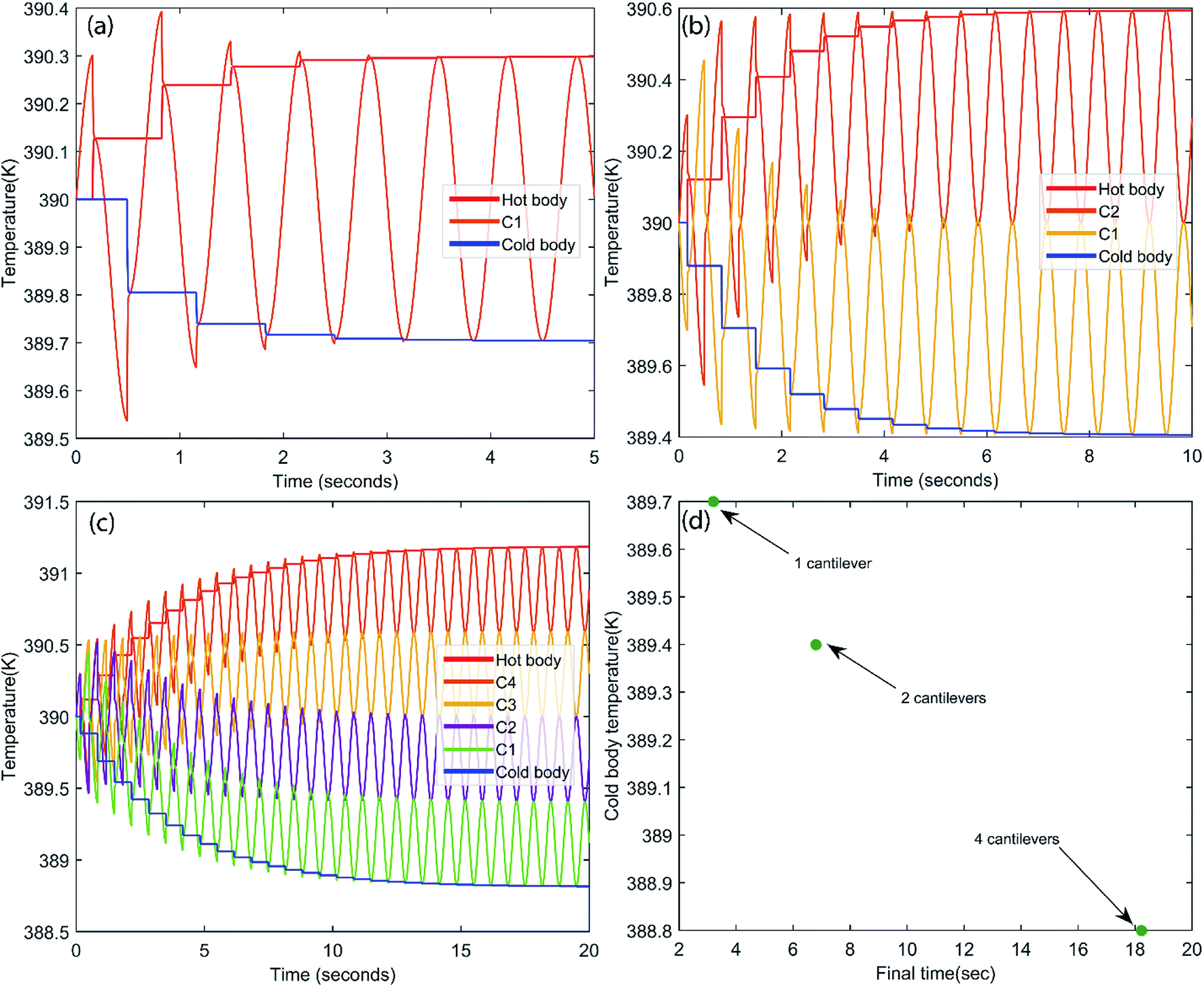
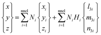
Further, we studied the cooling performance of the devices through the elastocaloric effect. The operating initial temperature is assumed to be 390 K. During vibration, due to the elastocaloric effect, the patch generates and absorbs the heat that has been transferred from the cold body to the hot body. Fig. 8a shows the heat transfer from the cold to the hot body as a function of time if one cantilever is operated between these two thermal bodies. At the end of the first cycle, net cooling of ∼0.2 K is generated at the cold body, which is marginally increased in subsequent cycles. After three cycles, thermal equilibrium is achieved, and no further cooling is produced. Fig. 8b shows the heat transfer using two cantilevers. This time, the net cooling increases two-fold, i.e., it is ∼0.6 K for the cold body. Here we increase the number of cantilevers, taking more cycles to achieve thermal equilibrium and providing more cooling compared to the previous case. This system was saturated after 7.2 s, when the hot body temperature rose to 390.6 K and the cold body temperature dropped to 389.4 K. In the next example, we further increased the number of cantilevers (four) between the hot and cold bodies. The outcome of this configuration is plotted in Fig. 8c. It takes more cycles to reach saturation, when no further cooling is produced. After 18 s, this configuration achieved thermal equilibrium, however it produces a greater cooling effect than both previous cases. The net temperature difference between the hot body and cold body is ∼2.4 K and the cold body temperature drops to 388.88 K from an initial temperature of 390 K. We observe that the net cooling effect increases if the number of cantilevers increases. It is assumed that distance between the hot and cold bodies varies for different numbers of cantilevers so that each cantilever can vibrate with a desired selected amplitude. If the distance between the hot and cold bodies is constant, an increase in the number of cantilevers can reduce the vibration amplitude, which will ultimately reduce the cooling effect per cantilever. To get a better cooling effect, we have to use a higher number of cantilevers between the hot and cold bodies, but this also increases the thermal equilibrium time, as shown in Fig. 8d. Fig. 8d shows the maximum achieved cooling temperature of the cold thermal body for different numbers of cantilevers with respect to time. It can be concluded that a better cooling temperature can be achieved by increasing the number of cantilevers, but this also increases the equilibrium time. A higher number of cantilevers takes a longer time to reach thermal equilibrium and subsequently decrease the cold body temperature more. These results show the promising concept of simultaneous energy harvesting and refrigeration using a piezoelectric embedded cantilever. However, it is desirable to prove this concept experimentally in the near future.
 |
| | Fig. 8 Refrigeration effects due to the elastocaloric effect for different numbers of cantilevers: (a) n = 1; (b) n = 2; and (c) n = 4. (d) The final time (to achieve maximum cooling) vs. the achieved cooling temperature for different numbers of cantilevers. | |
Conclusions
The bi-functional performance of a small-scale piezoelectric device has been investigated. The purpose of this study was to couple piezoelectric and elastocaloric phenomena into a single device, producing energy harvesting as well as refrigeration effects due to vibrations. For this purpose, a single crystal BaTiO3 patch was attached to the platinum cantilever, as this has good elastocaloric and piezoelectric properties. This cantilever vibrates between two thermal bodies (hot and cold bodies). Vibrations generate alternate stress cycles (tension and compression) in the patch, generating charges at the electrodes and a temperature difference. As the cantilever contacts the hot and cold bodies in the vibration cycle, it transfers heat from the cold body to the hot body. In this study, three different cases have been investigated, which are based on a number of cantilevers existing between the hot and cold thermal bodies. When the number of cantilevers is one, the net cooling is 0.3 K and the power is 0.03 μW, while for four cantilevers, the net cooling is 1.2 K and 0.13 μW of power is produced.
Appendix A
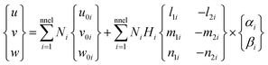
Using shape functions, the coordinate of any point P inside the kth layer within the element can be written as| |
 | (A.1) |
where,
and t0k,i is the mid-plane distance of the kth layer from the neutral plane at node i and tki is the thickness of the kth layer at the node. l3i, m3i and n3i are the directional cosines of the normal unit vector V3i at node i. If the thickness is uniform at each node, then Hi = H. Using shape functions, one obtains the displacement of any point P inside the kth layer within the element as| |
 | (A.2) |
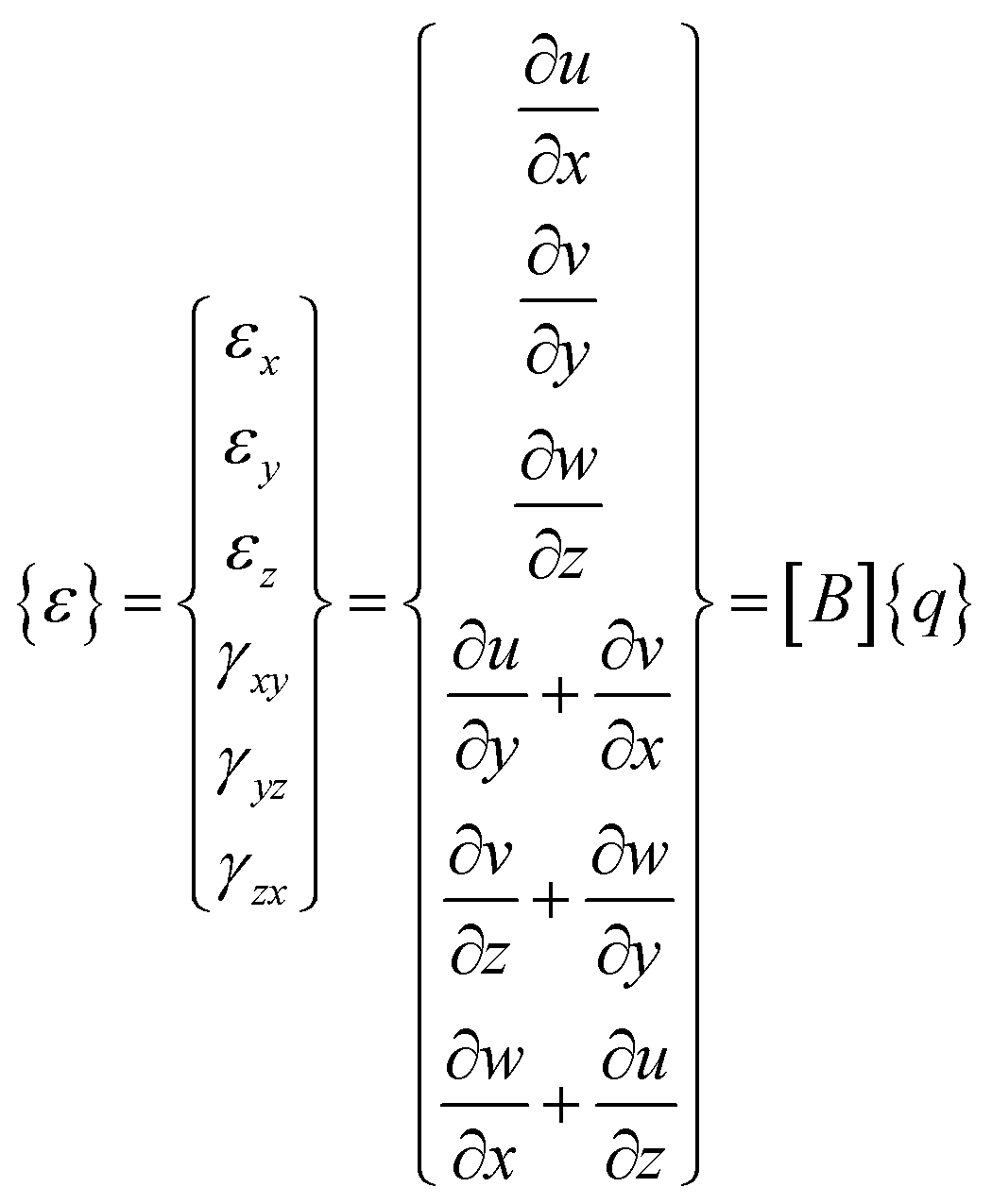
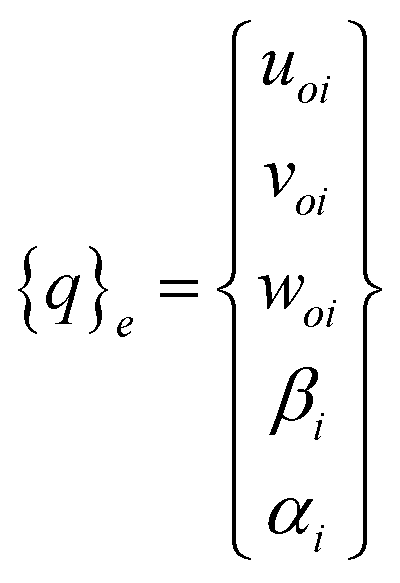
where l1i, m1i and n1i are the directional cosines of the tangent unit vector V1i and l2i, m2i and n2i are the directional cosines of the tangent unit vector V2i at node i. Therefore, each node has 3 translation degrees of freedom (u0i, v0i, w0i) in terms of global coordinates and two rotational degrees of freedom (αi and βi) about the local coordinates. The strain vector ε is defined by the first partial derivative of the displacement vector [u, v, w, α, β]T using a differential operator matrix as follows:| |
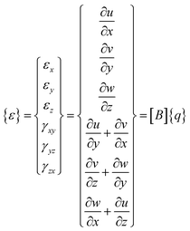 | (A.3) |
where,
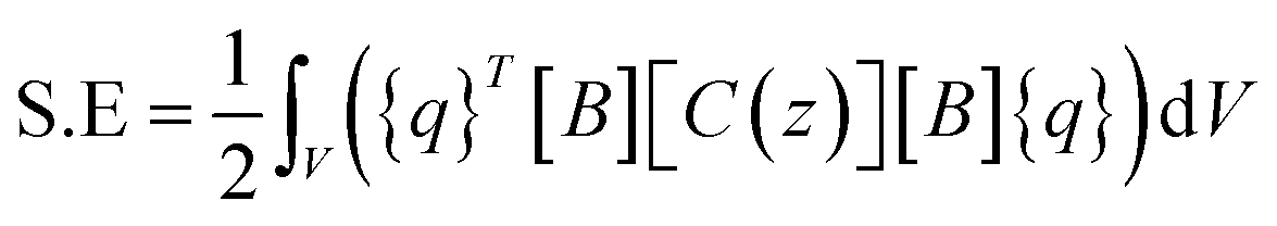
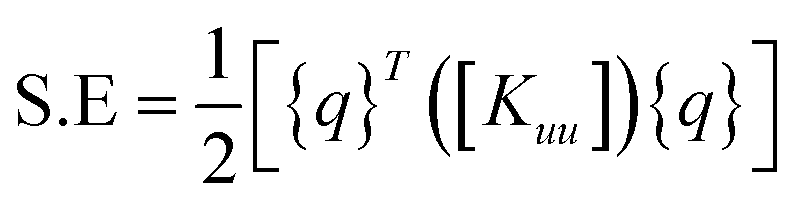
and [B] is the strain displacement matrix. The strain energy in an element is given by:
| |
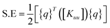 | (A.4) |
where
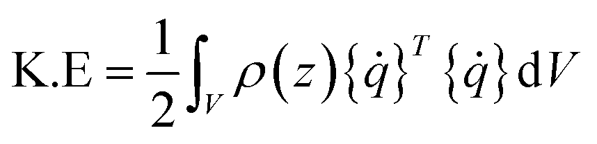
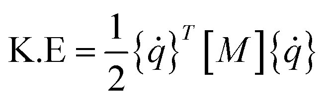
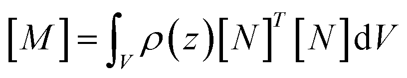
The kinetic energy in an element is given by:
| |
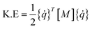 | (A.5) |
where
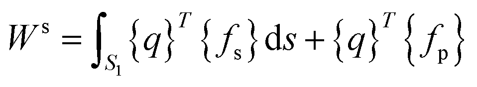
N are the shape functions. The total external work done on the element is given by:
| |
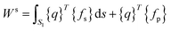 | (A.6) |
where
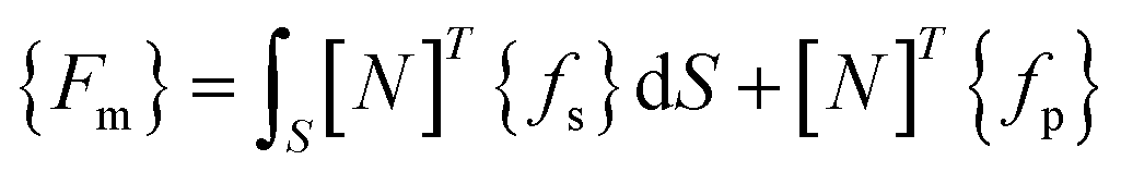
S1 is the surface area on which the external force is acting, {
fs} is the surface force intensity and {
fp} is the point load.
By using Hamilton's principle, the final equations can be written as:
Using eqn (A.4–A.7) we get:
| |
[M]{![[q with combining umlaut]](https://www.rsc.org/images/entities/i_char_0071_0308.gif) } + [C]{ } + [C]{![[q with combining dot above]](https://www.rsc.org/images/entities/i_char_0071_0307.gif) } + [K]{q} = {F} } + [K]{q} = {F}
| (A.7) |
Conflicts of interest
There are no conflicts to declare.
References
- J. M. Wu, W. E. Chang, Y. T. Chang and C. K. Chang, Adv. Mater., 2016, 28, 3718–3725 CrossRef CAS PubMed.
- H. Huang, S. Tu, C. Zeng, T. Zhang, A. H. Reshak and Y. Zhang, Angew. Chem., Int. Ed., 2017, 56, 11860–11864 CrossRef CAS PubMed.
- C. F. Tan, W. L. Ong and G. W. Ho, ACS Nano, 2015, 9, 7661–7670 CrossRef CAS PubMed.
- X. Xue, W. Zang, P. Deng, Q. Wang, L. Xing, Y. Zhang and Z. L. Wang, Nano Energy, 2015, 13, 414–422 CrossRef CAS.
- J. Y. Park, Piezoelectric MEMS Energy Harvesters, 2015 Search PubMed.
- Y. Leprince-Wang, Piezoelectric ZnO nanostructure for energy harvesting, 2015, vol. 1 Search PubMed.
- M. A. Karami and D. J. Inman, in Micro Energy Harvesting, 2015, pp. 435–458 Search PubMed.
- S. P. Beeby, M. J. Tudor and N. M. White, Meas. Sci. Technol., 2006, 17(12), R175 CrossRef CAS.
- A. Khan, Z. Abas, H. S. Kim and I. K. Oh, Smart Mater. Struct., 2016, 25(5), 053002 CrossRef.
- F. Narita and M. Fox, Adv. Eng. Mater., 2018, 20, 1700743 CrossRef.
- J. Akedo, J.-H. Park and Y. Kawakami, Jpn. J. Appl. Phys., 2018, 57, 07LA02 CrossRef.
- F. Narita, M. Fox, K. Mori, H. Takeuchi, T. Kobayashi and K. Omote, Smart Mater. Struct., 2017, 26, 115027 CrossRef.
- H. Karim, M. R. H. Sarker, S. Shahriar, M. A. I. Shuvo, D. Delfin, D. Hodges, T. L. Tseng, D. Roberson, N. Love and Y. Lin, Smart Mater. Struct., 2016, 25(5), 055022 CrossRef.
- M. Sunar, in Comprehensive Energy Systems, 2018 Search PubMed.
- J. F. Scott, Annu. Rev. Mater. Res., 2011, 41, 229–240 CrossRef CAS.
- X. Li, S. G. Lu, X. Z. Chen, H. Gu, X. S. Qian and Q. M. Zhang, J. Mater. Chem. C, 2013, 1, 23–37 RSC.
- S. Karmanenko, A. Semenov, A. Dedyk, A. Es’kov, P. B. Alexey Ivanov, Y. Pavlova, A. Nikitin, I. Starkov, S. Alexander and O. Pakhomov, in Electrocaloric Materials, 2014, vol. 34, pp. 147–182 Search PubMed.
- R. Ma, Z. Zhang, K. Tong, D. Huber, R. Kornbluh, Y. S. Ju and Q. Pei, Science (80- ), 2017, 357, 1130–1134 CrossRef CAS PubMed.
- S. Patel, A. Chauhan, R. Vaish and C. S. Lynch, J. Am. Ceram. Soc., 2017, 100, 4902–4911 CrossRef CAS.
- N. Ma and M. S. Reis, Sci. Rep., 2017, 7(1), 13257 CrossRef PubMed.
- E. Bonnot, R. Romero, L. Mañosa, E. Vives and A. Planes, Phys. Rev. Lett., 2008, 100(12), 125901 CrossRef PubMed.
- H. Ossmer, C. Chluba, B. Krevet, E. Quandt, M. Rohde and M. Kohl, J. Phys.: Conf. Ser., 2013, 476, 012138 CrossRef.
- A. Chauhan, S. Patel and R. Vaish, Appl. Phys. Lett., 2015, 106(17), 172901 CrossRef.
- Y. Liu, J. Wei, P. E. Janolin, I. C. Infante, J. Kreisel, X. Lou and B. Dkhil, Phys. Rev. B: Condens. Matter Mater. Phys., 2014, 90(10), 104107 CrossRef.
- J. Gao, D. Xue, W. Liu, C. Zhou and X. Ren, Actuators, 2017, 6, 24 CrossRef.
- K.-I. Park, S. Xu, Y. Liu, G.-T. Hwang, S.-J. L. Kang, Z. L. Wang and K. J. Lee, Nano Lett., 2010, 10, 4939–4943 CrossRef CAS PubMed.
- J. Hlinka, P. Ondrejkovic and P. Marton, Nanotechnology, 2009, 20(10), 105709 CrossRef CAS PubMed.
- H. Nagata and T. Takenaka, in Advanced Piezoelectric Materials, 2017, pp. 155–196 Search PubMed.
- S. R. Anton and H. A. Sodano, Smart Mater. Struct., 2007, 16(3), R1 CrossRef CAS.
- S. Lisenkov, B. K. Mani, C. M. Chang, J. Almand and I. Ponomareva, Phys. Rev. B: Condens. Matter Mater. Phys., 2013, 87(22), 224101 CrossRef.
- A. Erturk and D. J. Inman, Piezoelectric Energy Harvesting, 2011 Search PubMed.
- A. Kumar, A. Sharma, R. Kumar, R. Vaish and V. S. Chauhan, J. Asian Ceram. Soc., 2014, 2, 138–143 Search PubMed.
- Y. He, Thermochim. Acta, 2004, 419, 135–141 CrossRef CAS.
|
| This journal is © The Royal Society of Chemistry 2019 |
Click here to see how this site uses Cookies. View our privacy policy here. 
 Open Access Article
 This Open Access Article is licensed under a Creative Commons Attribution-Non Commercial 3.0 Unported Licence
 *
*


 where ω is the vibrational angular frequency and Cp is the capacitance of the piezoelectric patch. During vibration, tensile and compression stresses are generated in the piezoelectric patch, due to which a voltage is generated across the load. Fig. 7a shows the voltage across the load for different cases. When the number of cantilevers is one then the value of voltage across the load is 0.8 V, which increases linearly upon increasing the number of cantilevers. The voltage across the load is 3.2 V if the number of cantilevers is four. In the inset, the typical voltage across the load with time is plotted, which varies according to the stresses in the piezoelectric patch. From Fig. 7a, it can be concluded that the voltage increases if the number of cantilevers increases.
 where V is the voltage across a resistance R. Fig. 7b shows the power across the load for different numbers of cantilevers. The power is 0.03 μW for a single cantilever device; this increases to 0.13 μW if four cantilevers are installed. The variation of the power with respect to time is shown in the inset of Fig. 7b.