
Synthesis of a surface mounted metal–organic framework on gold using a Au–carbene self-assembled monolayer linkage†
Esther
Frederick‡
a,
Travis W.
Shaw
a,
Matthew G.
Frith§
a and
Steven L.
Bernasek
 *ab
*ab
aDepartment of Chemistry, Princeton University, Princeton, NJ 08544, USA. E-mail: sberna@princeton.edu
bScience Division, Yale-NUS College, 138527, Singapore. E-mail: steven.bernasek@yale-nus.edu.sg
First published on 15th February 2019
Abstract
Applications using metal–organic frameworks (MOFs) in devices require a degree of positional control that necessitates an attachment more robust than direct MOF growth on a bare substrate. To date, the precise positioning of MOFs on Au surfaces has been accomplished using thiol–Au linkages, which lack the long-term stability needed for device applications. This study utilized a Au–carbene monolayer with long term stability developed by Crudden et al. as the linkage between a gold substrate and MOF. The Au–carbene surface mounted MOF (surMOF) was successfully synthesized using layer by layer deposition and characterized using XRD, XPS, and AFM.
Background
Metal–organic frameworks (MOFs) are a versatile material with high porosity,1 surface area,2 and potential for post-functionalization.3 They have been extensively researched and are of interest for numerous applications;4–11 including natural gas vehicles,5 molecular storage,6,7 catalysis,8 separations,9 medicine,10 and commercial success in the food industry.11 Applications using MOFs in devices require positional control of the MOF12 which requires a more robust attachment than provided by the direct growth of the MOF on a bare substrate. One promising method involves growing a MOF on a functionalized substrate13–16 such as a self-assembled monolayer (SAM).17 Previous attachments to gold substrates rely on Au–thiol linkages,13–16 which have limited stability and undergo rapid degradation in ambient conditions.18 In this work, an Au surface mounted MOF (surMOF) was successfully synthesized and characterized using a carbene linkage based on self-assembled monolayer work by Crudden et al.19 followed by a layer by layer MOF deposition method to form a surMOF. The robust carbene–Au bond surMOF provides a platform to utilize Au substrates in devices requiring positional control of MOFs.Carbenes are a highly utilized ligand that bind to metals through a lone pair of electrons on neutral carbon atoms.20 To increase stability, two heteroatoms can be added adjacent to the carbene atom to form a n-heterocyclic carbene.21 Crudden et al. developed novel gold surface linkages based on Au–carbene chemistry19 which display long range order and stability under a variety of organic, aqueous, pH, and temperature conditions, due to their high desorption barrier.22 Experimental studies of stability were supported in the same work with density functional theory methods, which calculated the most stable carbene–Au binding mode as 25 kJ mol−1 stronger than the Au–S bond energy.19 Additionally, the azide termination of the SAM allows for versatile post-modification to easily alter SAM properties.
In this work, an Au–carbene SAM was used as a foundation for a novel gold mounted metal–organic framework (Fig. 1). The azide terminated SAM was modified to form a carboxylic acid termination. The step-by step building of a surMOF on the SAM was demonstrated to successfully form a surMOF linked to a Au substrate via a robust Au-linkage.
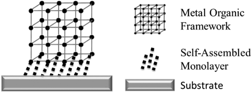 | ||
| Fig. 1 Schematic of a surface mounted MOF using a self-assembled monolayer to attach the MOF to the substrate. | ||
Experimental methods
Carbene synthesis and surface functionalization were done using adapted literature methods (Fig. 2).19,23 See ESI† for details about carbene synthesis (SI 1) and surface functionalization (SI 2). | ||
| Fig. 2 Scheme for Au–carbene SAM synthesis modified from the literature.25 | ||
The Cu-biphenyl dicarboxylic acid (Cu(bpdc)) surMOF was built using a layer by layer deposition method (Fig. 3). AFM, XPS, and grazing incidence XRD were used to confirm SAM formation, successful post-modification and surMOF deposition. Detailed surface characterization information is available in the ESI† (SI 3).
 | ||
| Fig. 3 Schematic of building SurMOF using layer-by-layer deposition. | ||
Results and discussion
Step 1: attachment of azide terminated SAM to Au substrate via carbene linkage
XPS was used to confirm the successful formation of the SAM via a carbene–Au linkage (SI 4 and Fig. SI 7, ESI†). The presence of an N 1s peak at 400.5 eV, with a residual of 1, matched the published N 1s binding energy for electron-rich azide nitrogen atoms.24 The C 1s region was fit to three peaks with a residual of 1.6. The C 1s peak at 284.8 eV was attributed to adventitious C and C–C and C–H bonds from the functionalizing molecule, the peak at 285.9 eV was attributed to a C–N bond and corresponded well to literature values of 286.0 eV,25 and the peak at 287.3 eV was attributed to the carbene species whose C 1s binding energy was shifted to higher binding energy due to bonding with two adjacent nitrogen atoms. The Au effects on shift to lower binding energy was minimal compared to the effect of the nitrogen atoms due to the greater electronegativity difference between N and C than Au and C, and less significantly, due to bonding with two N atoms versus bonding to only one Au atom. O 1s displayed a single peak, residual of 1, at 532.2 eV attributed to adventitious contamination.AFM after the next step of carboxylic acid modification was used to further confirm surface functionalization (SI 4 and Fig. SI 8, SI 9, ESI†). A decrease in RMS for height images from 10 on the bare sample to 3 nm on the modified substrate indicated greater uniformity attributed to SAM functionalization. Phase images displayed a visible change, with an increase of RMS to 16 from a RMS of 5 on the bare substrate indicating a greater variation in chemical composition due to surface functionalization.
Step 2: post-modification to form COOH terminated SAM
XPS was used to confirm the successful click chemistry post-modification of the SAM to alter the terminating group to a carboxylic acid (SI 4 and Fig. SI 10, ESI†). The C 1s region was fit to three peaks with a residual of 1.1 The 284.8 eV C 1s peak corresponded to adventitious C and C–C and C–H bonds from the sample, the 285.7 eV peak was from the C–N bond,25 and the 288.8 eV peak was attributed to the carboxylic acid carbon corresponding to literature values of 289.1 eV.26 The O 1s region displayed two peaks, at 530.4 eV and the one at 531.8 eV, as compared with the one peak of the azide terminated SAM, with a residual of 1.1. The peak at 531.8 eV corresponds well to the published26 carboxylic acid O shift of 532.0 eV (carbonyl) atoms. The N 1s region displayed three peaks at 401.8 eV, 400.1 eV, and 398.0 eV with a residual of 0.97. The 401.8 eV and 400.1 eV peaks were assigned, as with the azide terminated SAM, to the azide nitrogen atoms. The new peak at a lower binding energy was ascribed to the newly formed N–C bond of the triazole.24 Overall, the presence of a C 1s peak at 288.8 eV, two peaks in the O 1s region, and triazole presence in the N 1s region was in agreement to observed XPS binding energies in similar systems,19 confirming the success of the reaction. The presence of an azide peak in the C 1s and N 1s spectra indicated that the SAM was not completely converted to a –COOH terminated SAM.Step 3: formation of surMOF
XPS (SI 4 and Fig. SI 11, ESI†) and XRD (Fig. 4) measurements of samples post-surMOF attachment demonstrated successful surMOF synthesis. XPS of the Cu region displayed a peak fit with a residual of 1.6. The broad peak at 932.2 eV corresponded to literature values for Cu ion species, and the 940.9 eV peak was attributed to a Cu(II) shakeup peak.27 The O 1s region displayed a single peak at 532.3 eV, residual of 1.1, which conforms well to published O 1s values of 532.5 eV for broad peaks inclusive of –COOH and –COO− species.28 The C 1s region displayed two peaks with a residual of 1, with a large peak at 284.8 eV corresponding to adventitious C and C–C and C–H bonds from the surMOF molecules and a peak at 288.8 eV consistent with literature values for COO– and –COOH species.26 The C 1s peak did not indicate the presence of a C–N, however, that was likely due to a lack of resolution as nitrogen containing species were present in the N 1s region, which displayed a single peak at 398.2 eV, residual 1, attributed to the N–C bond of the triazole.27 The observation of this signal, which is normally weak, was likely due to the surMOF porosity and non-uniformity of the coverage which may allow for greater X-ray penetration and electron escape depth. Overall, the XPS spectra, particularly the presence of peaks in the Cu region, provides evidence of Cu and –COOH species.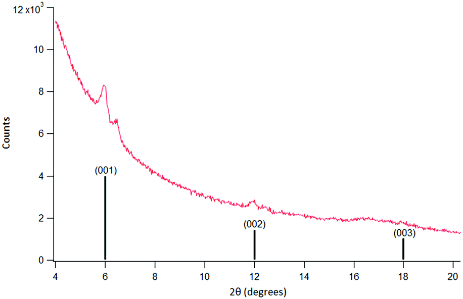 | ||
| Fig. 4 Measured data (red, top) (Cu Kα 1.5418 Å) and line representation of published XRD data (black, bottom) for out of plane reflection for tetragonal P4 structure identified for Cu(bpdc) in ref. 14. The set of larger peaks in the experimental data matched the literature patterns. The set of small peaks is due to the formation of a second crystalline structure which appeared after several hours of XRD data collection. | ||
XRD measurements confirmed the molecules were deposited in an organized surMOF structure. The XRD spectra displayed large peaks around 2θ values of 6 and 12, and a broad peak stretching from 17–18 2θ (Fig. 4) which matched previously published peak values for a Cu(bpdc) surMOF with three peaks around 2θ values of 6, 12, and 18.14 A second set of smaller peaks at 2θ values of 6.5, 12.4, and 17–18 appeared after several hours of scanning and were likely due to XRD induced changes in the surMOF material.
Noticeable changes in the surface appearance were visible by eye post-XRD in the exposed region. While initially attributed to structural decomposition, the appearance of smaller peaks at 6.5, 12.4 and 17–18 2θ peaks during later scan times suggested the visible change may be due to the formation of a second, ordered crystalline structure on the surface. ATR-FTIR on both XRD and non-XRD exposed regions of the same sample (SI 4 and Fig. S 12, ESI†) further show that the XRD exposed region displayed a peak at 2921 cm−1, which corresponds to the presence of hydrocarbon species. As data was acquired from the same sample, the results indicate the presence of a new species rather than adsorption of adventitious molecules onto the surface or into the MOF over the course of the overnight scans. A change in the chemical composition of the surMOF or integration of a newly formed species diffusion limited to the local area would lead to a new set of weaker peaks in the XRD spectra. This may be of interest to explore in future work.
AFM images (SI 4 and Fig. SI 13, ESI†) were obtained to gain an understanding of the surMOF structure. Interestingly, the AFM displayed irregularly shaped islands with phase images indicating that the borders of the surMOF islands differ in chemical composition from the center.
Conclusions
A novel Au mounted surMOF was successfully synthesized using a carbene linkage and layer by layer surMOF deposition methods. AFM, XPS and XRD results suggest the successful formation of the surMOF. The results of this study indicate that the change in SAM morphology did not affect the successful formation of the surMOF and its morphology. The synthetic method demonstrated in this work is highly versatile as there are many choices for metal terminations and MOF structures. The interchangeability of the carbene-based layer-by-layer surMOF components makes them useful in a wide variety of future studies. Longer XRD scan times resulted in diffraction patterns suggesting the presence of a second crystalline phase as a result of X-ray irradiation. This unexpected result may be of interest for exploration in future work.Conflicts of interest
There are no conflicts to declare.Acknowledgements
This work was partially supported by the National Science Foundation, Division of Chemistry, CHE-1213216, the Division of Materials Research, DMR-1506989. EF and TWS acknowledges the support of NSF-GRFP for funding.References
- O. M. Yaghi, G. Li and H. Li, Nature, 1995, 378, 703 CrossRef CAS.
- O. K. Farha, I. Eryazici, N. C. Jeong, B. G. Hauser, C. E. Wilmer, A. A. Sarjeant, R. Q. Snurr, S. B. T. Nguyen, O. Yazaydin and J. T. Hupp, J. Am. Chem. Soc., 2012, 134, 15016 CrossRef CAS PubMed.
- S. M. Cohen, Chem. Rev., 2012, 112, 970 CrossRef CAS PubMed.
- (a) H. Zhou, J. R. Long and O. M. Yaghi, Chem. Rev., 2012, 112, 673 CrossRef CAS PubMed; (b) J. R. Long and O. M. Yaghi, Chem. Soc. Rev., 2009, 38, 1201 RSC; (c) S. Kitagawa and H. C. Zhou, Chem. Soc. Rev., 2014, 43, 5415 RSC; (d) O. Shekhah, J. Liu, R. A. Fischer and C. Wöll, Chem. Soc. Rev., 2011, 40, 1081 RSC.
- BASF, Chem. Soc. Rev., 2014, 43, 6173 RSC.
- R. B. Getman, Y. Bae, C. E. Wilmer and R. Q. Snurr, Chem. Rev., 2012, 112, 703 CrossRef CAS PubMed.
- Y. Bai, Y. Dou, L. Xie, W. Rutledge, J. Li and H. Zhou, Chem. Soc. Rev., 2016, 45, 2327 RSC.
- Y. Liu, A. J. Howarth, N. A. Vermeulen, S. Y. Moon, J. T. Hupp and O. K. Farha, Coord. Chem. Rev., 2016, 346, 101 CrossRef.
- J. R. Li, J. Sculley and H. C. Zhou, Chem. Rev., 2012, 112, 869 CrossRef CAS PubMed.
- S. Wuttke, S. Braig, T. Preis, A. Zimpel, J. Sicklinger, C. Bellomo, J. O. Radler, A. M. Vollmar and T. Bein, Chem. Commun., 2015, 51, 15752 RSC.
- MOF Technologies Announces World's First Commercial Application of Metal Organic Framework Technology by Decco Worldwide at MOF 2016. Published 09/13/2016, http://www.moftechnologies.com/2016/09/13/mof-announces-worlds-first-commercial-application-decco-worldwide-mof-2016/2017.
- V. Stavila, A. A. Talin and M. D. Allendorf, Chem. Soc. Rev., 2014, 43, 5994 RSC.
- P. Falcaro, R. Ricco, C. M. Doherty, K. Liang, A. J. Hill and M. J. Styles, Chem. Soc. Rev., 2014, 43, 5513 RSC.
- J. Liu, B. Lukose, O. Shekhah, H. K. Arslan, P. Weidler, P. H. Gliemann, S. Brase, S. Grosjean, A. Godt, X. Feng, K. Mullen, I. B. Magdau, T. Heine and C. Wöll, Nat. Sci. Rep., 2012, 2, 1 Search PubMed.
- S. Hermes, F. Schroder, R. Chelmowski, C. Wöll and R. A. Fischer, J. Am. Chem. Soc., 2005, 127, 13744 CrossRef CAS PubMed.
- H. Gliemann and C. Wöll, Mater. Today, 2012, 15, 110 CrossRef CAS.
- E. P. Valadez Sánchez, H. Gliemann, K. Haas-Santo, C. Wöll and R. Dittmeyer, Chem. Ing. Tech., 2016, 88, 1798 CrossRef.
- T. M. Willey, A. L. Vance, T. van Buuren, C. Bostedt, L. J. Terminello and C. S. Fadley, Surf. Sci., 2005, 576, 188 CrossRef CAS.
- C. M. Crudden, J. H. Horton, I. I. Ebralidze, O. V. Zenkina, A. B. McLean, B. Drevniok, Z. She, H. Kraatz, N. J. Mosey, T. Seki, E. C. Keske, J. D. Leake, A. Rousina-Webb and G. Wu, Nat. Chem., 2014, 6, 409 CrossRef CAS PubMed.
- (a) A. Geuther and M. Hermann, Liebigs Ann. Chem., 1855, 95, 211 CrossRef; (b) P. de Frémont, N. Marion and S. P. Nolan, Coord. Chem. Rev., 2009, 253, 862 CrossRef.
- (a) A. Igau, H. Grützmacher, A. Baceiredo and G. Bertrand, J. Am. Chem. Soc., 1988, 110, 6463 CrossRef CAS; (b) A. J. Arduengo, R. L. Harlow and M. A. Kline, J. Am. Chem. Soc., 1991, 113, 361 CrossRef CAS; (c) W. A. Herrmann, Angew. Chem., Int. Ed., 2002, 41, 1290 CrossRef CAS; (d) E. Peris and R. H. Crabtree, Coord. Chem. Rev., 2004, 248, 2239 CrossRef CAS.
- G. Wang, A. Rahling, S. Amirjalayer, M. Knor, J. B. Ernst, C. Richter, H. Gao, A. Timmer, H. Gao, N. L. Doltsinis, F. Glorius and H. Fuchs, Nat. Chem., 2017, 9, 152 CrossRef CAS PubMed.
- (a) O. V. Starikova, G. V. Dolgushin, L. I. Larina, P. E. Ushakov, T. N. Komarova and V. A. Lopyrev, Russ. J. Org. Chem., 2003, 39(10), 1467 CrossRef CAS; (b) J. Andersen, U. Madsen, F. Björkling and X. Liang, Synlett, 2005, 2209 CAS.
- T. Heinrich, C. H. Traulsen, E. Darlatt, S. Richter, J. Poppenberg, N. L. Traulsen, I. Linder, A. Lippitz, P. M. Dietrich, B. Dib, W. E. S. Unger and C. A. Schalley, RSC Adv., 2014, 4, 17694 RSC.
- B. Kumar, M. Asadi, D. Pisasale, S. Sinha-Ray, B. A. Rosen, R. Haasch, J. Abiade, A. L. Yarin and A. Salehi-Khojin, Nat. Commun., 2013, 4, 2819 CrossRef.
- C. M. Whelan, J. Ghijsen, J. Pireaux and K. Maex, Thin Solid Films, 2004, 464, 388–392 CrossRef.
- M. C. Biesinger, L. W. M. Lau, A. R. Gerson and R. S. C. Smart, Appl. Surf. Sci., 2010, 257, 887 CrossRef CAS.
- T. A. Daniel, S. Uppili, G. McCarty and D. L. Allara, Langmuir, 2007, 23, 638 CrossRef CAS PubMed.
Footnotes |
| † Electronic supplementary information (ESI) available: Detailed experimental methods for carbene synthesis (SI 1), surface functionalization (SI 2), and surface characterization (SI 3). XPS, AFM and ATR-FTIR experimental data can be found in SI 4. XPS data includes spectra of the sample after SAM formation, after click modification of the SAM to alter the terminating group to a carboxylic acid, and after surMOF deposition. AFM images obtained after carboxylic acid modification and after surMOF formation. ATR-FTIR spectra of sample after XRD (PDF). See DOI: 10.1039/c8qm00527c |
| ‡ Present address: Department of Chemistry and Biochemistry, University of California, San Diego, La Jolla, California, 92093, USA. |
| § Present address: X-ray Science Division, Argonne National Laboratory, Argonne, IL, 60439, USA. |
| This journal is © the Partner Organisations 2019 |