 Open Access Article
Creative Commons Attribution 3.0 Unported Licence
Development of a tubular continuous flow reactor for the investigation of improved gas–solid interaction in photocatalytic CO2 reduction on TiO2
Martin
Dilla
a,
Ahmet E.
Becerikli
a,
Alina
Jakubowski
a,
Robert
Schlögl
ab and
Simon
Ristig
 *a
*a
aMax Planck Institute for Chemical Energy Conversion, 45470 Mülheim an der Ruhr, Germany. E-mail: simon.ristig@cec.mpg.de
bFritz Haber Institute of the Max Planck Society, 14195 Berlin, Germany
First published on 22nd January 2019
Abstract
A self-made, low-cost tubular reactor for the gas-phase photocatalytic CO2 reduction was developed. The resulting flow conditions cause an intensive interaction between the reactants in the gas-phase and the fixed bed photocatalyst. This approach is used to test the scalability of tubular reactors for the photocatalytic CO2 reduction.
The photocatalytic CO2 reduction to CH4 is associated with the transfer of eight electrons, the cleavage of two C–O double bonds and the formation of four C–H bonds (1). In order to provide a source of electrons and hydrogen it is desirable to oxidize H2O (2). Due to the extreme stability of the reactants CO2 and H2O, the conversion to CH4 and O2(3) is strongly endergonic (ΔG0 = +818 kJ mol−1). Therefore the photocatalytic CO2 reduction is a highly complex and thermodynamically challenging process and a photocatalyst which can run this process effectively has not been developed, yet.1
| Reduction: CO2 + 8H+ + 8e− → CH4 + 2H2O | (1) |
| Oxidation: 2H2O → O2 + 4H+ + 4e− | (2) |
 | (3) |
One of the most prominent materials for research on photocatalytic CO2 reduction is TiO2.2–4 The examination of kinetic barriers or the structure–function relationship of TiO2 is often limited. This is due to the low activity in product formation, the detection limit of many standard analytical methods and reaction conditions due to inadequate reactor designs.5 For this reason, the photocatalytic CO2 reduction is still not well understood.6–9 In order to prove if this complicated reaction proceeds, a reactor set-up needs to be developed which allows performing light induced experiments under optimal conditions. For such a design the illuminated fraction of the surface area should be maximized to realize adequate excitation of the photocatalyst, since the penetration depth of UV light with a wavelength of, for instance, 355 nm into TiO2 (anatase) is stated as ∼280 nm![[thin space (1/6-em)]](https://www.rsc.org/images/entities/char_2009.gif) 10 which is extremely low. In this way only a very small fraction of TiO2 will be excited by photons. Another important prerequisite is that experiments can be performed under optimal mass transport conditions of reactants and products, necessitating an intensive interaction between the gas-phase and the solid photocatalyst. One approach to meet these demands is the construction of a reactor with tubular geometry. A successful application of such a reactor design in photocatalytic research has already been reported for the oxidation of, for instance, organic compounds11–13 in liquid phase or NO214 in the gas phase, employing quartz glass12–14 and fluorinated-ethylene-propylene (FEP)11 as reactor materials. There are however no reports on the application of a tubular reactor geometry for photocatalytic gas phase CO2 reduction on solid state photocatalysts, e.g. TiO2. The feasibility to design such a reactor and utilize it for studying this highly complex reaction is reported here for the first time. To achieve reaction conditions of highest purity, an experimental procedure was developed for the removal of carbonaceous impurities from the surface of the sample prior to testing the photocatalytic activity in CO2 reduction. This is crucial, as residual impurities can contribute to the product formation in the CO2 reduction reaction, which leads to a significant overestimation of the activity. Only after successful removal it can be guaranteed that product formation originates from the reactants. With this set-up it was possible to conduct photocatalytic CO2 reduction on TiO2 with intensive interaction of the reactants and the solid photocatalyst under high-purity conditions.
10 which is extremely low. In this way only a very small fraction of TiO2 will be excited by photons. Another important prerequisite is that experiments can be performed under optimal mass transport conditions of reactants and products, necessitating an intensive interaction between the gas-phase and the solid photocatalyst. One approach to meet these demands is the construction of a reactor with tubular geometry. A successful application of such a reactor design in photocatalytic research has already been reported for the oxidation of, for instance, organic compounds11–13 in liquid phase or NO214 in the gas phase, employing quartz glass12–14 and fluorinated-ethylene-propylene (FEP)11 as reactor materials. There are however no reports on the application of a tubular reactor geometry for photocatalytic gas phase CO2 reduction on solid state photocatalysts, e.g. TiO2. The feasibility to design such a reactor and utilize it for studying this highly complex reaction is reported here for the first time. To achieve reaction conditions of highest purity, an experimental procedure was developed for the removal of carbonaceous impurities from the surface of the sample prior to testing the photocatalytic activity in CO2 reduction. This is crucial, as residual impurities can contribute to the product formation in the CO2 reduction reaction, which leads to a significant overestimation of the activity. Only after successful removal it can be guaranteed that product formation originates from the reactants. With this set-up it was possible to conduct photocatalytic CO2 reduction on TiO2 with intensive interaction of the reactants and the solid photocatalyst under high-purity conditions.
For this design it is mandatory that the material of the tubular reactor is transparent and chemically stable under illumination with UV light as well as mechanically flexible. Furthermore, the diameter of the tube must be as small as possible to increase the illuminated portion of the photocatalyst surface. One material which seems to fulfill these requirements is fluorinated ethylene propylene (FEP). The FEP tube chosen for the approach presented here has an inner diameter of 2.1 mm. To realize illumination of the photocatalyst with a centered light source, the FEP tube was wrapped around a self-made high intensity UV-LED bar. The UV light source consists of a square aluminum bar with three high power UV-LEDs (365 nm) on each side of the bar, amounting to a total of 12 UV-LEDs with a combined output power of 10 W (Fig. 1). Aluminum cooling fins and a high-performance cooling fan (90 m3 h−1) were installed to dissipate the emerging heat (Fig. 1) of the LEDs under operation. The light source is positioned in the center of a PTFE tube with an inner diameter of 6 cm to direct the cooling air flow along the whole bar (Fig. 1). The tubular reactor is wrapped equidistantly to the UV-LED bar along the inner wall of the PTFE (Fig. 1). The inlet of the reactor is connected to the gas supply to realize purging with He 6.0 (99.9999% purity) and dosing of the reactant gas mixture (7000 ppm CO2 in He 6.0). The outlet of the reactor is connected to a Shimadzu Tracera GC 2010 Plus. This GC is equipped with a barrier discharge ionization detector (BID), which allows quantifying CO2, CO, CH4, C2H6, H2O, O2 and H2 in the 0.1 ppm range. Based on this high sensitivity, the BID is a suitable analytical device for an application in continuous-flow photocatalytic CO2 reduction. Swagelok fittings were used for all tube connections.
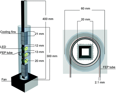 | ||
| Fig. 1 Illustration of the self-made high intensity UV-LED bar equipped with a fan and attached cooling fins. Left side: Front view. Right side: On-top view. | ||
To verify that the FEP tube does not release any carbon-containing species upon UV light irradiation which can be misleadingly counted as products, a blank experiment with an empty tube reactor was performed (Fig. 2).
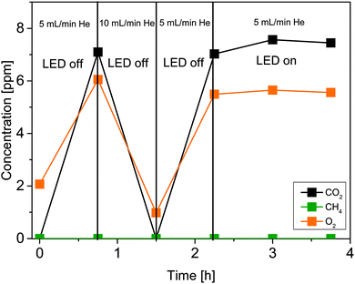 | ||
| Fig. 2 Stability of the FEP tube under illumination with UV light. Illumination takes place from 2.25 h to 3.75 h. | ||
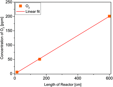
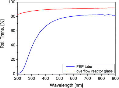
After flushing out the remaining atmospheric air inside the reactor with He (50 mL min−1), the flow rate was decreased to 5 mL min−1 (0 h, Fig. 2). Then the gas flow was held for 0.75 h. In this period of time the concentration of CO2 and O2 increased. From 0.75 to 1.5 h the He flow rate was increased to 10 mL min−1 and a decrease in the concentration of both species was observed as a consequence of the higher dilution with inert gas. In the following, the gas flow was decreased again to 5 mL min−1. It can be seen that the concentration of CO2 and O2 from 0.75 h can be reproduced at 2.25 h. Due to the absence of illumination it is assumed that environmental CO2 and O2 diffused through the tube walls. Starting from 2.25 h the UV illumination was initiated. No significant release of CO2 and CH4 was observed under the influence of UV light. Furthermore, the presence of CO, H2 and C2H6 (not shown in Fig. 2) can be excluded. This result shows that the FEP tube is physicochemically stable against UV light irradiation, thus its use is suitable for the purpose of this work. However, since we know from our previous work15 that O2 inhibits the photocatalytic CO2 reduction, it was decided to study the diffusion properties of the FEP tube in detail. More specifically the amount of incoming O2 as a function of the tube length reactor. An increase of the O2 concentration by 0.33 ppm cm−1 of reactor was determined from the slope of the linear fit (Fig. 3, red line). Most likely diffusion of O2 from air is the reason for this observation. To verify the UV-transparency of the reactor material, the relative transmission of the FEP tube was determined via UV-Vis spectroscopy (Fig. 4, blue line). At 365 nm, the emitted wavelength of the UV-LEDs, the relative transmission is 60%. This indicates that a significant fraction of the light intensity does not reach the photocatalysts surface, likely due to absorption and scattering phenomena. As the absorption of photons by the FEP tube could result in heating of the reactor, the temperature inside the tube under photocatalytic reaction conditions was determined, since thermal energy was found to influence the activity in CO2 reduction on TiO2.16
Consequently, a thermocouple was placed in a fixed bed of TiO2 (P25) in the FEP tube. In the temperature profile in Fig. 5 it can be seen that the temperature inside the reactor increases from 23.1 to 26.2 °C under the applied illumination conditions. Hence, the air stream inside the PTFE tube seems to be sufficient to keep the reactor temperature close to room temperature.
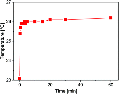 | ||
| Fig. 5 Temperature profile inside the fixed bed of P25 in the FEP tube during illumination with the LED bar. | ||
After verification of the suitability of the reactor material and setting the optimum experimental conditions at which the set-up can be used for the photocatalytic CO2 reduction, two tube reactors were prepared with P25 as photocatalyst. Previously, the P25 sample was calcined at 400 °C for 3 h. This pretreatment allows a first oxidative removing of carbonaceous impurities. The sample was pressed and sieved and the mesh size 0.28 mm fraction was filled into the tube using a funnel.
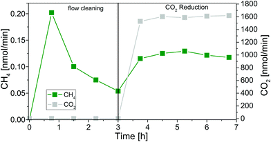
A small plug of glass wool at the reactor outlet and inlet kept the fixed bed in the reactor. For testing the set-up, reactors with lengths of 14 and 26 cm were prepared and filled with 223 and 680 mg of P25, respectively. In Fig. 6 the formation of CH4 in the cleaning procedure and the CO2 reduction with the 26 cm reactor is shown exemplarily.
To flush out the remaining air inside the FEP tube, the reactor was purged with He (50 mL min−1) for 30 min. Subsequently, remaining carbonaceous impurities were removed during the flow cleaning procedure (5 mL He min−1) under UV irradiation (Fig. 6). Since the powder was in contact with ambient air during the sample filling, the P25 sample was expected to be covered by multilayers of physisorbed water.17 GC measurements were carried out every 45 min to monitor the cleaning progress.
The duration of the cleaning procedure depends on the concentration of carbon-containing species on the photocatalyst. The products of the cleaning procedure are CH4 and CO2. As shown in our previous reports,15 CH4 originates from hydrogenation of carbon-containing impurities and from the photocatalytic reduction of trace amounts of CO2 in the He purging gas. The photocatalytic CO2 reduction experiment is started as soon as the CH4 concentration is almost constant. Then it is assumed that all carbonaceous species are removed and CH4 is formed from CO2 in the He purge gas. For both reactors the CO2 reduction is initiated after 3 h of photocatalytic cleaning (Fig. 6) by changing the gas flow from pure He to the reactant gas mixture (7000 ppm CO2 in He, optimal reactant concentration in previous studies15,16). The flow rate of 5 mL min−1 is maintained and the UV illumination is continued without interruption. No additional H2O is dosed to the reactor since we verified in previous experiments that continuous dosing of H2O can lower the activity of P25 in the CO2 reduction reaction due to competitive adsorption phenomena and occupation of active sites.16 The present amounts of H2O on P25 are sufficient to run the CO2 reduction for the desired timeframe.16 It becomes obvious from Fig. 6 that the CH4 flow rate increases when CO2 is dosed to the tubular reactor.
In Table 1 the overall formation rates of CH4 with the 14 and 26 cm reactor are shown. Since the activity of the photocatalytic reaction is dependent on the amount of exposed surface area, it becomes clear that the activity scales with the length of the reactor and the amount of TiO2, respectively. However, it is obvious that the correlation with the formation rates is not linear, most likely due to differences in the illumination conditions and the sample filling. The obtained concentrations of O2 displayed in Table 1 correspond to the linear fit in Fig. 3. The results also indicate that there is no increased inhibitive effect which scales with the reactor length and thus the higher amounts of O2.
| 14 cm | 26 cm | |
|---|---|---|
| Overall CH4 formation rate/nmol h−1 | 1.4 | 3.6 |
| O2 concentration (end of reactor)/ppm | 4.7 | 13 |
To investigate the performance of the tubular reactor setup, photocatalytic CO2 reduction was also conducted with an overflow reactor. The results are then compared to those from the 14 cm reactor. A detailed description of the overflow reactor geometry was made by Mei et al.18 In this all-stainless steel reactor design, the catalyst is illuminated from above through the quartz reactor lid with a UV-LED (0.82 W output). The reactants only pass the surface of a fixed bed of 70 mg pre-cleaned P25 resulting in a significantly less intensive interaction between the gas-phase and the photocatalyst. Due to the O2 permeability of the FEP tube it was decided to use the experimental results obtained with the smaller tube for a comparison with the overflow reactor. In this way similar reaction conditions are established, except for the gas–solid interaction. This comparison is the basis for an evaluation of the effect of the gas–solid interaction on the activity of photocatalytic CO2 reduction on TiO2.
The formation rates of CH4 obtained in this study from both different reactor designs are shown in Table 2. The rates are related to the mass of P25 (gcat) and the geometric illuminated area to evaluate the effect of the illumination conditions and the gas–solid interaction, respectively. Only the fraction of surface area which is directly illuminated was considered to be the geometric surface, i.e. the half of the inner tube surface and the bottom size of the overflow reactor. It can be clearly seen that the overflow reactor shows a higher CH4 formation rate related to the mass of P25 (Table 2). Most likely a large mass fraction of P25 inside the tube is not illuminated due to the small penetration depth of UV light, the tubular geometry and the arrangement of illumination. Consequently, only a minor amount of photocatalyst is excited. This result clearly shows that the activity in the photocatalytic CO2 reduction reaction is strongly dependent on the illuminated fraction of the surface area. For comparison of the rates related to the geometric illuminated area it needs to be stressed that the transmission of the overflow reactor lid (89% at 365 nm, Fig. 4) exceeds that of the FEP reactor. Although the same kind of UV LED is used for the two reactor types, the light intensity impinging on the exposed surface of the photocatalyst will be lower for the FEP reactor. Still, the comparison of the rates related to the geometric illuminated area reveals a higher activity for the tubular reactor, although the light intensity is lower. It verifies that the improved gas–solid interaction in the tubular reactor is beneficial for the activity in photocatalytic CO2 reduction.
| Tube reactor | Overflow reactor | |
|---|---|---|
| rCH4/nmol cm−2 h−1 | 0.42 | 0.26 |
| rCH4/nmol gcat−1 h−1 | 6.3 | 23 |
Conclusions
This study shows the successful development of a scalable tubular reactor for the gas-phase photocatalytic CO2 reduction on TiO2. For the development of new reactor geometries for the photocatalytic CO2 reduction it is essential that the illuminated fraction of photocatalyst is maximized and the interaction of the reactants in the gas-phase with the photocatalyst is intensive. In general, a tubular reactor geometry is an appropriate choice to overcome the abovementioned problems. However, with respect to the O2 diffusion properties, FEP as material appears to be less applicable for the scalability as a photoreactor for the photocatalytic CO2 reduction, as an inhibition of the product formation due to increased amounts of O2 in the reactor might occur for elongated reactors. While the reactor design certainly has its limitations in photocatalytic CO2-reduction, its simple and scalable design might be very interesting for other groups examining different photocatalytic reactions or materials. A suggested alternative could be quartz glass, as it is transparent to UV light and prevents the diffusion of O2 into the reactor from the environment. The utilization of quartz capillaries would provide intensive gas–solid interaction and the small inner diameter would improve the illumination conditions. Furthermore, the reactor can be arranged in a centered geometry relative to the light source. This will result in the illumination of the whole tube and an improved UV excitation of the photocatalyst.Conflicts of interest
There are no conflicts to declare.Acknowledgements
Open Access funding provided by the Max Planck Society.Notes and references
- G. Mul, C. Schacht, W. P. M. van Swaaij and J. A. Moulijn, Functioning devices for solar to fuel conversion, Chem. Eng. Process., 2012, 51, 137 CrossRef CAS.
- J. Li and N. Wu, Semiconductor-based photocatalysts and photoelectrochemical cells for solar fuel generation: a review, Catal. Sci. Technol., 2015, 5, 1360 RSC.
- S. N. Habisreutinger, L. Schmidt-Mende and J. K. Stolarczyk, Photocatalytic reduction of CO2 on TiO2 and other semiconductors, Angew. Chem., Int. Ed., 2013, 52, 7372 CrossRef CAS PubMed.
- E. V. Kondratenko, G. Mul, J. Baltrusaitis, G. Larrazabal and J. Perez-Ramirez, Status and perspectives of CO2 conversion into fuels and chemicals by catalytic, photocatalytic and electrocatalytic processes, Energy Environ. Sci., 2013, 6, 3112 RSC.
- A. Pougin, M. Dilla and J. Strunk, Identification and exclusion of intermediates of photocatalytic CO2 reduction on TiO2 under conditions of highest purity, Phys. Chem. Chem. Phys., 2016, 10809 RSC.
- I. A. Shkrob, T. W. Marin, H. He and P. Zapol, Photoredox reactions and the catalytic cycle for carbon dioxide fixation and methanogenesis on metal oxides, J. Phys. Chem. C, 2012, 116, 9450 CrossRef CAS.
- C. Amatore and J.-M. Savéant, Mechanism and kinetic characteristics of the electrochemical reduction of carbon dioxide in media of low proton availability, J. Am. Chem. Soc., 1981, 1981, 5021 CrossRef.
- D. Lee and Y. Kanai, Role of four-fold coordinated titanium and quantum confinement in CO2 reduction at titania surface, J. Am. Chem. Soc., 2012, 134, 20266 CrossRef CAS PubMed.
- I. A. Shkrob, N. M. Dimitrijevic, T. W. Marin, H. He and P. Zapol, Heteroatom-transfer coupled photoreduction and carbon dioxide fixation on metal oxides, J. Phys. Chem. C, 2012, 116, 9461 CrossRef CAS.
- H. Kim, R. C. Y. Auyeung, M. Ollinger, G. P. Kushto, Z. H. Kafafi and A. Pique, Laser-sintered mesoporous TiO2 electrodes for dye-sensitized solar cells, Appl. Phys. A, 2006, 83, 73 CrossRef CAS.
- D. Z. Dan, R. C. Sandford and P. J. Worsfold, Determination of chemical oxygen demand in fresh waters using flow injection with on-line UV-photocatalytic oxidation and spectrophotometric detection, Analyst, 2005, 130, 227 RSC.
- Y. C. Kim, S. Sasaki, K. Yano, K. Ikebukuro, K. Hashimoto and I. Karube, A flow method with photocatalytic oxidation of dissolved organic matter using a solid-phase (TiO2) reactor followed by amperometric detection of consumed oxygen, Anal. Chem., 2002, 74, 3858 CrossRef CAS.
- F. Moulis and J. Krýsa, Photocatalytic degradation of acetone and methanol in a flow-through photoreactor with immobilized TiO2, Res. Chem. Intermed., 2015, 41, 9233 CrossRef CAS.
- K. Chaisiwamongkhol, N. Manoyen, M. Suttiponparnit, D. Nacapricha, S. M. Smith and K. Uraisin, Development of gas flow reactor with on-line monitoring system for nitrogen dioxide removal, Microchem. J., 2017, 135, 199 CrossRef CAS.
- M. Dilla, R. Schlögl and J. Strunk, Photocatalytic CO2 reduction under continuous flow high-purity conditions: quantitative evaluation of CH4 formation in the steady-state, ChemCatChem, 2017, 9, 696 CrossRef CAS.
- M. Dilla, A. Mateblowski, S. Ristig and J. Strunk, Photocatalytic CO2 reduction under continuous flow high-purity conditions: influence of light intensity and H2O concentration, ChemCatChem, 2017, 9, 4345 CrossRef CAS.
- M. A. Bañares and I. E. Wachs, Molecular structures of supported metal oxide catalysts under different environments, J. Raman Spectrosc., 2002, 33, 359 CrossRef.
- B. Mei, A. Pougin and J. Strunk, Influence of photodeposited gold nanoparticles on the photocatalytic activity of titanate species in the reduction of CO2 to hydrocarbons, J. Catal., 2013, 306, 184 CrossRef CAS.
| This journal is © The Royal Society of Chemistry and Owner Societies 2019 |

