
 Open Access Article
 This Open Access Article is licensed under a Creative Commons Attribution-Non Commercial 3.0 Unported Licence
Towards fast-charging technologies in Li+/Na+ storage: from the perspectives of pseudocapacitive materials and non-aqueous hybrid capacitors
Haijian
Huang
 and
Markus
Niederberger
*
and
Markus
Niederberger
*
Laboratory for Multifunctional Materials, Department of Materials, ETH Zürich, Vladimir-Prelog-Weg 5, 8093 Zürich, Switzerland. E-mail: markus.niederberger@mat.ethz.ch
First published on 18th September 2019
Abstract
Since the discovery of the pseudocapacitive behavior in RuO2 by Sergio Trasatti and Giovanni Buzzanca in 1971, materials with pseudocapacitance have been regarded as promising candidates for high-power energy storage. Pseudocapacitance-involving energy storage is predominantly based on faradaic redox reactions, but at the same time the charge storage is not limited by solid-state ion diffusion. Besides the search for pseudocapacitive materials, their implementation into non-aqueous hybrid capacitors stands for the strategy to increase power density by a rational design of the battery structure. Composed of a battery-type anode and a capacitor-type cathode, such devices show great promise to integrate the merits of both batteries and capacitors. Today, the availability of fast-charging technologies is of fundamental importance for establishing electric vehicles on a mass scale. Therefore, from the perspective of materials and battery design, understanding the basics and the recent developments of pseudocapacitive materials and non-aqueous hybrid capacitors is of great importance. With this goal in mind, we introduce here the fundamentals of pseudocapacitance and non-aqueous hybrid capacitors. In addition, we provide an overview of the latest developments in this fast growing research field.
1. Introduction
In light of the rising environmental issues, developing benign sustainable energy storage technologies has become a global priority. Reflecting its importance, massive efforts from the academic as well as from the industry side have been devoted to the development of Li-ion battery (LIB) technology over the years.1,2 From microchips to electric vehicles (EVs), LIBs have been tremendously successful as an efficient power source.3 Particularly, the role of LIBs in enabling the replacement of fossil-fuelled vehicles by EVs was highlighted in order to reduce the consumption of oil resources and the generation of CO2 gases.2 However, to achieve a leap-forward development in the field of LIBs several challenges have to be overcome.Extensive efforts have also been devoted to developing post-Li-ion-battery technologies such as Li–metal batteries,4,5 Li–S batteries,6,7 and Li–O2 batteries7,8 mainly to boost the energy density of rechargeable batteries. However, also power density remains a technological issue. Recently, Cui et al. highlighted the importance of fast-charging technologies for the further promotion of EVs.9 In fact, when energy density is improved (while keeping the power density constant), also the charging time is prolonged (E = Pt, where E, P, and t correspond to energy, power, and time, respectively). As shown in Fig. 1a, the recharge time of EVs is on the order of tens of hours, almost 200 times longer than the refueling time of a gasoline car. The extremely long charging time of EVs poses a serious barrier for a wider market penetration. The fastest recharge rate achieved by Tesla vehicles is 120 kW, enabling a charging time of 30 min for 200 miles.9 However, compared to the quick refuelling experience (ca. 2 min) of conventional vehicles, this charging capability is still far behind the satisfactory level for the customers. Time is precious in the rush of modern life. High power conversion capability means saving a great amount of time. Flash charging technology will become an attractive feature of EVs and other energy storage devices, significantly strengthening their position in the market. In fact, developing rechargeable batteries with both high energy density and high power output has become one of the main challenges on the way to advanced energy storage devices.
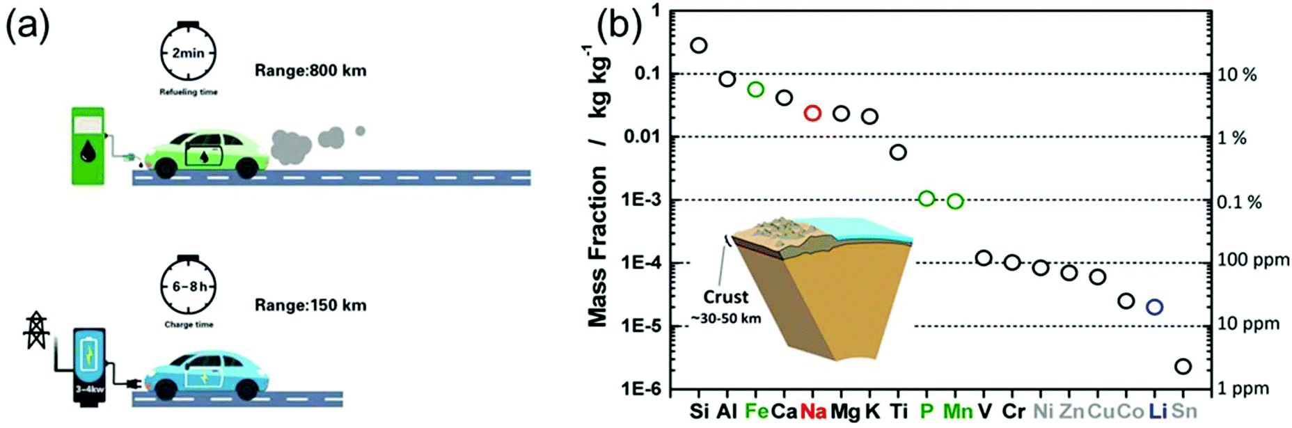 | ||
| Fig. 1 (a) Refuelling time and charging time of a gasoline car and an electric vehicle, respectively. (b) Elemental abundance in the Earth's crust. Reproduced with permission from ref. 16. Copyright 2014, American Chemical Society. | ||
In this review, mainly two topics will be addressed: (i) exploration of high-rate electrode materials, and (ii) rational design of the battery structure.
Regarding the first aspect, electrode materials with pseudocapacitive behaviour turned out to be particularly promising, because they are able to bridge the gap between a capacitor and a conventional battery electrode material. The charge storage mechanism is based either on surface/near-surface faradaic processes or on the fast ion intercalation into tunnels or layers of a redox-active material.10
Concerning the rational design of battery structures, efforts have been put into the development of hybrid capacitors, in which a battery-type electrode is combined with a capacitor-type electrode to overcome the energy density limitation of conventional electrochemical capacitors.11,12 When mentioning hybrid capacitors, two systems are usually involved, i.e., aqueous hybrid capacitors and non-aqueous hybrid capacitors. Non-aqueous hybrid capacitors using a non-aqueous electrolyte usually have a higher energy density than aqueous ones due to the high operating voltage.12–15 Accordingly, this minireview mainly focuses on non-aqueous systems.
In spite of the progress, which has been made towards high-power energy storage devices, the rapid development of EVs and advanced smart phones has massively accelerated the need for fast charging technologies. Thus, exploration of novel pseudocapacitive materials in combination with advanced non-aqueous hybrid capacitors with high power density and high energy density remains in the focus of academic and industrial research.
On the other side, the increasing market share of electronic devices and EVs/hybrid EVs has put Li production under pressure. Not only is the abundance of Li on the earth quite limited (only about 20 ppm in the earth's crust,16Fig. 1b), but the export policies of the corresponding countries can vary quickly.16,17 Na-ion batteries (NIBs), although under investigation since the 1970s and thus as long as LIBs, almost disappeared in the following three decades, because most of the efforts were devoted to the development of LIBs. However, the cost per kW h of energy that Na can provide is much lower than that of Li, moving NIBs back into the centre of interest, especially for large-scale applications.16–18 Unfortunately, the large ionic radius of Na usually leads to sluggish ion diffusion kinetics, considerably hampering the development of electrode materials with not only high energy density, but also good rate capability.19 Thus, on the way to high-performance NIBs, suitable electrode materials with favorable ion storage kinetics have to be found.
Our minireview focuses on pseudocapacitive materials and non-aqueous hybrid capacitors for high-power Li+/Na+ storage. The content is divided into two sections. First, the theoretical background of pseudocapacitance and non-aqueous hybrid capacitors is discussed. Second, based on selected examples rather than an exhaustive literature survey we provide a general overview of the recent advances in pseudocapacitive materials and non-aqueous hybrid capacitors.
2. Pseudocapacitance
2.1. Basics of pseudocapacitance
Regarding power density, electric double-layer capacitors (EDLCs) possess a number of desirable properties compared to conventional batteries, including charging within seconds and long-term cycling stability. EDLCs have met with great interest since the first patent was released by General Electric in 1957.10,20 Due to their extremely high power density, which can be up to 10 times that of rechargeable batteries, this type of devices has been successfully applied in many fields such as computer memory backup power, load lifting equipment, LED flash devices and so on.21,22 Electrostatic double layer charge storage in EDLCs generally occurs through the adsorption of electrolyte ions onto the surfaces of electrode materials with no faradaic reactions involved. High-surface-area carbon materials are often identified to behave in this manner due to their large amount of surface adsorption sites and extraordinary high electronic conductivity. However, due to the confinement to the electrode surface area, the energy densities of commercial EDLCs are limited to 3–6 W h kg−1,10 which are far below those of batteries (100–200 W h kg−1 for commercial LIBs). In this context, merging the merits of both EDLCs and rechargeable batteries represents a promising pathway to high-power and high-energy electrode materials.In the 1990s, Conway and co-workers proposed the concept of pseudocapacitance.23,24 Energy storage involving pseudocapacitance, which relies predominantly on faradaic redox reactions, while the charge storage is not limited by solid-state ion diffusion, occupies a middle ground between EDLCs and batteries.25 Generally, pseudocapacitance can be classified into three types:10 (i) monolayer adsorption pseudocapacitance, (ii) surface redox pseudocapacitance and (iii) intercalation pseudocapacitance (Fig. 2).
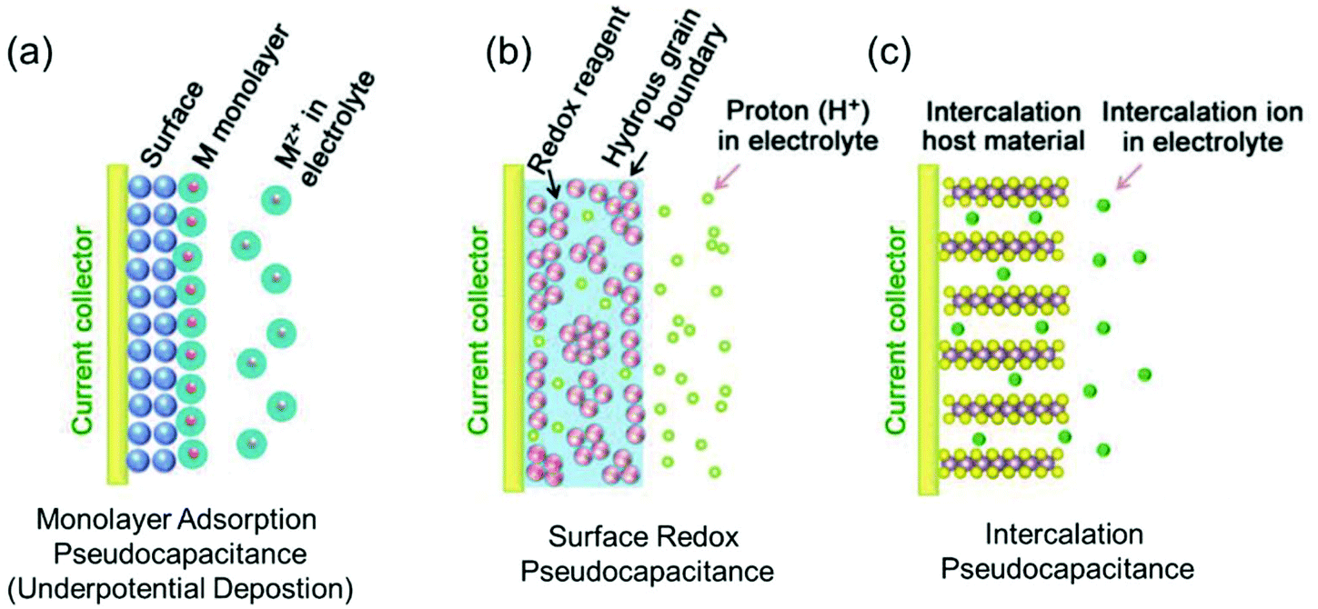 | ||
| Fig. 2 Different types of reversible redox mechanisms that give rise to pseudocapacitance: (a) monolayer adsorption pseudocapacitance (underpotential deposition), (b) surface redox pseudocapacitance, and (c) intercalation pseudocapacitance. Reproduced with permission from ref. 20. Copyright 2018, Wiley-VCH. | ||
The origin of monolayer adsorption pseudocapacitance mainly comes from the reversible surface electrochemisorption (Fig. 2a). A typical example is the deposition of Pb on Au.26 Due to the stronger interaction of Pb–Au compared with that of Pb–Pb in crystalline Pb metal, Pb can be deposited onto Au more easily than onto itself.26 Such a process is also referred to as underpotential deposition.
Surface redox pseudocapacitance occurs when alkali ions are electrochemically adsorbed onto the surface or near the surface of the electrode materials through charge-transfer processes (Fig. 2b). RuO2 was the first material found to demonstrate surface redox pseudocapacitive behavior. In 1971, Trasatti and Buzzanca discovered that the cyclic voltammogram (CV) curves of hydrous RuO2 were rectangular in shape, which is a characteristic feature of a capacitor. However, the charge storage processes (storage of protons in this case) in RuO2 were found to be of faradaic nature.27 Subsequent studies revealed that the pseudocapacitive charge storage behavior of RuO2 was a combination of the following factors: (a) the redox behavior of Ru4+, (b) the high electronic conductivity of RuO2, (c) short diffusion distances due to the large “outer surface” and (d) the large structural-water-induced “inner surface” in the porous hydrous RuO2.28,29
Intercalation pseudocapacitance arises, when the intercalation/deintercalation processes are not kinetically limited by the slow solid-state diffusion of the alkali ions in the crystal structure of the electrode materials on the time scale of interest (Fig. 2c). Compared with surface redox pseudocapacitance, which only occurs on or near the electrode surface, intercalation pseudocapacitance exists in the bulk.30 A clear example is the pseudocapacitance in T-Nb2O5.30 Through investigation of the electrochemical features of T-Nb2O5, Dunn and co-workers proved that the crystal structure of T-Nb2O5 allowed pathways for ion transport with low energy barriers and only negligible changes of the lattice constants during intercalation of Li+ into T-Nb2O5 when operating within a voltage window of 1.2–3.0 V.31,32 The CV measurements showed that the current was linearly proportional to the voltage sweep rate, and the capacity did not vary significantly with charging time even for bulk material. They demonstrated that for charging times as fast as 1 min, there were still no diffusion limitations in bulk T-Nb2O5.
2.2. Identification of pseudocapacitance
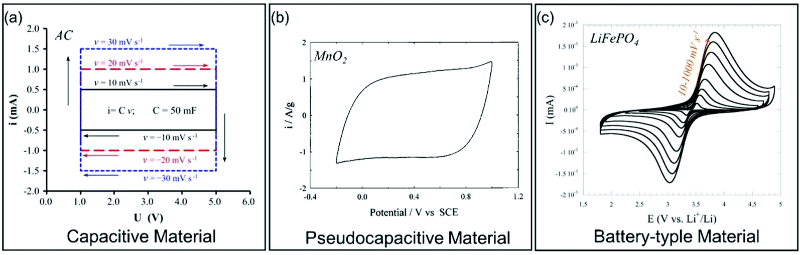
The charge storage in pseudocapacitive materials is faradaic in origin as in battery-type materials,33–35 although dQ/dV (Q and V represent charge and potential, respectively) derived from the charging/discharging curves corresponds to a capacitive behavior.13 Owing to the non-diffusion controlled ion storage processes, pseudocapacitive materials usually show higher rate capability than battery-type materials. Identification of pseudocapacitance can be carried out through the investigation of electrochemical features characteristic for pseudocapacitive materials using two techniques: (i) galvanostatic charge/discharge curves and (ii) potentiodynamic sweep CV measurements. Additionally, also phase transitions have to be considered. These three aspects will be discussed in the following sections.| Qc = CΔU | (1) |
| C = εrε0A/d | (2) |
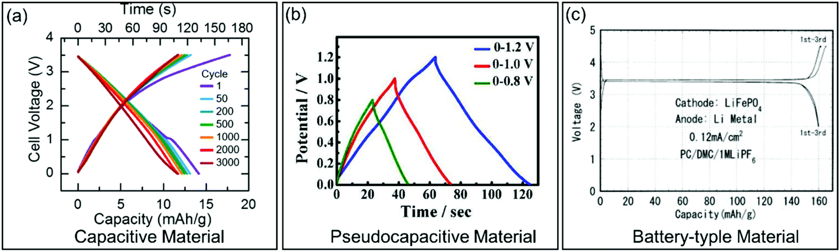 | ||
| Fig. 3 Galvanostatic charge/discharge curves for different types of electrode materials. (a) Carbon-based EC material. Reproduced with permission from ref. 36. Copyright 2017, Electrochemical Society. (b) Pseudocapacitive KxMnO2. Reproduced with permission from ref. 37. Copyright 2016, American Chemical Society. (c) Battery-type LiFePO4. Reproduced with permission from ref. 38. Copyright 2001, Electrochemical Society. | ||
| ic = dQ/dt = CdU/dt = Cv | (3) |
 | ||
| Fig. 4 Galvanostatic charge/discharge curves for different types of electrode materials. (a) Carbon-based EC material. Reproduced with permission from ref. 39. Copyright 2013, Elsevier. (b) Pseudocapacitive MnO2. Reproduced with permission from ref. 41. Copyright 1999, Elsevier. (c) Battery-type LiFePO4. Reproduced with permission from ref. 40. Copyright 2011, Electrochemical Society. | ||
Dunn and co-workers demonstrated that CV analysis can be further used to estimate the current contribution from pseudocapacitance through an appropriate experimental design.10,42 In fact, one can quantitatively separate the contributions from capacitive effects (fast surface/near-surface redox reactions or fast ion insertion) and slow diffusion-controlled processes through analyzing the dependence of the CV curves on the sweep rates. In CV measurements, the current response at a fixed potential (i(V)) can be expressed as the sum of the current contributions from the capacitive effects (ic) and the diffusion-controlled insertion reactions (id):42
| i(V) = ic + id | (4) |
According to eqn (3), ic is proportional to the sweep rate v (ic ∝ v). On the other hand, the contribution of the current id from the diffusion-limited processes is proportional to the square root of the voltage scan rate v according to the Rendle–Sevcik equation,43i.e., id ∝ v1/2. Therefore, eqn (4) can be transformed into:
| i(V) = k1v + k2v1/2 | (5) |
| i(V)/v1/2 = k1v1/2 + k2 | (6) |
Besides, in CV curves the peak current ip also obeys a power law relationship with the sweep rate v described as:
| ip = avb | (7) |
Eqn (7) can be further transformed to:
ln(ip) = ln![[thin space (1/6-em)]](https://www.rsc.org/images/entities/char_2009.gif) a + blnv a + blnv | (8) |
Here, a and b are adjustable parameters.30,42 The parameter b is determined by the slope of ln(v)–ln(i) plots. When b = 0.5, the peak current is proportional to the square root of the sweep rate (v1/2), indicating a diffusion-controlled faradaic process. At the other end, b = 1 represents a fully capacitive charge storage behavior, i.e., no diffusion limit. A typical example is the study of the pseudocapacitive effects of TiO2 by Dunn et al.42 Capacitive contributions of 55%, 35%, and 15% of the total lithium-ion storage were calculated for 7, 10, and 30 nm particle sizes, respectively, through the above CV analysis (Fig. 5a and b). In addition, b-values for the 10 nm TiO2 film were in the range of 0.8–1.0 at potentials higher or lower than the peak potential, indicating that the current is predominantly capacitive (Fig. 5c) at these potentials.
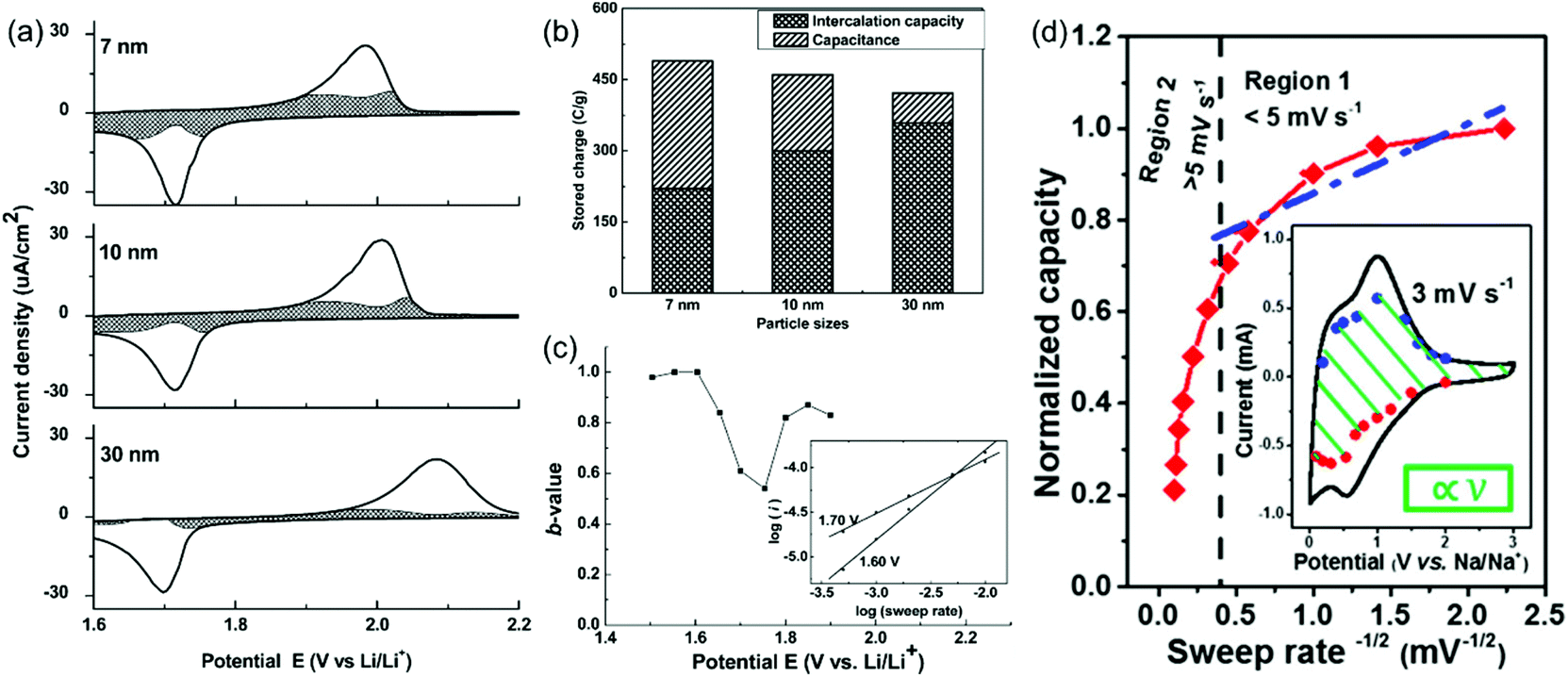 | ||
| Fig. 5 (a–c) CV analyses of TiO2 films. Reproduced with permission from ref. 42. Copyright 2007, American Chemical Society. (a) Voltammetric response (0.5 mV s−1) for 7 nm, 10 nm and 30 nm TiO2 films. (b) Comparison of the capacitive contributions in TiO2 nanoparticle films (0.5 mV s−1 sweep rate). (c) b-Values for the 10 nm film. (d) Plot of capacity vs. v−1/2 to separate diffusion-controlled and capacitive-controlled contributions in a mesoporous single-crystal-like TiO2@graphene nanocomposite. Reproduced with permission from ref. 45. Copyright 2017, American Chemical Society. | ||
Another method based on the relation between capacity Q and scan rate v, which was developed by Ardizzone et al.,44 is also suitable to differentiate capacitive and diffusion-controlled processes. The total stored charge Q can be separated into two parts, i.e., the capacitive contribution Qc and the diffusion-controlled contribution Qd:
| Q = Qc + Qd | (9) |
According to eqn (1), the capacitive contribution Qc is independent of the sweep rate v. The Qc value can be obtained at an infinite potential sweep rate (v → ∞), i.e., Qc = Qv=∞. On the other hand, Qd follows:
| Qd = idt | (10) |
| t = ΔU/v | (11) |
Therefore, t is proportional to v−1 (t ∝ v−1). As mentioned above, id contributed by the diffusion-limited processes is proportional to the square root of the sweep rate v (id ∝ v−2). Combining eqn (10) with eqn (9), it can be concluded that the stored charge Qd is expected to be limited by v−1/2. Accordingly, eqn (9) can be converted into:
| Q = Qv=∞ + kv−1/2 | (12) |
| Materials | Operating voltage window | |
|---|---|---|
| Intrinsic pseudoapacitive materials | RuO228 |
0–1 V vs. saturated calomel electrode (SCE) |
| MnO241 |
-0.2–1 V vs. SCE | |
| LiFeTiO452 |
1.5–4.8 V vs. Li/Li+ | |
| T-Nb2O530 |
1.2–3 V vs. Li/Li+ | |
| Ti3C2Tx MXene53 | -0.2–0.4 V vs. Ag/AgCl | |
| Extrinsic pseudocapacitive materials | LiCoO254 |
3–4.2 V vs. Li/Li+ |
| MoS255 |
0.8–3 V vs. Li/Li+ | |
| MoO249 |
1.1–3 V vs. Li/Li+ | |
| TiS250 |
1.5–3 V vs. Li/Li+ |
Consequently, identification of pseudocapacitance in electrode materials should be based on electrical and electrochemical considerations. Capacitor-like features shown in galvanostatic charge/discharge curves and in potentiodynamic sweep CV measurements are not sufficient proof for pseudocapacitance. Possible phase transitions within the voltage window also have to be taken into account. Only if dQ/dV is a constant value within the entire operating voltage window or approaches a constant value, can the material be described as pseudocapacitive.
3. Non-aqueous hybrid capacitors
In comparison to EDLCs, rechargeable batteries offer a high energy density, but a low power density, meaning that it can take hours to recharge after they are empty.51 This is because their energy storage mechanisms are based on faradaic chemical reactions, which are sluggish. Thus, recharging at high current rates will lead to rapid capacity fading with permanent damage to the battery. On the other hand, EDLCs, which store charges on the surfaces by forming electrical double layers, are distinguished from other types of electrochemical energy storage devices by short charging times and the ability to deliver significantly high power.56 However, the limitation of EDLCs is their low energy density.51 The energy limitations of electrical double layer capacitors can be reduced by combining the advantages of batteries and EDLCs in hybrid capacitors.57The concept of hybrid capacitor was introduced more than 10 years ago. In 2001, Pasquier, Zheng and colleagues assembled a non-aqueous hybrid capacitor using activated carbon as the cathode, nanostructured Li4Ti5O12 as the anode, and 1 M LiPF6 in a 2:1 volume ratio of ethylene carbonate (EC) and dimethyl carbonate (DMC) as the electrolyte. The asymmetric hybrid cell achieved 90% capacity at 10C charge/discharge rate and 10–15% capacity loss after 5000 cycles. As shown in Fig. 6, a typical non-aqueous hybrid capacitor is composed of a battery-type anode with faradaic energy storage mechanism and a capacitor-type cathode involving. Upon charging, the anode undergoes lithium/sodium ion insertion, whereas the cathode involves electrostatic double layer charge storage processes with anions (e.g., PF6−, ClO4−). During discharging, Li/Na-ion de-insertion occurs in the anode and desorption of anions takes place in the cathode.58 As a result, the device stores charge through faradaic processes by Li+/Na+ insertion/de-insertion in the anode together with a reversible adsorption/desorption of anions on the surface of the cathode. The combined effects provide an opportunity to enhance the energy density and power capability within one device.57 When the battery-type electrode is a Li- or Na-intercalating phase, these systems are also referred to as Li- or Na ion hybrid capacitors (LICs/NICs).59
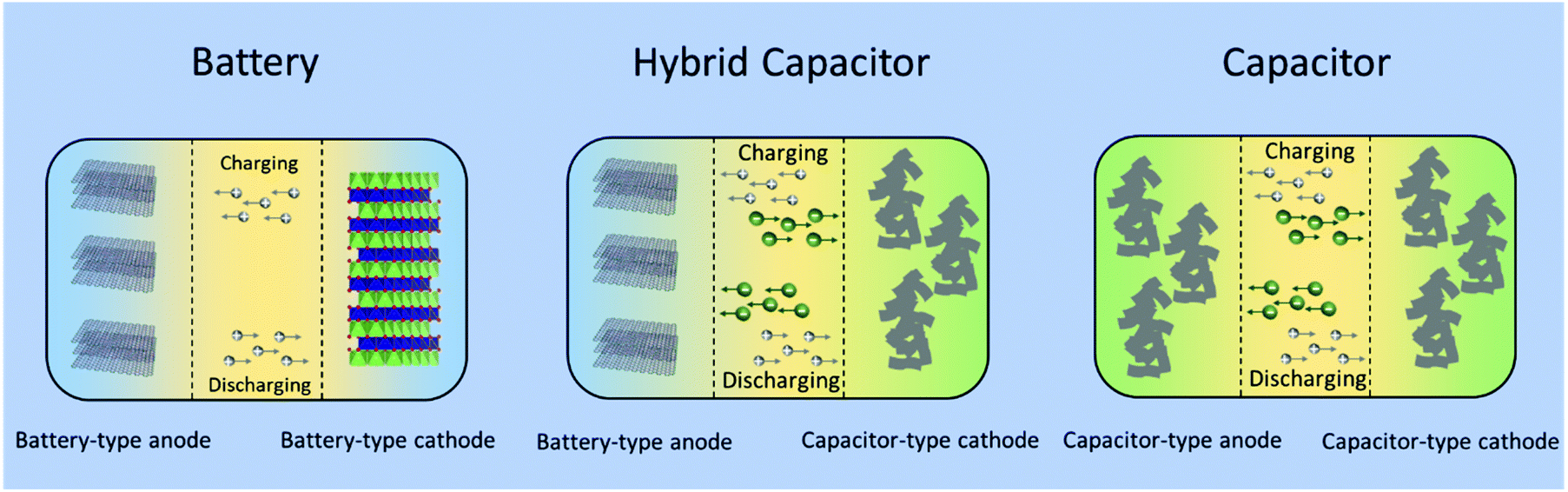 | ||
| Fig. 6 Schematic configurations for a typical battery (left), a typical non-aqueous hybrid capacitor (middle) and a typical capacitor (right). | ||
However, it is important to remember that the faradaic reactions are much more sluggish than the non-faradaic ones and that the charge storage capability of capacitor-type materials falls behind that of battery-type materials. Therefore, the main challenge in LICs/NICs research is to counteract the imbalance of kinetics and capacity between the faradaic anode and the non-faradaic capacitive cathode.60 In section 5, we will present several examples, how the advantages of batteries and EDLCs can efficiently be combined by developing suitable electrode materials.
4. Recent advancements in pseudocapacitive materials for high-power Li+/Na+ storage
4.1 Surface redox pseudocapacitive materials
Pseudocapacitive materials for high-power Li+/Na+ storage can be divided into the two families of surface redox and intercalation pseudocapacitive materials. For surface redox pseudocapacitive materials, electrochemical reactions are more likely to occur on or near the surface of the electrode materials. Thus, these reactions are not diffusion (into the particles) controlled, leading to a high power density. Moreover, surface redox pseudocapacitive materials can show intrinsic and extrinsic pseudocapacitance. As an example for intrinsic surface redox pseudocapacitance, RuO2 exhibits pseudocapacitive features for a wide range of particle sizes and morphologies.10 In 2007, Dunn et al. found that by engineering TiO2 (anatase) at the nanoscale, the contribution of pseudocapacitance increased with the reduction of the average size of the nanoparticles.42 They proved that the diffusion-controlled lithium intercalation processes could be replaced by surface reactions, which are non-diffusion controlled, with decreasing size of the nanoparticles. The study suggested that surface redox pseudocapacitance could be introduced through downsizing of the particles, known as extrinsic pseudocapacitance. Dou et al. tested the combination of rGO with MnO,61 which turned out to exhibit increasing surface redox pseudocapacitive effects with decreasing particle size of MnO. Embedding of the MnO nanoparticles in between two layers of rGO, the sandwich structure achieved an unprecedented rate capability (331.9 mA h g−1 at 10 mA cm−2, 379 mA h g−1 after 4000 cycles at 3.75 mA cm−2) with outstanding cycling stability. Other research results on surface redox pseudocapacitive materials harnessing the decreased particle size include ultrasmall MoC nanoparticles@nitrogen-doped porous carbon62 or 5 nm MnO nanocrystals-graphene composite.63In addition to particle size, morphological design plays another important role in improving the surface redox pseudocapacitive effects. Optimization of particle shape, in addition to composition and/or 3-dimensional architecture, can efficiently help to increase the surface area, thus providing more surface reaction sites. Sun et al. reported a facile and scalable strategy to fabricate hierarchical architectures, where TiO2 nanotube clusters were coated with a composite of ultrafine MoO2 nanoparticles embedded in a carbon matrix (TiO2@MoO2-C).64 When applied to Na-ion storage, the unique structural design led to high pseudocapacitance contribution with excellent cycling stability up to 10000 cycles even at a current density of 7 mA cm−2 and superior rate capacities of 110 and 76 mA h g−1 at current densities of 7 and 14 mA cm−2, respectively. An interesting study by Dunn et al. revealed that the surface redox pseudocapacitance greatly benefits from a mesoporous morphology and a specific crystal orientation. Ion intercalation pseudocapacitance was enhanced due to an ideal arrangement of the fast Li ion diffusion channels in the iso-oriented crystalline domains.56 Another class of porous materials are hollow nanostructures, which also showed enhanced redox pseudocapacitance. Lou et al. developed a template-directed strategy to synthesize NiS box-in-box hollow structures with double-shells.65 The hollow NiS built up by ultrathin nanosheets turned out to exhibit significantly improved specific capacitance compared to dense NiS. Other typical examples falling into this materials category include complex CoS hollow structures,66 NiCo2S4 ball-in-ball hollow spheres,67 and NixCo3−xS4 hollow nanoprisms,68 which all demonstrated enhanced pseudocapacitive properties compared with their counterparts with dense structures.
Xia and co-authors used surface engineering to successfully achieve ultrahigh rate capability via tunable surface redox pseudocapacitance.69 In their study, through modifying the surface of Fe2O3, they developed oxygen-deficient Fe2O3 quantum dots anchored on graphene nanosheets (V-F@G) (Fig. 7a). When using a redox active electrolyte such as Na2SO3, the surface oxygen vacancies enabled greatly enhanced chemical adsorption of SO32−. At the same time, the negatively charged surface of Fe2O3 with adsorbed SO32− attracts Na+ ions, facilitating both the formation of double-layer capacitance and surface redox reactions. The synergistic combination of redox reactions involving both the cation (Na+) and the anion (SO32−) on the Fe2O3 surface enabled rapid charge transport, i.e., high pseudocapacitance (Fig. 7b and c). Similarly, Yang et al. prepared oxygen-deficient Li3VO4−δ with an amorphous surface and also demonstrated the important role of surface engineering in enabling the fast surface reactions.70
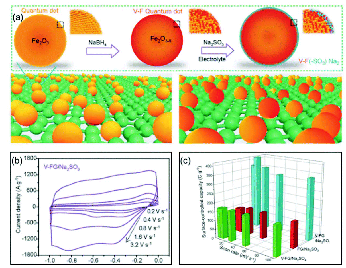 | ||
| Fig. 7 Example of a surface redox pseudocapacitive material: oxygen-deficient Fe2O3 quantum dots anchored on graphene nanosheets (V-F@G). (a) Schematic of the fabrication procedure of V-F@G and the adsorption of SO32− on the V-F@G surface. (b) CV curves of the V-F@G electrode measured in 1 M Na2SO3 electrolyte at high scan rates from 0.2 to 3.2 V s−1. (c) Surface-controlled capacity as a function of scan rate. Reproduced with permission from ref. 69. Copyright 2018, Wiley-VCH. | ||
4.2 Intercalation pseudocapacitive materials
Compared with surface redox pseudocapacitance, which generally needs to be enabled by complicated procedures of nanoscaling or nanostructuring, intercalation pseudocapacitance usually exists in bulk materials, if the ion pathways in the crystalline network are spacious enough to provide fast diffusion. As mentioned above, orthorhombic Nb2O5 (T-Nb2O5) with an open, layered structure is a typical intercalation pseudocapacitive material. Ganesh et al. carefully studied the origin of high-rate intercalation pseudocapacitance in this material.71 Based on complementary theoretical methods, the authors concluded that the intercalation pseudocapacitive behavior in Nb2O5 was due to the following reasons: (i) the presence of interconnected sheets with multiple adsorption sites of comparable energies; (ii) local charge-transfer at all adsorption sites; (iii) open channels that reduce the diffusion barrier for lithium to hop between these sites; (iv) the lack of 1st order phase transition upon intercalation/deintercalation. In addition to mechanistic studies, efforts were also made to further improve the electrochemical performance of T-Nb2O5. For example, Long et al. reported a simple synthesis method for free-standing orthorhombic Nb2O5 (T-Nb2O5)@graphene composite papers (Fig. 8a), which showed a superior pseudocapacitor performance (Fig. 8b–d).72 Using the composite paper, an organic electrolyte-based asymmetric supercapacitor was assembled, delivering a high energy density of 47 W h kg−1 and a power density of 18 kW kg−1. Yin and co-authors prepared three-dimensionally ordered macroporous T-Nb2O5 with mesoporous hierarchical structure, which turned out to offer highly efficient pseudocapacitive Li+ intercalation behavior.73 In another study, an in-plane assembled orthorhombic Nb2O5 nanorod film was prepared by Liu et al., which also showed high-rate Li+ intercalation.74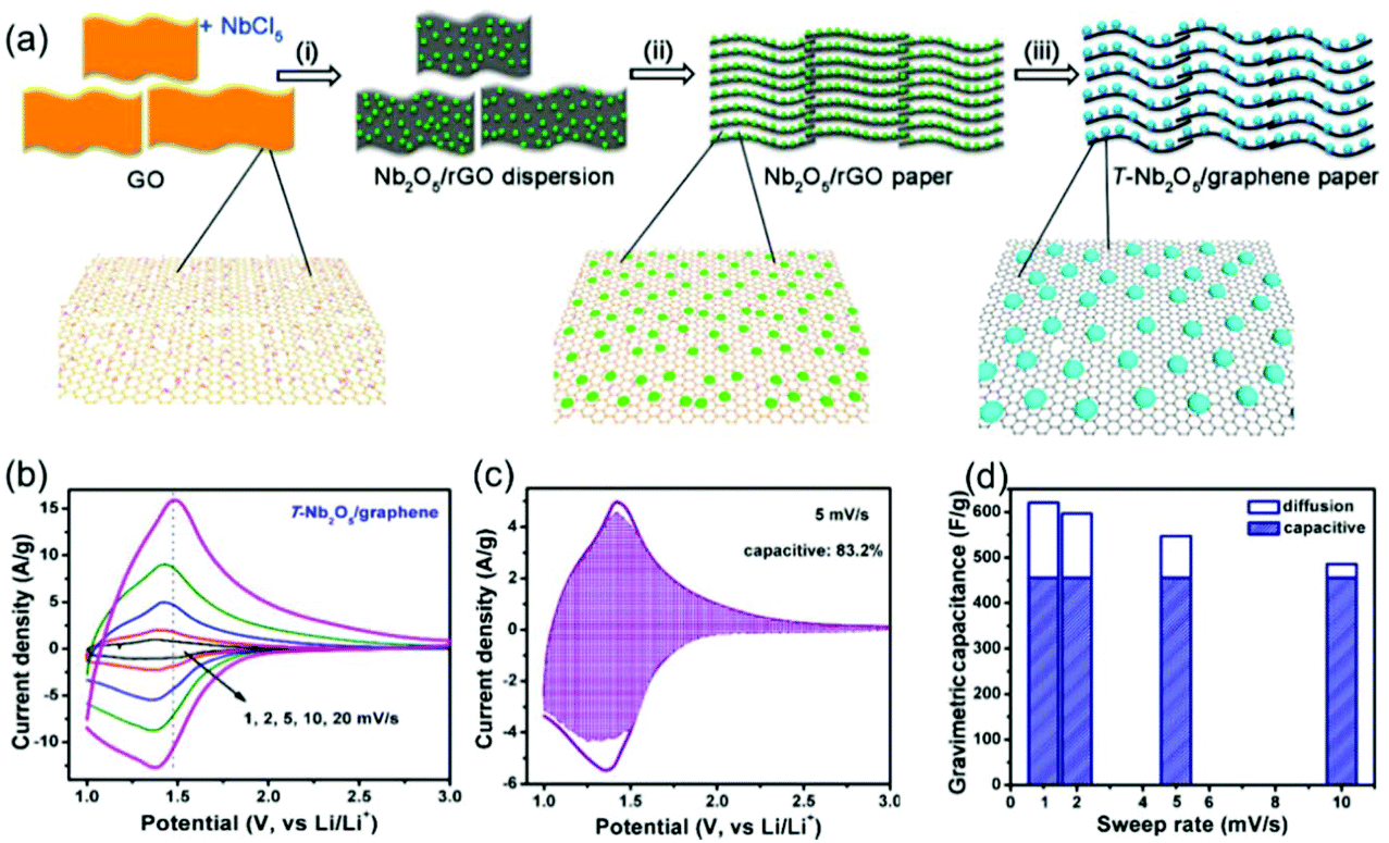 | ||
| Fig. 8 T-Nb2O5/graphene composite papers as an example of an intercalation pseudocapacitive materials. (a) Schematic of the fabrication process of the T-Nb2O5/graphene composite papers. (b) CV curves of the T-Nb2O5/graphene composite papers. (c) Total current (solid line) and capacitive current (shade regions) at 5 mV s−1 and (d) capacitive contribution at various scan rates for the T-Nb2O5/graphene composite papers. Reproduced with permission from ref. 72. Copyright 2015, American Chemical Society. | ||
Since the discovery of the intercalation pseudocapacitance in T-Nb2O5, a lot of efforts were devoted to exploring new materials with similar electrochemical behavior. In addition to T-Nb2O5, also spinel LiFeTiO4,52 MoO3−x with oxygen vacancies,75 and layered materials such as VOPO4 nanosheets76 and Ti2CTx MXene76 were proved to demonstrate intercalation pseudocapacitive behaviors. In the case of α-MoO3−x, Dunn et al. found that the reduced α-MoO3−x showed much higher rate capability and cycling stability than fully oxidized α-MoO3. The authors proposed three reasons for the enhancement in the electrochemical performance, which all positively affected the intercalation pseudocapacity. X-ray powder diffraction (XRD) and density functional theory (DFT) results revealed an expanded b-lattice cell parameter for the reduced α-MoO3−x relative to the oxidized α-MoO3, which led to a larger interlayer spacing that promoted faster charge storage kinetics. Ex situ XRD measurements pointed to an irreversible electrochemically induced phase transition in the oxidized α-MoO3 during Li+ insertion/extraction. In contrast, α-MoO3−x did not undergo a phase transformation following lithiation to 1.5 V, indicating better structural reversibility. Ex situ XPS measurements provided the information that α-MoO3−x experienced increased conversion of Mo6+ to Mo4+ compared with MoO3, which resulted in a capacity difference.
MXenes, discovered by Gogotsi, Barsoum and colleagues, have been developed as a novel family of 2D materials.77–80 Due to the large interlayer space, MXenes with intercalation pseudocapacitance are treated as promising candidates for high-power energy storage materials. Based on the pseudocapacitive behavior, Yamada et al. successfully applied MXenes in a high-power NIC. The prototype full cell consisting of a Na2Fe2(SO4)3 positive electrode and a MXene Ti2CTx negative electrode provided reversible capacities of 90 and 40 mA h g−1 at 1 and 5 mA cm−2, respectively (based on the weight of Ti2CTx).81 Regarding the underlying mechanism of the Na-ion intercalation pseudocapacitance, Yamada and colleagues found that the trapped Na+ after the first sodiation process behaves as a pillar and the penetrated solvent molecules swelled the interlayer space, both of which contributed to keep the interlayer distance constant during the sodiation/desodiation processes.82 Therefore, no substantial change in the interlayer distance was observed during electrochemical reactions, resulting in high cycling stability in addition to fast Na+ diffusion in the expanded interlayer space. Zhou et al.83 proved that a surface termination with –F and –OH in MXene blocked electrolyte ion transport and decreased energy storage capacity. Accordingly, Lin, Sun and co-authors demonstrated that after K+ intercalation and removal of terminal groups (OH−/F−), the intercalation pseudocapacitance was three times higher than that of the pristine MXene, which was reflected in a significant enhancement of about 211% of the gravimetric capacitance.53 In addition to carbide MXenes, also nitride MXenes, e.g., Ti2NTx MXene,84 have been proved to show pseudocapacitive charge storage mechanisms.
Recently, various layered metal vanadates, e.g., Ca0.24V2O5·0.83H2O,85 Mg0.34V2O5·0.84H2O,86 Zn3V2O7(OH)2·2H2O,87 or NaV3O8·1.5H2O88 were investigated as intercalation pseudocapacitive materials for high-power energy storage due to their crystal structure characterized by an open framework. In the case of Ca0.24V2O5·0.83H2O, Alshareef and co-authors proved that the high diffusion coefficient as a result of the large size of the cavity and the high electronic conductivity positively influenced the intercalation pseudocapacitive behavior of the material, resulting in a high rate capability and cycling stability.
Regarding practical applications of pseudocapacitive materials, the mass loading is a critical parameter. How to achieve high rate capability in thick electrodes has become an important question. Tolbert et al. reported a pseudocapacitive behavior in mesoporous MoS2 thin films, which was related to the ordered porosity and the iso-oriented crystal structure.55 To further explore the application of such pseudocapacitive materials in thick film electrodes, the authors used precycling steps to convert the 2H phase of MoS2 into the more conductive 1T phase, which was then processed into a carbon fiber-based highly conductive porous electrode. Synergistic combination of crystal structure engineering with a conductive carbon-based mesh electrode structure successfully preserved the good rate performance in the thicker electrodes.89
5. Recent advancements in non-aqueous LICs/NICs
Despite the attractive merits of non-aqueous hybrid capacitors mentioned above, the relatively low charge storage capability of the capacitive cathode and the kinetics mismatch between the anode and the cathode remain the main challenges.5.1. Cathode
Activated carbon (AC) is commonly selected as the cathode material in non-aqueous hybrid capacitor research due to its ultrahigh surface area and high electronic conductivity.60,90–93 However, the energy storage ability of an AC cathode can currently only achieve a capacity of ∼50 mA h g−1, which is insufficient compared with anode materials. In non-aqueous hybrid capacitors utilizing AC as the cathode, this problem is addressed by chosing the mass loading of the cathode two to four times higher than that of the anode. Therefore, to increase capacity and capacitance, the development of cathode materials with higher charge storage capacity represents a major task.Carbon sheets with 3D architectures showed great promise for high-performance capacitive cathodes for non-aqueous hybrid capacitors. Chen et al. reported a graphene-based three-dimensional porous carbon material (3DGraphene) with high surface area (≈3355 m2 g−1) as positive electrode material in a non-aqueous hybrid capacitor.94 Due to the extremely large amount of adsorption sites as well as the high electronic conductivity of this 3DGraphene, the material delivered a high specific capacitance ranging from 148 to 187 F g−1 at current densities of 0.096 to 9.55 mA cm−2. Metal–organic frameworks (MOFs) can also be utilized as a platform for the synthesis of porous carbon materials. Yan and Zhang et al. reported the synthesis of capacitor-like porous carbon polyhedra and a battery-like MoS2-ZIF composite using the same precursor of MOF (polyhedral ZIF-8).95 Due to the porous structure of the parent ZIF-8, the obtained porous carbon polyhedra showed a continuous 3D porous network with a high surface area and a well-controlled pore size, resulting in the typical capacitive behavior with a large specific capacitance. Despite the merits that such 3D frameworks of carbon possess, a simple synthesis methodology is important to bridge the gap between laboratory and industry. Yan et al. presented a promising approach for the large-scale preparation of highly porous carbon material through direct calcination of sodium citrate.96 This method works without the use of any additional carbon source, template, or catalyst. Through first-principle calculations, the authors verified that the large interlayer spacing and the curved particle shape facilitated the high rate ion storage.
N-Doping is an efficient way to enhance the charge storage capability of carbon materials, because the nitrogen atoms substituting carbon atoms in the graphite matrix are electron donors and promote n-type conductivity.97,98 Cai and Zhang et al. successfully prepared nitrogen-doped activated carbon through a one-step process.99 The obtained N-doped AC exhibited high surface areas of up to 2900 m2 g−1, resulting in a high specific capacity of 129 mA h g−1 at 1.6 mA cm−2. The authors found that the electrochemical performances of the N-doped AC materials were dependent on the N content. AC with 2.97 wt% N (NAC 400) showed better performance than the one with 3.98 wt% N (NAC 600). The authors attributed this observation to the larger concentration of oxidized pyridinic N found in NAC-600 and the relatively lower surface area of NAC-600. The work by Xia, Yu and co-authors demonstrated that the dual doping of B and N in carbon nanofibers exhibited greatly improved electrochemical performance when applied as cathode for LICs (Fig. 9).100 They proved that the B, N dual doping significantly enhanced the surface area, enlarged the carbon interlayer distance, increased the number of the active sites, and improved the electrode kinetics of the carbon nanofibers. The B,N dual doped carbon nanofibers could not only be used as the cathode, but also exhibited high performance as the anode. A symmetric LIC employing the carbon nanofibers as both binder-free cathode and anode achieved a high energy density of 104 W h kg−1 at 22500 W kg−1.
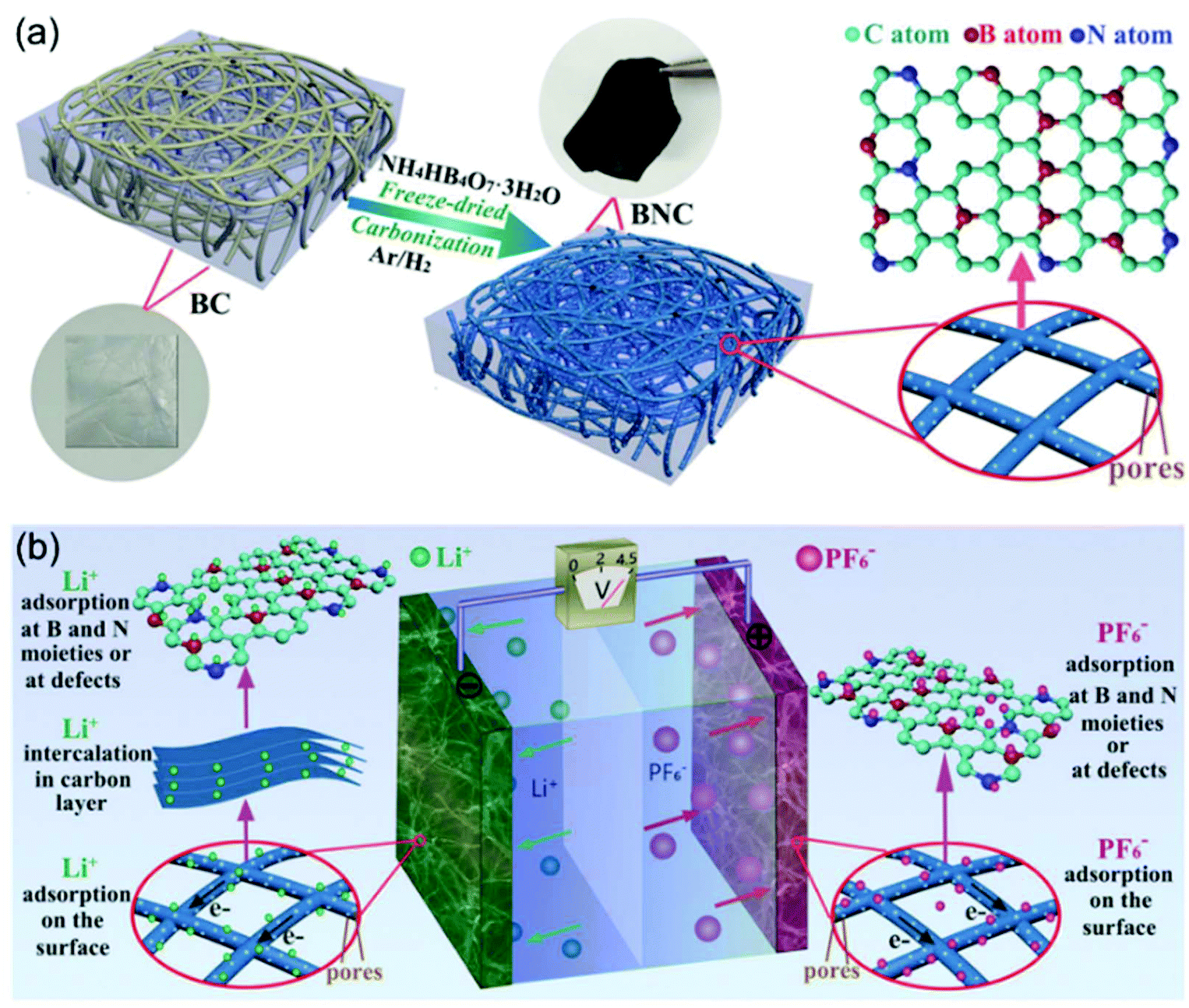 | ||
| Fig. 9 Example of an advanced non-aqueous hybrid capacitor: A LIC using B and N dual-doped carbon nanofibers as both the cathode and the anode. (a) Schematic of the fabrication process of BNC. (b) Schematic of the charge-storage mechanisms of BNC//BNC LIC. Reproduced with permission from ref. 100. Copyright 2017, Wiley-VCH. | ||
Highly porous carbon materials derived from natural resources are regarded as an eco-friendly way to prepare high-performance cathodes for non-aqueous hybrid capacitors. For instance, Lee and co-workers successfully prepared high-surface-area activated carbon derived from cinnamon sticks. The bio-inspired AC provided a high cycling stability and an average discharge capacity of 60 mA h g−1 at a current rate of 400 mA g−1.101 Mitlin et al. reported a porous carbon material with sheet-like morphology derived from peanut shells. Based on a tailored synthesis strategy combining a hydrothermal and a chemical activation process, a carbon material with macroscopically open sheet-like morphology was prepared, delivering an extremely high capacity of 73 mA h g−1 at 10.24 mA cm−2.102
It has to be noticed that carbon materials with EDLC mechanisms usually have high surface areas, which inevitably result in relatively low volumetric energy densities. In response to this issue, efforts have been made to find intercalation pseudocapacitive cathode materials. For instance, nanoporous LiMn2O4 with pseudocapacitive characteristics has been proved to show great promise as a fast-charging cathode material.103
5.2. Anode
The main challenge on the anode side for the fabrication of high-performance non-aqueous hybrid capacitors is to find a material that is able to match the fast kinetics of the cathode. A lot of pseudocapacitive materials have been investigated as the anode in both LICs and NICs. In a recent study, we reported a general method for the synthesis of structurally disordered nanoparticles@reduced graphene oxide (rGO) composite aerogels, which were directly used as high-power pseudocapacitive anodes for LICs.104 To clarify the effect of the degree of disorder, control samples of crystalline nanoparticles with similar particle size were prepared. A schematic of the preparation route to crystalline and structurally disordered composite aerogels is shown in Fig. 10. Cyclic voltammetry analysis and density functional theory calculations indicated that the structurally disordered samples exhibited a smaller volume expansion during Li+ insertion and larger pseudocapacitive effects than the crystalline reference samples. As a result, structurally disordered samples showed much better Li-ion storage performances. Combined with commercial activated carbon as the cathode, the structurally disordered CoxFeyOz@rGO delivered higher energy densities than crystalline CoFe2O4@rGO when tested at the same power densities. These results indicate that nanomaterials with a low crystallinity and a large number of defects might be interesting for high-power anodes for LICs.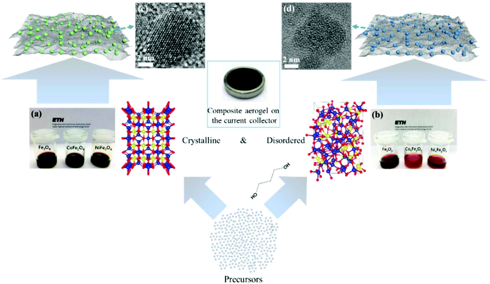 | ||
| Fig. 10 Schematic of the preparation of crystalline and structurally disordered composite aerogels. Reproduced with permission from ref. 104. Copyright 2018, American Chemical Society. | ||
For the applications in NICs, Kim et al. introduced SnS2@graphene-CNT aerogels with pseudocapacitive behavior, which turned out to result in an energy density of 26.9 W h kg−1 at power densities of 6053 W kg−1, respectively.105 We also reported a reduced graphene oxide-Zn0.25V2O5·nH2O nanobelt composite (G-ZVO) as a pseudocapacitive anode for NICs.106 Due to the large interplanar spacings in the crystal structure of Zn0.25V2O5·nH2O and the high electronic conductivity of the composite, the active material was characterized by high pseudocapacitive contributions of up to 85% at 1 mV−1 (Fig. 11a) and high rate capability. Pairing it with a hard salt-templated, ordered mesoporous carbon as a high-performance capacitive cathode (OM-HSTC) resulted in a Na-ion hybrid capacitor (Fig. 11b), which delivered a good cycling performance (31.7 W h kg−1 (i.e., 87%) retained after 2000 cycles at 1.5 mA cm−2, Fig. 11c). The study supports the idea that layer-structured materials with large interlayer spacings might be suitable for NICs involving intercalation mechanisms. To get a general idea of the achievements in the field of non-aqueous hybrid capacitors, some recently published results on LICs and NICs are summarized in Table 2.
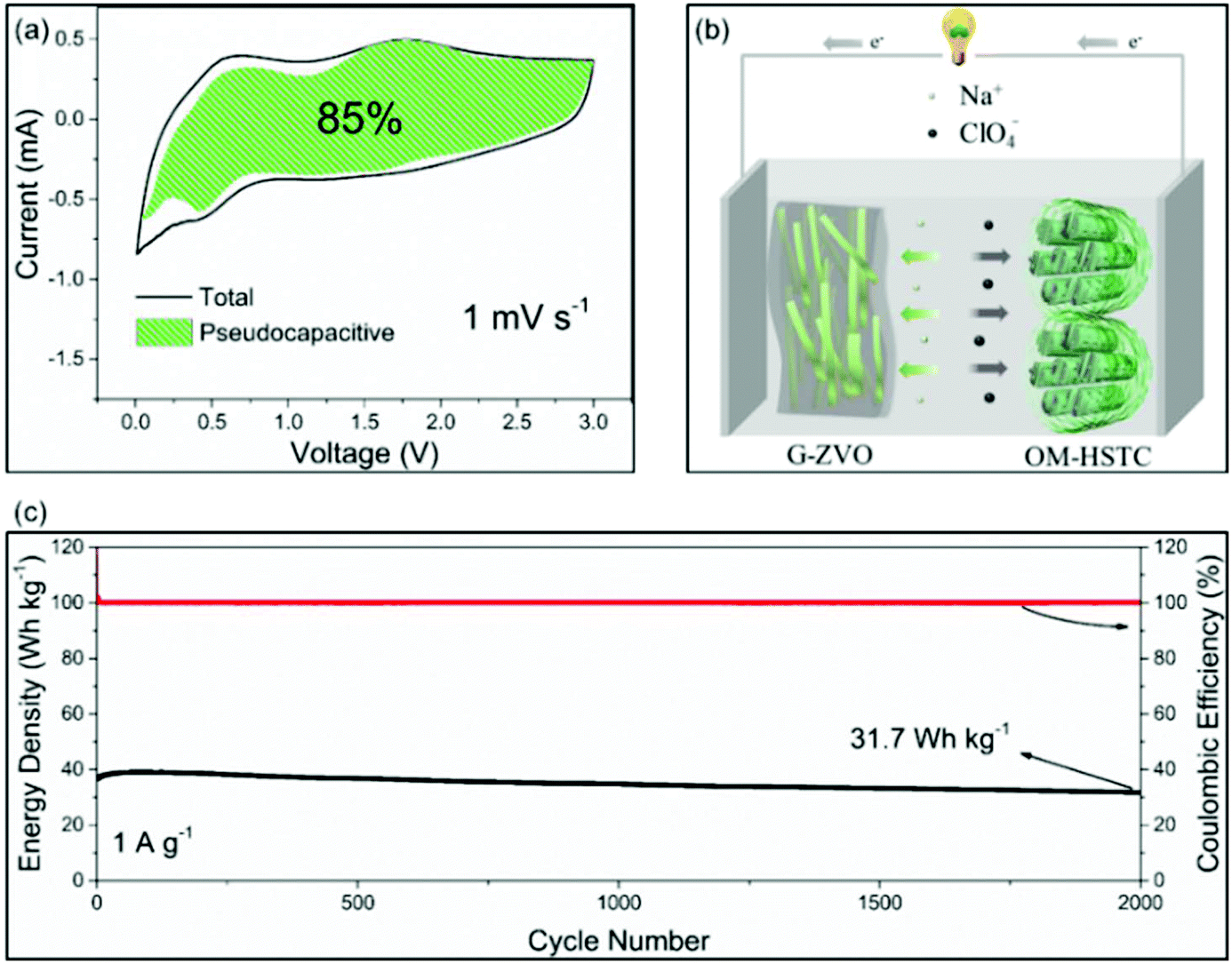 | ||
| Fig. 11 (a) Voltammetric response of G-ZVO with separation between total current and pseudocapacitive current at a scan rate of 1 mV s−1. (b) Schematic of the G-ZVO||OM-HSTC hybrid device. (c) Long-term cycling stability performance of the G@ZVO||OM-HSTC hybrid device at 1.5 mA cm−2. Reproduced with permission from ref. 106. Copyright 2018, Wiley-VCH. | ||
| Type of device | Anode//cathode [reference] | Potential range (V) | Energy density (W h kg−1) | Power density (W kg−1) | Cycling life/capacity retention | Publication year |
|---|---|---|---|---|---|---|
| LIC | 3D inverse opal-structured FeS-QDs@N-doped carbon//AC107 | 0.5–3.4 | 72.2 | 9280 | 5000 cycles/91% | 2019 |
| LIC | Co3ZnC@N-doped carbon//microporous carbon108 | 1.0–4.5 | 15.2 | 10300 |
1000 cycles/80% | 2018 |
| LIC | P-WO3−x@N-doped carbon//AC109 | 0.01–4.3 | 113.84 | 11946 |
6000 cycles/90.7% | 2018 |
| LIC | Li3VO4@N-doped carbon//AC110 | 1.0–4.0 | 24.4 | 11020 |
1500/— | 2017 |
| LIC | MoS2@RGO//AC111 | 0–4.0 | 45.3 | 40000 |
10000 cycles/∼80% |
2017 |
| LIC | B and N dual-doped carbon nanofibers (BNC)//BNC100 | 0.02–4.5 | 104 | 22500 |
5000 cycles/81% | 2017 |
| LIC | Si@C//nitrogen-doped AC99 | 2.0–4.5 | 141 | 30127 |
8000 cycles/76.3% | 2016 |
| LIC | Si/C//egg white-derived AC112 | 2.0–4.5 | 147 | 29893 |
15000 cycles/79.2% |
2016 |
| LIC | TiC//porous nitrogen-doped carbon113 | 0–4.5 | 23.4 | 67500 |
5000 cycles/∼82% | 2016 |
| LIC | 3D VN-RGO//porous carbon nanorods114 | 0–4.0 | 64 | 10000 |
1000 cycles/83% | 2015 |
| LIC | MnO@graphene//porous N-doped carbon63 | 1.0–4.0 | 83.25 | 25000 |
3000 cycles/76% | 2015 |
| LIC | Anatase TiO2@rGO//AC115 | 1.0–3.0 | 42 | 8000 | 10000 cycles/80% |
2013 |
| NIC | MoSe2@graphene//AC116 | 0.5–3.0 | 43 | 6688 | 5000 cycles/81% | 2018 |
| NIC | Gr-Nb2O5//AC117 | 1.0–4.3 | 80.1 | 5330 | — | 2018 |
| NIC | 3D framework carbon (3DF)//3DFC-derived nanoporous carbon96 | 0–4.0 | 67 | 20000 |
1000 cycles/95.3% | 2018 |
| NIC | TiO2@C//MOFs-derived 3D nanoporous carbon118 | 1.0–4.0 | 61.8 | 25000 |
10000 cycles/90% |
2018 |
| NIC | TiO2@CNT@C//biomass-derived carbon119 | 1.0–4.0 | 37.9 | 12400 |
5000 cycles/85.3% | 2017 |
| NIC | NaTi2(PO4)3@graphene//2D graphene nanosheets120 | 0–3.0 | 80 | 8000 | 75000 cycles/90% |
2017 |
| NIC | Peanut shell nanosheet carbon//low surface area peanut shell ordered carbon102 | 1.5–3.5 | 50 | 16500 |
10000 cycles/72% |
2015 |
6. Conclusions and outlook
The goal of this minireview was, on the one hand, to introduce the fundamentals of pseudocapacitance and non-aqueous hybrid capacitors for the non-expert readers and, on the other hand, to provide a general overview of the recent developments in pseudocapacitive materials and Li-ion/Na-ion hybrid capacitors for the broad scientific community interested in novel energy storage devices. Pseudocapacitive materials and non-aqueous hybrid capacitors have shown that they hold great potential to contribute towards fast-charging technologies. However, we are far away from exploiting their full potential. For future advancements, several critical issues have to be considered.Compared to the progress made in high-rate pseudocapacitive anode materials, the exploration of pseudocapacitive cathode materials with comparable performance is clearly lagging behind. However, from the perspective of the full-cell level, this problem has to be solved. The concept of non-aqueous hybrid capacitors was put forward to push the limit of energy density of electrical double layer capacitors. On the cathode side, the electrostatic double layer charge storage capability of activated carbon materials is dependent on the surface area. Unfortunately, high surface area inevitably results in low volumetric energy densities. To tackle this aspect, the development of advanced intercalation pseudocapacitive cathode materials might be a promising strategy.
In addition, most studies on pseudocapacitive materials are based on very thin electrodes and extremely small particle sizes. Despite that these studies provide instructive understanding of the basic science, they are practically not relevant.121 The issue here is that increased electrode thickness will result in serious polarization, hence affecting the ion storage kinetics. Furthermore, with very small particle sizes, unexpectedly poor efficiency and high self-discharge rate will arise. Crystal structure engineering and creation of interconnected porous architectures with continuous electronic and ionic conductive pathways might be possible solutions for these problems.
To bring pseudocapacitive materials closer to the application, we hereby suggest a few guidelines for electrode preparation: The electrodes should be with areal loadings of at least 2–4 mg cm−2; maximum porosity of 35% is acceptable; the content of inactive components like conductive carbon black and binder should not exceed 8%. Future studies taking these considerations into account will be especially beneficial for the practical application of pseudocapacitive materials.
The research area of pseudocapacitive materials and non-aqueous hybrid capacitors is quickly moving forward and it is not always straightforward to establish clear and universal definitions. To help to identify pseudocapacitive materials and to provide suggestions for the study of non-aqueous hybrid capacitors, we propose three key points: (i) The electrode preparation should be based on the considerations mentioned before; (ii) to be qualified as pseudocapacitive, a material should have a capacitive contribution of more than 70% at 1 mV s−1 based on CV analysis, intense and separated oxidative and reductive peaks should not be observed in CV curves, dQ/dV derived from charging–discharging-curves should be approaching a constant value and phase transformation measurements should be carried out and materials with phase transitions within the operating voltage window should not be called intercalation pseudocapacitive materials; and (iii) performances of non-aqueous hybrid capacitors should be tested at power densities >5000 W kg−1.
Conflicts of interest
There are no conflicts to declare.Acknowledgements
The authors acknowledge ETH Zurich and China Scholarship Council for financial support.Notes and references
- J. W. Choi and D. Aurbach, Nat. Rev. Mater., 2016, 1, 16013–16028 CrossRef CAS.
- S. W. Kim, D. H. Seo, X. Ma, G. Ceder and K. Kang, Adv. Energy Mater., 2012, 2, 710–721 CrossRef CAS.
- M. Armand and J. M. Tarascon, Nature, 2008, 451, 652–657 CrossRef CAS PubMed.
- D. Lin, Y. Liu and Y. Cui, Nat. Nanotechnol., 2017, 12, 194–206 CrossRef CAS PubMed.
- X.-B. Cheng, R. Zhang, C.-Z. Zhao and Q. Zhang, Chem. Rev., 2017, 117, 10403–10473 CrossRef CAS PubMed.
- X. Ji, K. T. Lee and L. F. Nazar, Nat. Mater., 2009, 8, 500–506 CrossRef CAS PubMed.
- P. G. Bruce, S. A. Freunberger, L. J. Hardwick and J.-M. Tarascon, Nat. Mater., 2012, 11, 19–29 CrossRef CAS PubMed.
- Z. Peng, S. A. Freunberger, Y. Chen and P. G. Bruce, Science, 2012, 337, 563–566 CrossRef CAS PubMed.
- Y. Liu, Y. Zhu and Y. Cui, Nat. Energy, 2019, 4, 540–550 CrossRef.
- V. Augustyn, P. Simon and B. Dunn, Energy Environ. Sci., 2014, 7, 1597–1614 RSC.
- K. Naoi, W. Naoi, S. Aoyagi, J.-I. Miyamoto and T. Kamino, Acc. Chem. Res., 2012, 46, 1075–1083 CrossRef PubMed.
- K. Naoi, S. Ishimoto, J.-I. Miyamoto and W. Naoi, Energy Environ. Sci., 2012, 5, 9363–9373 RSC.
- T. Brousse, D. Bélanger and J. W. Long, J. Electrochem. Soc., 2015, 162, A5185–A5189 CrossRef CAS.
- K. Naoi and Y. Nagano, in Supercapacitors, 2013, Wiley-VCH Verlag GmbH & Co. KGaA, pp. 239–256 Search PubMed.
- K. Naoi, Fuel Cells, 2010, 10, 825–833 CrossRef CAS.
- N. Yabuuchi, K. Kubota, M. Dahbi and S. Komaba, Chem. Rev., 2014, 114, 11636–11682 CrossRef CAS PubMed.
- L. P. Wang, L. Yu, X. Wang, M. Srinivasan and Z. J. Xu, J. Mater. Chem. A, 2015, 3, 9353–9378 RSC.
- M. D. Slater, D. Kim, E. Lee and C. S. Johnson, Adv. Funct. Mater., 2013, 23, 947–958 CrossRef CAS.
- S. Y. Hong, Y. Kim, Y. Park, A. Choi, N.-S. Choi and K. T. Lee, Energy Environ. Sci., 2013, 6, 2067–2081 RSC.
- J. Liu, J. Wang, C. Xu, H. Jiang, C. Li, L. Zhang, J. Lin and Z. X. Shen, Adv. Sci., 2018, 5, 1700322 CrossRef PubMed.
- J. R. Miller and P. Simon, Science, 2008, 321, 651–652 CrossRef CAS PubMed.
- P. J. Hall, M. Mirzaeian, S. I. Fletcher, F. B. Sillars, A. J. Rennie, G. O. Shitta-Bey, G. Wilson, A. Cruden and R. Carter, Energy Environ. Sci., 2010, 3, 1238–1251 RSC.
- B. E. Conway, J. Electrochem. Soc., 1991, 138, 1539–1548 CrossRef CAS.
- B. Conway, V. Birss and J. Wojtowicz, J. Power Sources, 1997, 66, 1–14 CrossRef CAS.
- Y. Gogotsi and R. M. Penner, ACS Nano, 2018, 12, 2081–2083 CrossRef CAS PubMed.
- B. Conway, Electrochim. Acta, 1993, 38, 1249–1258 CrossRef CAS.
- S. Trasatti and G. Buzzanca, J. Electroanal. Chem. Interfacial Electrochem., 1971, 29, A1–A5 CrossRef.
- J. Zheng, P. Cygan and T. Jow, J. Electrochem. Soc., 1995, 142, 2699–2703 CrossRef CAS.
- J. W. Long, K. E. Swider, C. I. Merzbacher and D. R. Rolison, Langmuir, 1999, 15, 780–785 CrossRef CAS.
- V. Augustyn, J. Come, M. A. Lowe, J. W. Kim, P.-L. Taberna, S. H. Tolbert, H. D. Abruña, P. Simon and B. Dunn, Nat. Mater., 2013, 12, 518–522 CrossRef CAS PubMed.
- J. W. Kim, V. Augustyn and B. Dunn, Adv. Energy Mater., 2012, 2, 141–148 CrossRef CAS.
- C.-P. Liu, F. Zhou and V. Ozolins, in APS Meeting Abstracts, 2012 Search PubMed.
- A. Djire, P. Pande, A. Deb, J. B. Siegel, O. T. Ajenifujah, L. He, A. E. Sleightholme, P. G. Rasmussen and L. T. Thompson, Nano Energy, 2019, 60, 72–81 CrossRef CAS.
- A. Djire, J. B. Siegel, O. Ajenifujah, L. He and L. T. Thompson, Nano Energy, 2018, 51, 122–127 CrossRef CAS.
- A. Djire, O. Ajenifujah and L. T. Thompson, Batteries Supercaps, 2018, 1, 171–175 CrossRef CAS.
- R. E. Ruther, C.-N. Sun, A. Holliday, S. Cheng, F. M. Delnick, T. A. Zawodzinski and J. Nanda, J. Electrochem. Soc., 2017, 164, A277–A283 CrossRef CAS.
- N. Jabeen, Q. Xia, S. V. Savilov, S. M. Aldoshin, Y. Yu and H. Xia, ACS Appl. Mater. Interfaces, 2016, 8, 33732–33740 CrossRef CAS PubMed.
- A. Yamada, S.-C. Chung and K. Hinokuma, J. Electrochem. Soc., 2001, 148, A224–A229 CrossRef CAS.
- G. Z. Chen, Prog. Nat. Sci., 2013, 23, 245–255 CrossRef.
- J. Come, P.-L. Taberna, S. Hamelet, C. Masquelier and P. Simon, J. Electrochem. Soc., 2011, 158, A1090–A1093 CrossRef CAS.
- H. Y. Lee and J. B. Goodenough, J. Solid State Chem., 1999, 144, 220–223 CrossRef CAS.
- J. Wang, J. Polleux, J. Lim and B. Dunn, J. Phys. Chem. C, 2007, 111, 14925–14931 CrossRef CAS.
- P. Zanello, Inorganic Electrochemistry: Theory, Practice and Application, Royal Society of Chemistry, 2011 Search PubMed.
- S. Ardizzone, G. Fregonara and S. Trasatti, Electrochim. Acta, 1990, 35, 263–267 CrossRef CAS.
- Z. Le, F. Liu, P. Nie, X. Li, X. Liu, Z. Bian, G. Chen, H. B. Wu and Y. Lu, ACS Nano, 2017, 11, 2952–2960 CrossRef CAS PubMed.
- C. Costentin, T. R. Porter and J.-M. SavéAnt, ACS Appl. Mater. Interfaces, 2017, 9, 8649–8658 CrossRef CAS PubMed.
- B. E. Conway, Electrochemical Supercapacitors: Scientific Fundamentals and Technological Applications, Kluwer-Academic, 1999 Search PubMed.
- J. B. Cook, T. C. Lin, H.-S. Kim, A. Siordia, B. S. Dunn and S. H. Tolbert, ACS Nano, 2019, 13, 1223–1231 CAS.
- H.-S. Kim, J. B. Cook, S. H. Tolbert and B. Dunn, J. Electrochem. Soc., 2015, 162, A5083–A5090 CrossRef CAS.
- G. A. Muller, J. B. Cook, H.-S. Kim, S. H. Tolbert and B. Dunn, Nano Lett., 2015, 15, 1911–1917 CrossRef CAS PubMed.
- P. Simon, Y. Gogotsi and B. Dunn, Science, 2014, 343, 1210–1211 CrossRef CAS PubMed.
- R. Chen, M. Knapp, M. Yavuz, S. Ren, R. Witte, R. Heinzmann, H. Hahn, H. Ehrenberg and S. Indris, Phys. Chem. Chem. Phys., 2015, 17, 1482–1488 RSC.
- J. Li, X. Yuan, C. Lin, Y. Yang, L. Xu, X. Du, J. Xie, J. Lin and J. Sun, Adv. Energy Mater., 2017, 7, 1602725 CrossRef.
- M. Okubo, E. Hosono, J. Kim, M. Enomoto, N. Kojima, T. Kudo, H. Zhou and I. Honma, J. Am. Chem. Soc., 2007, 129, 7444–7452 CrossRef CAS PubMed.
- J. B. Cook, H. S. Kim, Y. Yan, J. S. Ko, S. Robbennolt, B. Dunn and S. H. Tolbert, Adv. Energy Mater., 2016, 6, 1501937 CrossRef.
- T. Brezesinski, J. Wang, S. H. Tolbert and B. Dunn, Nat. Mater., 2010, 9, 146–151 CrossRef CAS PubMed.
- Q. Wang, Z. Wen and J. Li, Adv. Funct. Mater., 2006, 16, 2141–2146 CrossRef CAS.
- H. Li, L. Peng, Y. Zhu, X. Zhang and G. Yu, Nano Lett., 2016, 16, 5938–5943 CrossRef CAS PubMed.
- D. P. Dubal, O. Ayyad, V. Ruiz and P. Gomez-Romero, Chem. Soc. Rev., 2015, 44, 1777–1790 RSC.
- E. Lim, C. Jo, M. S. Kim, M. H. Kim, J. Chun, H. Kim, J. Park, K. C. Roh, K. Kang and S. Yoon, Adv. Funct. Mater., 2016, 26, 3711–3719 CrossRef CAS.
- T. Yuan, Y. Jiang, W. Sun, B. Xiang, Y. Li, M. Yan, B. Xu and S. Dou, Adv. Funct. Mater., 2016, 26, 2198–2206 CrossRef CAS.
- X. Chen, L.-P. Lv, W. Sun, Y. Hu, X. Tao and Y. Wang, J. Mater. Chem. A, 2018, 6, 13705–13716 RSC.
- M. Yang, Y. Zhong, J. Ren, X. Zhou, J. Wei and Z. Zhou, Adv. Energy Mater., 2015, 5, 1500550 CrossRef.
- C. Zhao, C. Yu, M. Zhang, H. Huang, S. Li, X. Han, Z. Liu, J. Yang, W. Xiao, J. Liang, X. Sun and J. Qiu, Adv. Energy Mater., 2017, 7, 1602880 CrossRef.
- X.-Y. Yu, L. Yu, L. Shen, X. Song, H. Chen and X. W. Lou, Adv. Funct. Mater., 2014, 24, 7440–7446 CrossRef CAS.
- H. Hu, B. Y. Guan and X. W. D. Lou, Chem, 2016, 1, 102–113 CAS.
- L. Shen, L. Yu, H. B. Wu, X.-Y. Yu, X. Zhang and X. W. Lou, Nat. Commun., 2015, 6, 6694 CrossRef CAS PubMed.
- L. Yu, L. Zhang, H. B. Wu and X. W. Lou, Angew. Chem., Int. Ed., 2014, 53, 3711–3714 CrossRef CAS PubMed.
- T. Zhai, S. Sun, X. Liu, C. Liang, G. Wang and H. Xia, Adv. Mater., 2018, 30, 1706640 CrossRef PubMed.
- L. Chen, X. Jiang, N. Wang, J. Yue, Y. Qian and J. Yang, Adv. Sci., 2015, 2, 1500090 CrossRef PubMed.
- A. A. Lubimtsev, P. R. C. Kent, B. G. Sumpter and P. Ganesh, J. Mater. Chem. A, 2013, 1, 14951–14956 RSC.
- L. Kong, C. Zhang, J. Wang, W. Qiao, L. Ling and D. Long, ACS Nano, 2015, 9, 11200–11208 CrossRef CAS PubMed.
- S. Lou, X. Cheng, L. Wang, J. Gao, Q. Li, Y. Ma, Y. Gao, P. Zuo, C. Du and G. Yin, J. Power Sources, 2017, 361, 80–86 CrossRef CAS.
- B. Deng, T. Lei, W. Zhu, L. Xiao and J. Liu, Adv. Funct. Mater., 2018, 28, 1704330 CrossRef.
- H.-S. Kim, J. B. Cook, H. Lin, J. S. Ko, S. H. Tolbert, V. Ozolins and B. Dunn, Nat. Mater., 2017, 16, 454–460 CrossRef CAS PubMed.
- Y. Zhu, L. Peng, D. Chen and G. Yu, Nano Lett., 2015, 16, 742–747 CrossRef PubMed.
- M. Naguib, M. Kurtoglu, V. Presser, J. Lu, J. Niu, M. Heon, L. Hultman, Y. Gogotsi and M. W. Barsoum, Adv. Mater., 2011, 23, 4248–4253 CrossRef CAS PubMed.
- M. Naguib, O. Mashtalir, J. Carle, V. Presser, J. Lu, L. Hultman, Y. Gogotsi and M. W. Barsoum, ACS Nano, 2012, 6, 1322–1331 CrossRef CAS PubMed.
- O. Mashtalir, M. Naguib, V. N. Mochalin, Y. Dall'agnese, M. Heon, M. W. Barsoum and Y. Gogotsi, Nat. Commun., 2013, 4, 1716 CrossRef PubMed.
- M. R. Lukatskaya, O. Mashtalir, C. E. Ren, Y. Dall'agnese, P. Rozier, P. L. Taberna, M. Naguib, P. Simon, M. W. Barsoum and Y. Gogotsi, Science, 2013, 341, 1502–1505 CrossRef CAS PubMed.
- X. Wang, S. Kajiyama, H. Iinuma, E. Hosono, S. Oro, I. Moriguchi, M. Okubo and A. Yamada, Nat. Commun., 2015, 6, 6544 CrossRef CAS PubMed.
- S. Kajiyama, L. Szabova, K. Sodeyama, H. Iinuma, R. Morita, K. Gotoh, Y. Tateyama, M. Okubo and A. Yamada, ACS Nano, 2016, 10, 3334–3341 CrossRef CAS PubMed.
- Q. Tang, Z. Zhou and P. Shen, J. Am. Chem. Soc., 2012, 134, 16909–16916 CrossRef CAS PubMed.
- A. Djire, A. Bos, J. Liu, H. Zhang, E. M. Miller and N. R. Neale, ACS Appl. Nano Mater., 2019, 2, 2785–2795 CrossRef CAS.
- C. Xia, J. Guo, P. Li, X. Zhang and H. N. Alshareef, Angew. Chem., Int. Ed., 2018, 57, 3943–3948 CrossRef CAS PubMed.
- F. Ming, H. Liang, Y. Lei, S. Kandambeth, M. Eddaoudi and H. N. Alshareef, ACS Energy Lett., 2018, 3, 2602–2609 CrossRef CAS.
- C. Xia, J. Guo, Y. Lei, H. Liang, C. Zhao and H. N. Alshareef, Adv. Mater., 2018, 30, 1705580 CrossRef PubMed.
- F. Wan, L. Zhang, X. Dai, X. Wang, Z. Niu and J. Chen, Nat. Commun., 2018, 9, 1656 CrossRef PubMed.
- J. B. Cook, H. S. Kim, T. C. Lin, C. H. Lai, B. Dunn and S. H. Tolbert, Adv. Energy Mater., 2017, 7, 1601283 CrossRef.
- E. Lim, C. Jo, H. Kim, M.-H. Kim, Y. Mun, J. Chun, Y. Ye, J. Hwang, K.-S. Ha and K. C. Roh, ACS Nano, 2015, 9, 7497–7505 CrossRef CAS PubMed.
- H. Wang, C. Zhu, D. Chao, Q. Yan and H. J. Fan, Adv. Mater., 2017, 29, 1702093 CrossRef PubMed.
- Y. Ma, H. Chang, M. Zhang and Y. Chen, Adv. Mater., 2015, 27, 5296–5308 CrossRef CAS PubMed.
- J. Luo, W. Zhang, H. Yuan, C. Jin, L. Zhang, H. Huang, C. Liang, Y. Xia, J. Zhang and Y. Gan, ACS Nano, 2017, 11, 2459–2469 CrossRef CAS PubMed.
- F. Zhang, T. Zhang, X. Yang, L. Zhang, K. Leng, Y. Huang and Y. Chen, Energy Environ. Sci., 2013, 6, 1623–1632 RSC.
- R. Wang, D. Jin, Y. Zhang, S. Wang, J. Lang, X. Yan and L. Zhang, J. Mater. Chem. A, 2017, 5, 292–302 RSC.
- B. Yang, J. Chen, S. Lei, R. Guo, H. Li, S. Shi and X. Yan, Adv. Energy Mater., 2018, 8, 1702409 CrossRef.
- Z. R. Ismagilov, A. E. Shalagina, O. Y. Podyacheva, A. V. Ischenko, L. S. Kibis, A. I. Boronin, Y. A. Chesalov, D. I. Kochubey, A. I. Romanenko and O. B. Anikeeva, Carbon, 2009, 47, 1922–1929 CrossRef CAS.
- M. Terrones, P. Ajayan, F. Banhart, X. Blase, D. Carroll, J.-C. Charlier, R. Czerw, B. Foley, N. Grobert and R. Kamalakaran, Appl. Phys. A, 2002, 74, 355–361 CrossRef CAS.
- B. Li, F. Dai, Q. Xiao, L. Yang, J. Shen, C. Zhang and M. Cai, Energy Environ. Sci., 2016, 9, 102–106 RSC.
- Q. Xia, H. Yang, M. Wang, M. Yang, Q. Guo, L. Wan, H. Xia and Y. Yu, Adv. Energy Mater., 2017, 7, 1701336 CrossRef.
- R. Thangavel, K. Kaliyappan, K. Kang, X. Sun and Y. S. Lee, Adv. Energy Mater., 2016, 6, 1502199 CrossRef.
- J. Ding, H. Wang, Z. Li, K. Cui, D. Karpuzov, X. Tan, A. Kohandehghan and D. Mitlin, Energy Environ. Sci., 2015, 8, 941–955 RSC.
- B. K. Lesel, J. B. Cook, Y. Yan, T. C. Lin and S. H. Tolbert, ACS Energy Lett., 2017, 2, 2293–2298 CrossRef CAS.
- H. Huang, X. Wang, E. Tervoort, G. Zeng, T. Liu, X. Chen, A. Sologubenko and M. Niederberger, ACS Nano, 2018, 12, 2753–2763 CrossRef CAS PubMed.
- J. Cui, S. Yao, Z. Lu, J. Q. Huang, W. G. Chong, F. Ciucci and J. K. Kim, Adv. Energy Mater., 2018, 8, 1702488 CrossRef.
- H. Huang, D. Kundu, R. Yan, E. Tervoort, X. Chen, L. Pan, M. Oschatz, M. Antonietti and M. Niederberger, Adv. Energy Mater., 2018, 8, 1802800 CrossRef.
- X. Hu, Y. Liu, J. Chen, J. Jia, H. Zhan and Z. Wen, J. Mater. Chem. A, 2019, 7, 1138–1148 RSC.
- G. Zhu, T. Chen, L. Wang, L. Ma, Y. Hu, R. Chen, Y. Wang, C. Wang, W. Yan and Z. Tie, Energy Storage Mater., 2018, 14, 246–252 CrossRef.
- J. Xu, Z. Liao, J. Zhang, B. Gao, P. K. Chu and K. Huo, J. Mater. Chem. A, 2018, 6, 6916–6921 RSC.
- L. Shen, H. Lv, S. Chen, P. Kopold, P. A. Van Aken, X. Wu, J. Maier and Y. Yu, Adv. Mater., 2017, 29, 1700142 CrossRef PubMed.
- R. Wang, S. Wang, D. Jin, Y. Zhang, Y. Cai, J. Ma and L. Zhang, Energy Storage Mater., 2017, 9, 195–205 CrossRef.
- B. Li, F. Dai, Q. Xiao, L. Yang, J. Shen, C. Zhang and M. Cai, Adv. Energy Mater., 2016, 6, 1600802 CrossRef.
- H. Wang, Y. Zhang, H. Ang, Y. Zhang, H. T. Tan, Y. Zhang, Y. Guo, J. B. Franklin, X. L. Wu and M. Srinivasan, Adv. Funct. Mater., 2016, 26, 3082–3093 CrossRef CAS.
- R. Wang, J. Lang, P. Zhang, Z. Lin and X. Yan, Adv. Funct. Mater., 2015, 25, 2270–2278 CrossRef CAS.
- H. Kim, M. Y. Cho, M. H. Kim, K. Y. Park, H. Gwon, Y. Lee, K. C. Roh and K. Kang, Adv. Energy Mater., 2013, 3, 1500–1506 CrossRef CAS.
- X. Zhao, W. Cai, Y. Yang, X. Song, Z. Neale, H.-E. Wang, J. Sui and G. Cao, Nano Energy, 2018, 47, 224–234 CrossRef CAS.
- X. Wang, Q. Li, L. Zhang, Z. Hu, L. Yu, T. Jiang, C. Lu, C. Yan, J. Sun and Z. Liu, Adv. Mater., 2018, 1800963 CrossRef PubMed.
- H. Li, J. Lang, S. Lei, J. Chen, K. Wang, L. Liu, T. Zhang, W. Liu and X. Yan, Adv. Funct. Mater., 2018, 28, 1800757 CrossRef.
- Y. E. Zhu, L. Yang, J. Sheng, Y. Chen, H. Gu, J. Wei and Z. Zhou, Adv. Energy Mater., 2017, 7, 1701222 CrossRef.
- R. Thangavel, B. Moorthy, D. K. Kim and Y. S. Lee, Adv. Energy Mater., 2017, 7, 1602654 CrossRef.
- Y. Gogotsi and P. Simon, Science, 2011, 334, 917–918 CrossRef CAS PubMed.
| This journal is © The Royal Society of Chemistry 2019 |