
 Open Access Article
 This Open Access Article is licensed under a
 Creative Commons Attribution 3.0 Unported Licence
Real-time direct transmission electron microscopy imaging of phase and morphology transformation from solid indium oxide hydroxide to hollow corundum-type indium oxide nanocrystallites†
Lukas
Schlicker
 *a,
Radian
Popescu
b,
Maged F.
Bekheet
a,
Andrew
Doran
c,
Dagmar
Gerthsen
b and
Aleksander
Gurlo
a
*a,
Radian
Popescu
b,
Maged F.
Bekheet
a,
Andrew
Doran
c,
Dagmar
Gerthsen
b and
Aleksander
Gurlo
a
aFachgebiet Keramische Werkstoffe/Chair of Advanced Ceramic Materials, Institut für Werkstoffwissenschaften und -technologien, Technische Universität Berlin, Hardenbergstr. 40, D-10623 Berlin, Germany. E-mail: schlicker@tu-berlin.de
bLaboratorium für Elektronenmikroskopie, Karlsruher Institut für Technologie (KIT), Engesserstr. 7, D-76131 Karlsruhe, Germany
cAdvanced Light Source, Lawrence Berkeley National Laboratory, Berkeley, California 94720, USA
First published on 31st May 2019
Abstract
A time-resolved series of high-resolution transmission electron microscopy (HRTEM) images are used to monitor phase and morphology transformation of rod-like and spherical particles with the initial orthorhombic InOOH phase in situ under continuous illumination with high-energy electrons in a transmission electron microscope. For both particle types, the electron-beam irradiation induces a fast InOOH to rh-In2O3 decomposition accompanied by the formation of voids within the particle/rod center. After illumination time intervals of about 1–2 min (i.e. electron dose 6.3–12.6 × 10⁷ e nm−2) for particles and 8 min (4.3 × 10⁸ e nm−2) for rods, respectively, several small empty cavities become visible in the particle/rod center. The cavities coalesce and form a large hollow space/canal after further illumination. Time-resolved in situ HRTEM unambiguously shows that the formation of internal voids in both nanoparticle types is a consequence of the structural InOOH-to-rh-In2O3 phase transition that starts at the surface of the corresponding particle. The as-formed oxide phase encapsulates the untransformed hydroxylated phase. Its decomposition does not follow the Kirkendall mechanism; the matter transferred outwards is removed in the form of water, leading to void formation inside without an increase of the particle size.
Introduction
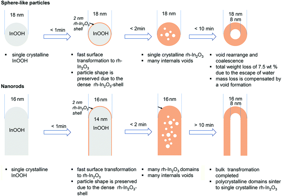
High-resolution real-time in situ studies of single nanoparticles have received increased attention in the last years. A few examples are X-ray microscopic imaging of silver nanowire hollowing kinetics,1 microscopic observation of shape evolution of gold nanocrystals,2 tip-enhanced Raman spectroscopic mapping of catalytic reactions on single Pt particles,3 microscopic imaging of hydroxide to oxide decomposition in single nanocubes4 and microscopic studies of the oxidation of single Fe nanoparticles.5 Hollow nanosized particles and tubes are of interest for fundamental studies and diverse applications such as catalysis, nanoelectronics, gas sensors, and medical applications.6–10High-resolution electron microscopy is one of the methods widely applied for studying single nanocrystals (see e.g.ref. 1, 2, 4 and 5) since it allows for direct imaging of their phase and shape evolution over time. An appearance of voids in metal oxides synthesized by the decomposition of the hydroxylated phases (oxyhydroxides, hydroxides) under a thermal treatment was previously reported for many systems; among them, the dehydroxylation of goethite to hematite, α-FeOOH to α-Fe2O3, and a diaspore to corundum, α-AOOH to α-Al2O3, are the most widely studied reactions, assessed directly in the microscope. For example, the in situ dehydroxylation of diaspore induced by an electron beam results in mesoporous transition alumina phases;11,12 goethite crystals transforms into a mosaic of highly oriented hematite crystallites (<5 nm across) separated by pairs of slit-shaped micropores (0.8 nm wide) running along the goethite needle axis which act as channels for water escape.13,14–16,17 In contrast to large crystals, i.e. slightly sub-micron-sized crystals, which disaggregate during thermal treatment/under electron (e)-beam irradiation, nanocrystals behave differently in several aspects. Paradoxically, the transformed oxide specimens retain the morphology of the starting materials and remain single crystals after the transformation, but with an internal void in the middle/center of the transformed spheres/rods.
In this context, our study provides an insight into the mechanism of these transformations clarifying controversial and paradoxical findings and underlines the complex interplay between phase and shape evolution. We take the decomposition of InOOH into corundum-type metastable rh-In2O3 as a model reaction to study the void formation in individual dense/solid single crystalline particles and rods. It allows also for a comparison to similar transformations in the aforementioned systems, revealing similarities to other corundum-type oxides, i.e. hematite and corundum itself, and for a desired synthesis of hollow nanostructures. The synthesis of hollow nanostructures has extensively been reviewed in the literature since 1998 when Caruso et al. reported a template-based synthesis approach for hollow silica spheres.18 Typically, the synthesis approaches towards hollow materials are differentiated between templating (i.e. hard, sacrificial and soft) and template-free methods.19,20 In our case, this transformation happens in situ in the electron microscope allowing for a desired manipulation of the material structure and morphology at the nanoscale.
Results
InOOH nanospheres are synthesized solvothermally as described in detail elsewhere;21 Fe-doped InOOH nanorods are obtained under the same conditions by adding to the starting solution iron(III) nitrate nonahydrate in the molar ratio In![[thin space (1/6-em)]](https://www.rsc.org/images/entities/char_2009.gif) :Fe = 95:5.
:Fe = 95:5.
The X-ray diffraction (XRD) patterns (Fig. 1 panel D for ex situ and B + C for in situ characterization) confirm the orthorhombic InOOH phase (P21nm, no. 31, Z = 2 units of composition within the unit cell) in both specimens. The ex situ calcination of InOOH and Fe-doped InOOH samples in air for 30 min at 375 °C and 450 °C leads to the phase-pure and iron-doped metastable corundum-type rh-In2O3 (R![[3 with combining macron]](https://www.rsc.org/images/entities/char_0033_0304.gif) c, no. 167, Z = 6 units of composition within the unit cell), respectively (Fig. 1A a–d shows HRTEM micrographs of all samples). This transformation was as well studied by time resolved in situ XRD;22 see Fig. 1B and C for the contour plots of the InOOH to rh-In2O3 transformation (Fig. SI_3 in the ESI† shows the in situ contour plots in an enlarged format). The in situ XRD characterization reveals that the phase transformation from InOOH to rh-In2O3 proceeds directly without appearance of other intermediate crystalline structures. Energy dispersive X-ray spectroscopy (EDXS) analysis reveals the same Fe:In ratio of 0.03 in both Fe-doped InOOH and rh-In2O3 materials, respectively. EDXS elemental maps based on the In–Lα1, O–Kα and Fe–Kα1 X-ray lines confirm uniform elemental distributions within particles before and after calcination (Fig. 2). No segregation of Fe-containing compounds is observed. Accordingly, in the following the iron-doped samples are denoted as In0.97Fe0.03OOH and rh-In1.94Fe0.06O3. Single XRD line-profile analysis and Rietveld refinement of the XRD data reveal that In0.97Fe0.03OOH and rh-In1.94Fe0.06O3 samples possess slightly smaller unit cell volumes in comparison with un-doped specimens (Table 1). The decrease in the unit cell volume of Fe-doped samples is due to the substitution of smaller Fe3+ for larger In3+ cations [r (Fe3+, high spin) = 64.5 pm, r (In3+) = 80 pm; both ions are sixfold coordinated].23
c, no. 167, Z = 6 units of composition within the unit cell), respectively (Fig. 1A a–d shows HRTEM micrographs of all samples). This transformation was as well studied by time resolved in situ XRD;22 see Fig. 1B and C for the contour plots of the InOOH to rh-In2O3 transformation (Fig. SI_3 in the ESI† shows the in situ contour plots in an enlarged format). The in situ XRD characterization reveals that the phase transformation from InOOH to rh-In2O3 proceeds directly without appearance of other intermediate crystalline structures. Energy dispersive X-ray spectroscopy (EDXS) analysis reveals the same Fe:In ratio of 0.03 in both Fe-doped InOOH and rh-In2O3 materials, respectively. EDXS elemental maps based on the In–Lα1, O–Kα and Fe–Kα1 X-ray lines confirm uniform elemental distributions within particles before and after calcination (Fig. 2). No segregation of Fe-containing compounds is observed. Accordingly, in the following the iron-doped samples are denoted as In0.97Fe0.03OOH and rh-In1.94Fe0.06O3. Single XRD line-profile analysis and Rietveld refinement of the XRD data reveal that In0.97Fe0.03OOH and rh-In1.94Fe0.06O3 samples possess slightly smaller unit cell volumes in comparison with un-doped specimens (Table 1). The decrease in the unit cell volume of Fe-doped samples is due to the substitution of smaller Fe3+ for larger In3+ cations [r (Fe3+, high spin) = 64.5 pm, r (In3+) = 80 pm; both ions are sixfold coordinated].23
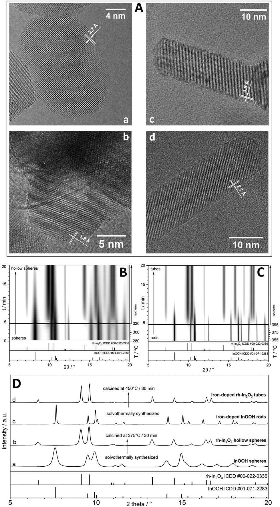 | ||
| Fig. 1 (A) HRTEM micrographs of (a) InOOH spheres, (c) Fe-doped InOOH rods before calcination; (b) rh-In2O3 hollow spheres and (d) Fe-doped rh-In2O3 tubes obtained upon calcination of the respective InOOH samples. (B) and (C): Time resolved in situ XRD contour plots of transformation during heating and isothermal holding of (B) InOOH spheres to rh-In2O3 hollow spheres at 320 °C and (C) of Fe-doped InOOH rods to rh-In2O3 tubes at 395 °C. (D) XRD patterns of all four samples before and after ex situ calcination at 375 °C and 450 °C respectively. | ||
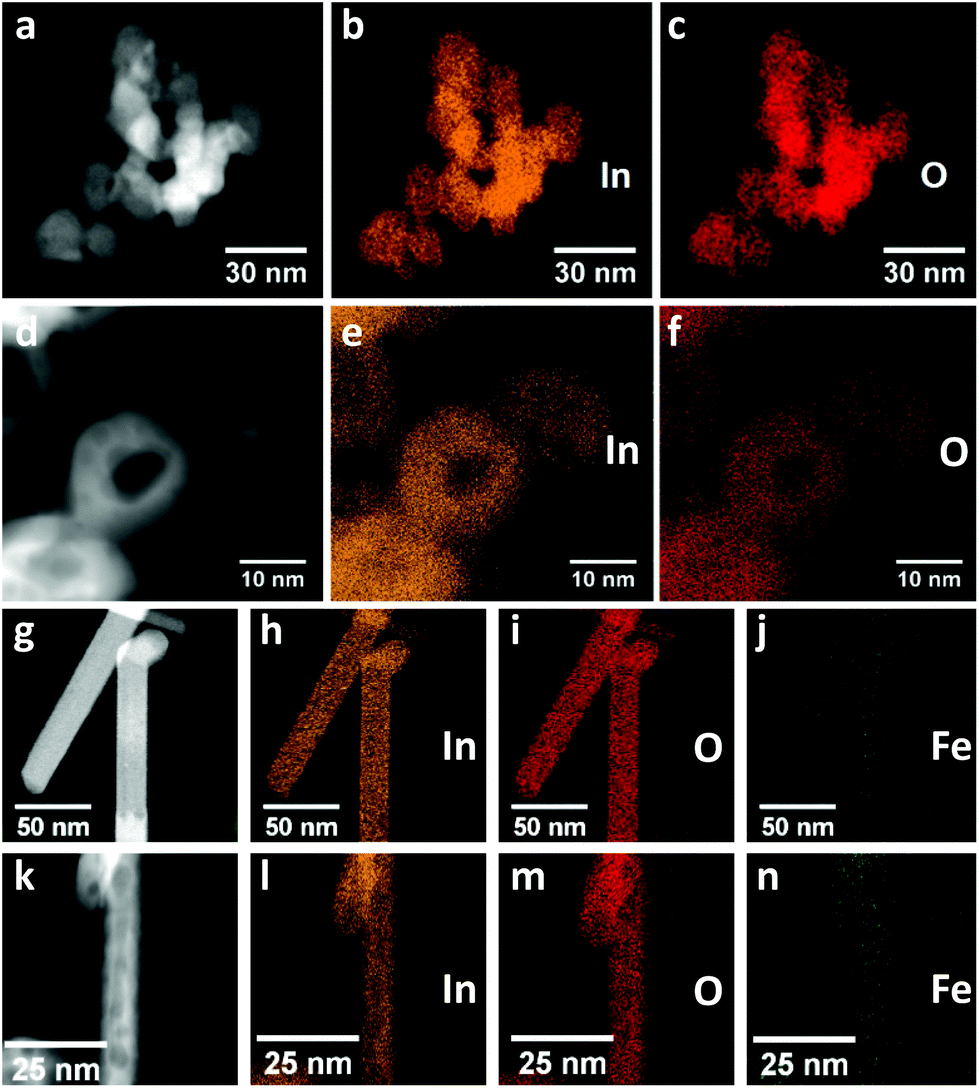 | ||
| Fig. 2 (a–c) InOOH nanoparticles before and (d–f) hollow rh-In2O3 nanoparticles after calcination. (a and d) High-angle annular dark-field field scanning transmission electron microscopy (HAADF-STEM) images and EDXS elemental maps of the In-Lα1 (orange, b and e) and O–Kα (red, c and f) X-ray lines. (g–j) InOOH nanorods before and (k–n) rh-In2O3 nanotubes after calcination. (g and k) HAADF STEM images and EDXS elemental maps of In-Lα1 (orange, h and l), O–Kα (red, i and m) and Fe-Kα1 (blue, j and n) X-ray lines. The intensity of X-ray lines indicates uniform elemental distributions within nanoparticles. | ||
| InOOH [ref. 24] | rh-In2O3 [ref. 26] | InOOH spheres | rh-In2O3 hollow spheres | Fe-InOOH rods | rh-FeIn2O3 tubes | |
|---|---|---|---|---|---|---|
| a [Å] | 5.26 | 5.487 | 5.29 ± 0.02 | 5.49 ± 0.01 | 5.27 ± 0.01 | 5.48 ± 0.01 |
| b [Å] | 4.56 | — | 4.57 ± 0.02 | — | 4.57 ± 0.01 | — |
| c [Å] | 3.27 | 14.510 | 3.27 ± 0.01 | 14.51 ± 0.01 | 3.28 ± 0.01 | 14.50 ± 0.01 |
| Vol cell [Å3] | 78.43 | 378.33 | 79.05 ± 0.52 | 378.74 ± 1.01 | 79.00 ± 0.33 | 377.43 ± 1.01 |
| V/In [Å3] | 39.22 | 31.53 | 39.53 ± 0.26 | 31.56 ± 0.08 | 39.50 ± 0.16 | 31.45 ± 0.08 |
| D TEM [nm] | 18 ± 4 | 18 ± 4 | 18 ± 5 | 18 ± 5 | ||
| d TEM [nm] | — | 8 ± 2 | — | 8 ± 3 | ||
| D XRD [nm] | 13 ± 3 | 14 ± 4 | — | — | ||
| d XRD [nm] | 8 ± 2 | |||||
| L TEM [nm] | 30–576 | 28–573 |
TEM reveals that InOOH and In0.97Fe0.03OOH samples consist of uniform dense sphere-like (Fig. 1a) and rod-like (Fig. 1c) nanoparticles, respectively. Both are single crystals as confirmed by continuous lattice fringes extending through the whole nanoparticles. Average fringe distances of 2.7 ± 0.1 Å and 3.5 ± 0.1 Å are observed in the InOOH nanospheres (Fig. 1a) and In0.97Fe0.03OOH nanorods (Fig. 1c), respectively, corresponding to the (011) and (110) plane distances in InOOH.24 The Fourier transform (FT) of the HRTEM images is in good agreement with calculated diffraction patterns of the orthorhombic InOOH structure (Fig. SI_1a,b and SI_2a,b†) and confirms that the nanoparticles are mono-crystalline.
The most intriguing change induced by the annealing is found by a comparison of the starting material with the transformed specimens. Voids are formed in the transformed spheres (Fig. 1b) and tubes (Fig. 1d) which retain the morphology and size of the starting materials and remain single crystals after the transformation. A phase transformation into rh-In2O3 takes place which is verified by the agreement of the FT of the HRTEM images with calculated diffraction patterns of rh-In2O3 (Fig. SI_1c,d and SI_2c,d†).
Average nanoparticle sizes are determined for each sample by fitting the lognormal distribution function25 to the experimental distribution derived by the TEM analysis of about 700 particles located on different HRTEM images (details are given in ESI and Fig. SI_4†). This yields an average diameter of DTEM = 18 ± 4 nm for the InOOH nanospheres. The same average outer diameter is measured for the hollow rh-In2O3 particles after transformation while their voids have an average size of dTEM = 8 ± 2 nm. The average diameter of the In0.97Fe0.03OOH nanorods determined from their experimental distribution is DTEM = 18 ± 5 nm, which also remains unchanged after transformation into tubes with an inner diameter dTEM of 8 ± 3 nm. All data including rod/tube lengths are compiled in Table 1.
The transition from solid to hollow particles is studied by a time-resolved series of HRTEM images recorded from the same nanoparticle to monitor the structure transformation in situ under continuous illumination with 300 keV electrons in a transmission electron microscope. All microscope alignments are performed on sample regions, which are not considered for data collection. After moving the sample to the area of interest, refocusing is necessary, which takes approximately 20 s.
The solid-to-hollow nanoparticle transition was investigated using an electron dose rate of 1.04 × 10⁶ e nm−2 s−1 and a beam current of 9.7 nA (Fig. 5). A slightly smaller dose rate of 0.89 × 10⁶ e nm−2 s−1 and a beam current of 9.6 nA were used for the nanorod–nanotube transition (Fig. 4). By illuminating a sample with electrons, energy will be transferred to the sample by inelastic scattering leading to a temperature rise. The temperature increase can only be calculated in a coarse approximation and is expected to amount to ΔT ≈ 10 °C (nanorods) and ΔT ≈ 12 °C (nanoparticles) (for detailed calculations, see ESI†). This indicates the minor role played by the temperature increase in the electron-beam induced phase and morphological transition of nanoparticles/nanorods, which will be shown in the following. The phase and morphological transitions observed in situ in the transmission electron microscope are driven by knock-on processes due to elastic electron–atom collisions; also, breaking of bonds is involved.4 The observed transitions can therefore be described as an electron beam induced decomposition process, which is the combined result of knock-on and radiolysis. The average atom residence time on their sites is calculated to be between 22 s and 84 s (for details see ESI†), which promotes reorganization of atoms during the phase transition and void formation.
The structural phase transition is further analyzed by calculating Fourier-filtered images. This requires to Fourier-transform the original HRTEM image. A Bragg reflection (hkl) of the crystal structure of interest is then selected in the corresponding FT by using a circular aperture with a diameter equal to the half of the minimal distance up to its neighboring Bragg reflections. After artificial intensity enhancement of the selected reflection, an inverse FT is calculated by taking only the selected reflection into account (see ESI† for further details). The Fourier-filtered (FF) image reveals the size and location of regions with the crystal structure of interest and is used to selectively enhance the contrast of crystalline domains with either the orthorhombic InOOH or rh-In2O3 phase. The procedure allows for a direct visualization of crystalline domains belonging to each of the two phases involved in the phase transition and the location of these regions on the nanoparticles. In Fig. 3 the intensity of the (![[1 with combining macron]](https://www.rsc.org/images/entities/char_0031_0304.gif) 20) reflection for InOOH (d(−1 2 0) = 2.09 Å) and the (20
20) reflection for InOOH (d(−1 2 0) = 2.09 Å) and the (20![[4 with combining macron]](https://www.rsc.org/images/entities/char_0034_0304.gif) ) reflection for rh-In2O3 (d(2 0 −4) = 1.99 Å) were selected and artificially increased by a factor of 20 to visualize the respective phases.
) reflection for rh-In2O3 (d(2 0 −4) = 1.99 Å) were selected and artificially increased by a factor of 20 to visualize the respective phases.
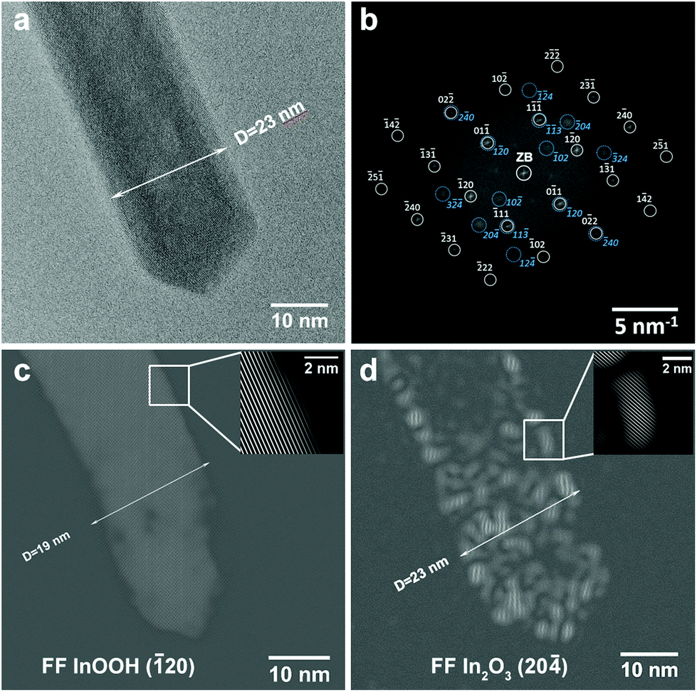 | ||
| Fig. 3 In0.97Fe0.03OOH rod tip after 20 s illumination time with the 300 keV electrons: (a) HRTEM image, (b) FT of (a) showing that the rod is a mixture of the orthorhombic InOOH (gray circles and indices) and the rh-In2O3 (blue circles and indices) mono-crystalline phases, (c) FF image using the (−1 2 0) reflection of the InOOH structure. The inset shows lattice fringes with an average distance of d = 2.2 Å, corresponding to d(−1 2 0) = 2.09 Å in InOOH; and (d) FF image using the (2 0 −4) reflection of the rh-In2O3 structure. The inset shows lattice fringes with an average distance of d = 2.0 Å, corresponding to d(2 0 −4) = 1.99 Å in rh-In2O3. | ||
The tip of an In0.97Fe0.03OOH nanorod is displayed after 20 s illumination with the electron beam (electron dose 1.8 × 10⁷ e nm−2) (Fig. 3) and after further illumination time intervals of 6, 18 and 30 min (Fig. 4). The In0.97Fe0.03OOH nanorod with a diameter of 23 nm does not contain any voids after 20 s electron illumination (Fig. 3a). The FT pattern of the rod tip in the HRTEM image in Fig. 3b shows that the rod consists of two single-crystalline phases: (i) single-crystalline orthorhombic InOOH (P21nm, no. 31, with a = 5.26 Å, b = 4.56 Å and c = 3.27 Å) in the [211]-zone axis (grey symbols and Miller indices) and (ii) single-crystalline rh-In2O3 (Rc, no. 167, with a = 5.487 Å, c = 14.510 Å) in the [211]-zone axis (blue symbols and Miller indices). Considering the small Fe content of the rod/tube, which does not change the orthorhombic InOOH and rh-In2O3 structures, in the following we describe the rod/tube compositions by omitting their Fe content. FT reveals that Bragg reflections of InOOH are sharp, characteristic of large and well crystallized regions with an InOOH structure, while the diffraction spots of rh-In2O3 are quite diffuse, indicating small and distorted regions with an rh-In2O3 structure. The FF image obtained with the InOOH (20) reflection (Fig. 3c) shows that the (20) lattice fringes of the InOOH phase are aligned parallel to the rod axis, but the diameter of the rod region with the InOOH structure (Fig. 3c) is reduced to 19 nm compared to its initial value of 23 nm (Fig. 3a). The location of the rh-In2O3 structure can be deduced from the FF image obtained with the (20) reflection, which visualizes the (20) planes of the rh-In2O3 structure (Fig. 3d). These fringes are located close to the rod surface. The rod has a diameter of 23 nm (Fig. 3d) in good agreement with the rod diameter on the HRTEM image (Fig. 3a). This indicates the formation of a 2 nm thin, single-crystalline rh-In2O3 shell around the single-crystalline InOOH core with a diameter of 19 nm. We point out that, due to the projection of the surface over the core, on the FF(20) image the shell region with the In2O3 structure is extended over the whole particle. Despite an apparent random distribution of rh-In2O3 regions at the rod surface, which indicates that the InOOH to rh-In2O3 decomposition starts from multiple nucleation sites spread over the whole surface, all crystallites are well oriented with respect to each other resulting in a single-crystalline shell. Although TEM itself is not a surface sensitive method, the findings from the FF analysis of the rod tip discussed here suggest that the transformation from InOOH to rh-In2O3 starts at the surface of the rod. This demonstrates that only 20 s illumination time necessary to refocus and record the HRTEM image, i.e. an electron dose of 1.8 × 10⁷ e nm−2, is sufficient to initiate the InOOH to rh-In2O3 phase transformation.
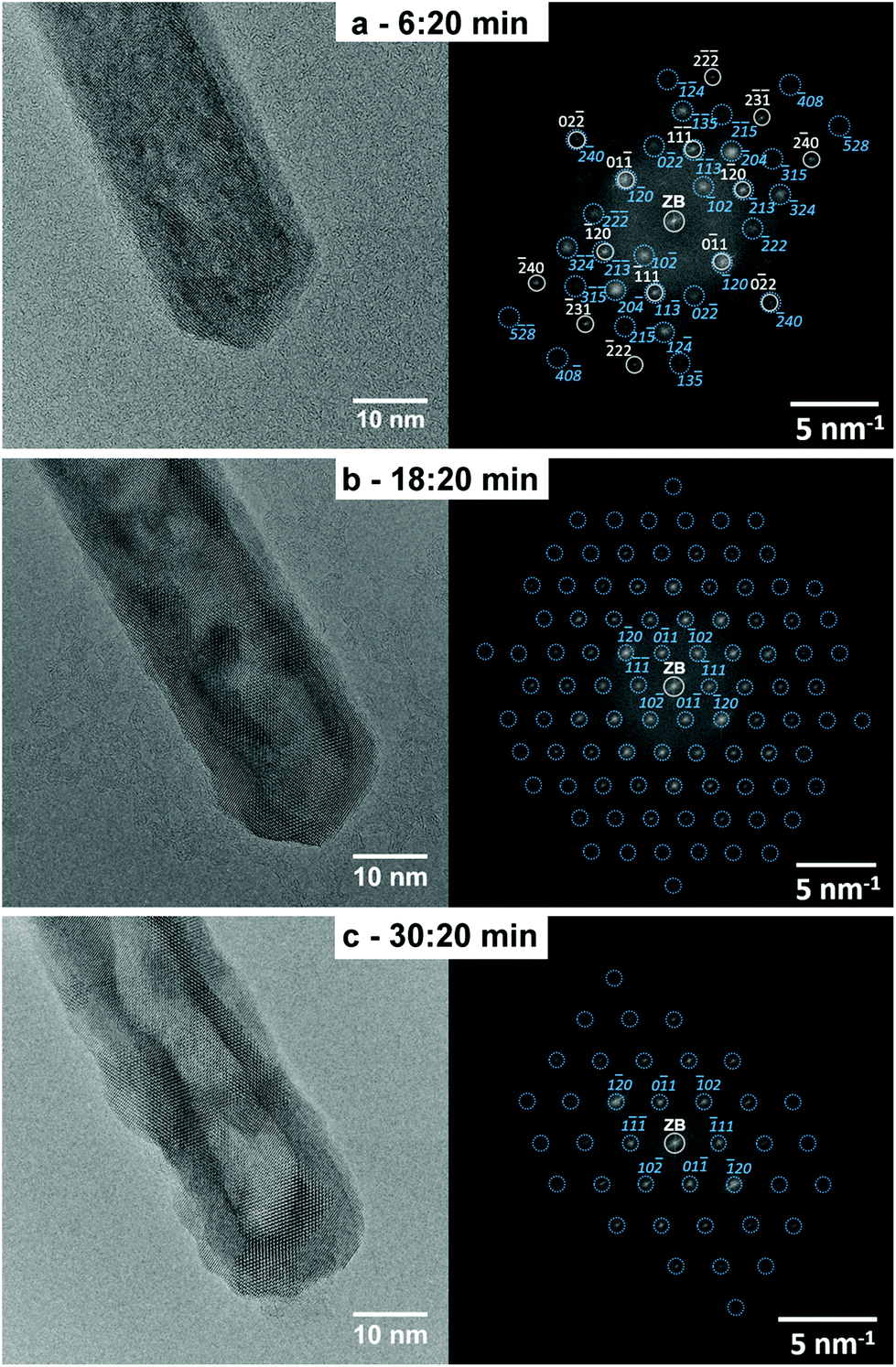 | ||
| Fig. 4 HRTEM micrographs and corresponding FT images of the same In0.97Fe0.03OOH rod shown in Fig. 3 after further illumination with 300 keV electrons in a transmission electron microscope. (a) After 6 min and 20 s, the rod consists of a mixture of the orthorhombic InOOH (space group P21nm, No. 31) and rh-In2O3 (space group Rc, No. 167) phases. This is demonstrated by the agreement of the FT of the HRTEM image with the calculated diffraction pattern of the orthorhombic InOOH structure in the [211]-zone axis (gray symbols and indices) and the calculated diffraction pattern of the rh-In2O3 structure in the [211]-zone axis (blue symbols and indices). After (b) 18 min and 20 s and (c) 30 min and 20 s illumination, the whole rod is single-crystalline and consists of the rh-In2O3 phase as demonstrated by the agreement between the FT images and calculated diffraction patterns of rh-In2O3 in the [211]-zone axis. For legibility reasons, only a small number of reflections are marked and indexed in the FT shown in (b) and (c). The indices of all other reflections can be deduced from the low-index reflections. | ||
With increasing electron-beam irradiation up to 6 min and 20 s, which corresponds to an electron dose of 3.4 × 10⁸ e nm−2, the morphological rod-to-tube transformation begins to become visible on the corresponding HRTEM image (Fig. 4a), which shows the formation of non-connected voids in the rod core. The FT of the HRTEM image (Fig. 4a) indicates that InOOH and rh-In2O3 are both still present as demonstrated by the agreement of their FTs with the calculated diffraction patterns of the two phases. Moreover, the FT reveals that the diffraction spots of the InOOH phase become more diffuse compared to the FT of the initial rod (Fig. 3b), but the peaks are still quite sharp, indicating the presence of relatively large, well crystallized InOOH regions in the rod core. In addition, the diffraction spots of the rh-In2O3 phase become sharper after further 6 min illumination as compared to those of the same phase after 20 s (Fig. 3b), indicating a higher degree of order and/or less strain. The FT in Fig. 4a also shows higher order Bragg reflections of the indium oxide phase compared to the FT of the initial rod (Fig. 3b). This indicates a better orientation of the rh-In2O3 shell in the [211]-zone axis, a decrease of its strain, and the increase of the monocrystalline shell (thickness) with the rh-In2O3 structure as compared with the In2O3 shell after 20 s illumination (Fig. 3b). However, the rh-In2O3 crystallites remain still small.
After 18 min and 20 s electron-beam illumination (corresponding electron dose 9.8 × 10⁸ e nm−2), the InOOH–rh-In2O3 phase transition is completed. The whole rod in the HRTEM image in Fig. 4b is a rh-In2O3 monocrystal, as indicated by the agreement between its FT and the calculated diffraction pattern. We emphasize that the rod remains single crystalline during the InOOH–rh-In2O3 phase transition. Moreover, the HRTEM image in Fig. 4b clearly reveals the morphological rod-to-tube transition where an almost empty void is formed in the center of the rod. Prolonged illumination of 30 min and 20 s (corresponding electron dose 1.6 × 10⁹ e nm−2) results in a complete rod-to-tube transition by the formation of an entirely empty canal in the middle of the rod observed by its bright contrast in the HRTEM image in Fig. 4c. The whole tube is a rh-In2O3 monocrystal as demonstrated by its indexed FT.
Our study demonstrates that monocrystalline In0.97Fe0.03OOH rods transform into monocrystalline rh-In1.94Fe0.06O3 tubes, which can be obtained either after long illumination of about 30 min by high-energy electrons in a transmission electron microscope (corresponding electron dose of 1.6 × 10⁹ e nm−2) or after the ex situ annealing in a furnace at 450 °C for 30 min.
The structural and morphological transformation from solid to hollow sphere-like nanoparticles occurs in the same way as the previously described rod-to-tube transformation. The phase transition proceeds quickly first, and the nanoparticles remain single-crystalline at any stage of the transformation. To illustrate the transformation process, Fig. 5 displays a time series of HRTEM images, which allows to monitor the transformation of a solid InOOH particle into a rh-In2O3 hollow particle induced by the illumination with 300 keV electrons. The HRTEM image of the InOOH particle in Fig. 5a was taken after 20 s illumination time (electron dose of 2.1 × 10⁷ e nm−2), necessary to refocus and record the HRTEM image. The FT of the HRTEM image (Fig. 5a) can be explained by the presence of monocrystalline InOOH in the [011]-zone axis (gray symbols and Miller indices) and monocrystalline rh-In2O3 in the [211]-zone axis (blue symbols and Miller indices).
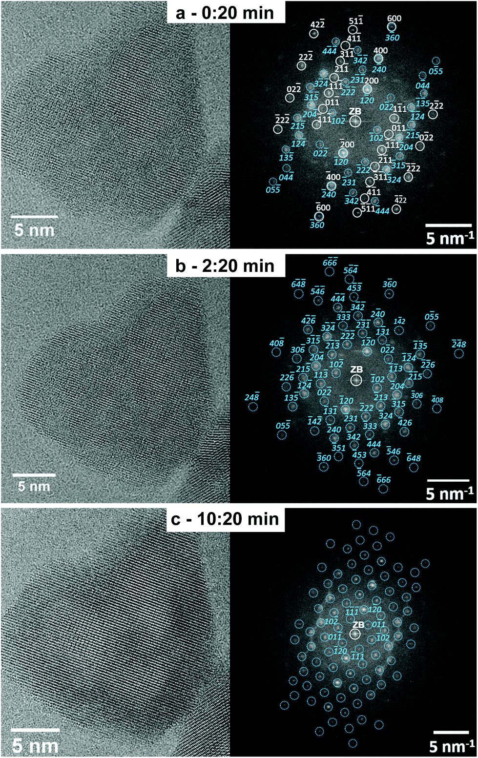 | ||
| Fig. 5 Transition of a solid InOOH into a rh-In2O3 hollow particle upon electron beam irradiation: (a) HRTEM micrograph of the InOOH particle after 20 s illumination and its FT showing that the particle is a mixture of the orthorhombic InOOH and rh-In2O3 mono-crystalline phases. The FT of the HRTEM image agrees with the calculated diffraction patterns of orthorhombic InOOH in the [011]-zone axis (gray symbols and Miller indices) and rh-In2O3 in the [211]-zone axis (blue circles and indices). HRTEM and FT of the nanoparticle after (b) 2 min and 20 s and (c) 10 min and 20 s, when the InOOH-to-rh-In2O3 phase transition is completed. The corresponding FTs show that the whole particle is composed of the monocrystalline rh-In2O3 phase in the [211]-zone axis. | ||
After 2 min and 20 s illumination with the electron beam (electron dose 1.5 × 10⁸ e nm−2), the solid-to-hollow-particle transformation starts as indicated by the appearance of first voids (HRTEM image in Fig. 5b), while the InOOH-to-rh-In2O3 phase transition is already finished as demonstrated by the good agreement of its FT and the calculated diffraction pattern of rh-In2O3 in the [211]-zone axis (Fig. 5b). Finally, a large void in the center of the nanoparticle is formed after 10 min and 20 s continuous illumination with an electron dose of 6.5 × 10⁸ e nm−2 (HRTEM image in Fig. 5c). No further phase transformation is observed. The particle maintains the rh-In2O3 structure as demonstrated by the agreement between its FT and the calculated diffraction pattern of rh-In2O3 in the [211]-zone axis (Fig. 5c, right panel).
The phase transformation of InOOH particles into rh-In2O3 hollow particles appears to start already during the short time interval of 20 s (corresponding electron dose 2.1 × 10⁷ e nm−2) necessary to refocus and acquire the first HRTEM image. Phase transformation from InOOH into rh-In2O3 is completed after illumination time intervals of between 2 min and 20 s (Fig. 5b) (electron dose of 1.5 × 10⁸ e nm−2) and 4 min (electron dose 1.7 × 10⁸ e nm−2) (see investigation of a nanoparticle ensemble in Fig. SI_5†). Further illumination with high-energy electrons results in an improvement of the hollow particle morphology without any further phase transformation.
We note that the phase and morphological transitions of the InOOH nanoparticles strongly depend on the electron dose. For example, a low electron dose rate of 0.89 × 10⁵ e nm−2 s−1 used to record overview TEM images did not lead to any phase change after illumination time intervals of up to 2–3 min (total electron dose 1.1 × 10⁷–1.6 × 10⁷ e nm−2). An increased electron dose rate of 2.5 × 10⁵ e nm−2 s−1 successfully induces a complete InOOH–rh-In2O3 phase transition. Void formation starts, but does not lead to the complete transformation of rods into tubes even after illumination time intervals of about 25 min (total electron dose 3.7 × 10⁸ e nm−2). These considerations show that the main factors, which drive the phase and morphology transformation, are the electron doses and (most likely) the electron energy that determine the average residence times of atoms on their lattice sites, besides a small local temperature increase.
Our study shows that ex situ calcination of the InOOH and Fe-doped InOOH samples in air for 30 min at 375 °C and 450 °C leads to the formation of phase-pure and iron-doped metastable corundum-type rh-In2O3 hollow particles and tubes. The same phase and morphological transformation of InOOH solid nanoparticles/nanorods into rh-In2O3 hollow nanoparticles/nanotubes can be induced in situ after continuous illumination with 300 keV electrons in a transmission electron microscope for about 30 min and 10 min, respectively. Estimates of the temperature increase induced by the electron-beam illumination yield values of only 10 and 12 degrees under our experimental conditions, which are much lower than the ex situ annealing temperatures. This indicates the minor role played by the temperature increase in the phase and morphological transition of nanoparticles/nanorods induced by the illumination with high-energy electrons. Hence, electron beam induced decomposition processes must be responsible for the reorganization of atoms at such a low temperature. This is supported by comparing the illumination time interval of only 20 s (Fig. 5 and Fig. 6), where the rh-In2O3 crystalline phase starts to be formed, with an average residence time of In and O atoms in the InOOH lattice between 22 s and 68 s (see ESI†) depending on the atom type and dose rate.
 | ||
| Fig. 6 Schematic illustration of the different stages of the InOOH-to-rh-In2O3 transformation. | ||
Electron beam induced decomposition is also expected to support water extraction despite the low temperature. The experimental electron dose rates result in an average residence time of OH (related to water formation and extraction) of between 51 s and 84 s (see ESI†). Water extraction may be further supported under the high-vacuum conditions in the transmission electron microscope because a stronger partial pressure gradient of water is expected to enhance diffusion of water molecules.
The rapid phase and morphological transition of the InOOH nanoparticles induced by electron-beam illumination within 10 min as compared to 30 min necessary for the transition of the InOOH nanorods, can be understood by the higher electron dose rate, which results in smaller residence times of atoms on the InOOH lattice sites and by the smaller nanoparticle size compared to rods, which favors the water elimination.
Furthermore, our study provides insight also into the mechanism of the void formation in solid nanoparticles and rods that finally results in hollow nanoparticles and tubes. HRTEM characterization displays a stepwise decomposition, which develops from the particle surface and protrudes towards its core for both tubes and spherical particles. The initial formation of the rh-In2O3 shell at the particle surface assures the preservation of the particle morphology, shape and size, which is explained by taking into account the following features of the system under study:
(1) The InOOH-to-rh-In2O3 transformation goes along with densification because rh-In2O3 (7.311 g cm−3) is denser than the orthorhombic InOOH (6.258 g cm−3) phase. Such a densification process developing from the surface into the bulk results in the formation of a void/an empty canal in the middle of the sphere/tube because the original shape is maintained by the firstly formed rh-In2O3 shell. Based on that, the preservation of the particle size during the InOOH-to-rh-In2O3 transformation can be explained.
(2) HRTEM shows that, despite a significant mass loss of about 7.5 wt% due to the escape of water (see Fig. 11 in ref. 21 for differential thermal analysis (DTA) of the sample under investigation), the particle size does not change during the InOOH-to-rh-In2O3 transformation. The mass loss is compensated by the formation of an internal void, which is understood if we consider the space required to accommodate the structural unit in each phase. Indium atoms require less space in rh-In2O3 than in InOOH. Indeed, in the InOOH structure 39.2 Å3 per indium is available, while the rh-In2O3 structure provides only 31.5 Å3 per indium atom. When the InOOH particle transforms into the rh-In2O3 structure with a loss of 7.5 wt% due to the escape of water, the volume of the particle should decrease by a factor of 39.2/31.5. The measured contraction factors 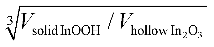 of 1.031 ± 0.033 for the spherical particles and 1.075 ± 0.264 and 1.052 ± 0.381 for the rod-like particles of maximum and minimum length, respectively, are close to the theoretical value of 1.076. For details concerning the calculation of the contraction factors, see the ESI.†
(3) A common feature for spheres and tubes is the development of microporosity upon dehydroxylation due to the expulsion of water. At longer irradiation times (and at higher dehydroxylation temperatures), the micropores coalesce as the result of an internal pressure of heated water vapor which is prevented from escaping the voids and their shape becomes symmetrical and uniform which is similar to previous findings.15 A significantly larger internal pressure in large crystals causes their disaggregating into small subunits/domains wherein small nanosized crystals remain intact.
As the transformed crystals retain the same size, one has to note a significant difference in the transformation mechanism attributed to the nano-Kirkendall effect typically observed in the oxidation of metallic nanoparticles (see e.g.ref. 5), in which an increased crystal size results from material (i.e. metal cation) transport outwards across the interface. In our case, a short-range migration of hydrogen atoms leads to the OH-groups which coalesce/diffuse outwards and leave particles as water molecules. This mechanism is similar to the one previously suggested for the goethite to hematite transformation.13,27 Consequently, due to the proton transfer across the reaction interface, the matter transferred outwards is removed in the form of water, leading to void formation inside without an increase of the particle size.
Conclusions
In conclusion, the mechanisms of void formation in solid single crystalline spherical and rod-like particles during the dehydroxylation of InOOH nanoparticles into rh-In2O3 have been evaluated comprehensively in this work. The time-resolved in situ synchrotron XRD experiments and in situ TG-DTA characterization studies show that the dehyroxylation of the InOOH spheres and the Fe-doped InOOH rods starts at 320 °C and 395 °C, respectively, leading to the formation of metastable corundum-type rh-In2O3 with a significant mass loss of about 7.5 wt% due to the escape of water. The ex situ HRTEM and XRD characterization studies confirmed the formation of phase-pure rh-In2O3 hollow spheres and iron-doped rh-In2O3 nanotubes by the ex situ calcination of InOOH and Fe-doped InOOH samples in air for 30 min at 375 °C and 450 °C, respectively. The time-resolved high-resolution transmission electron microscopy (HRTEM) experiments reveal that electron beam induced decomposition is capable also of causing the same phase and morphology transformation. A fast InOOH to rh-In2O3 transformation, accompanied by the formation of several small voids within the particle/rod center due to the expulsion of water, was found to take place after a short irradiation time. At longer irradiation times, these small voids coalesce to form a large symmetrical and uniform hollow space/canal. The mechanism responsible for the formation of hollow rh-In2O3 nanoparticles from the monocrystalline InOOH nanoparticles cannot be described by the nano-Kirkendall effect, but rather by mechanisms as observed in the goethite to hematite transformation: the initially formed oxide phase encapsulates the yet untransformed hydroxylated phase; consequently, the size of the obtained oxide crystals after completing the transformation retains the same size of the initial oxyhydroxide nanoparticles.This work will allow us to understand the phenomenology and the role of electron beam induced decomposition processes on the mechanism of the decomposition of several hydroxides and oxyhydroxides such as FeOOH,15 AlOOH,11 Al(OH)312 and In(OH)3.4 Oxyhydroxides tend to form hollow oxide structures upon decomposition (e.g. Fe2O3, Al2O3, In2O3) while a previous work in In(OH)3 showed that this hydroxide disintegrates into several small nanocrystallites during the decomposition.4 Since the formation of hollow structures is observed in several oxides with the corundum-type structure, questions about the structural reasons arise. This could be a topic of further – more basic – crystallographic studies. Furthermore, the careful control and optimization of electron energy, dose and dose rate, which together are responsible for electron beam induced decomposition, represents another interesting way to produce hollow nanoparticles. This method can potentially be better controlled than conventional thermal decomposition processes and could provide promising materials for several emerging applications such as energy storage and conversion and drug release.
Conflicts of interest
There are no conflicts to declare.Acknowledgements
The authors thank the Advanced Light Source ALS (which is supported by the Director, Office of Science, Office of Basic Energy Sciences, of the U.S. Department of Energy under Contract No. DE-AC02-05CH11231), where in situ PXRD measurements were conducted at beamline 12.2.2 in the framework of AP program ALS-08865. LS appreciates the ALS for supporting his work with a doctoral fellowship. The authors thank also the KNMF (Karlsruhe Nano Micro Facility at Karlsruhe Institute of Technology, KIT) for financially supporting the TEM investigations.References
- L. Yu, Z. Y. Yan, Z. H. Cai, D. T. Zhang, P. Han, X. M. Cheng and Y. G. Sun, Nano Lett., 2016, 16, 6555–6559 CrossRef CAS PubMed.
- X. C. Ye, M. R. Jones, L. B. Frechette, Q. Chen, A. S. Powers, P. Ercius, G. Dunn, G. M. Rotskoff, S. C. Nguyen, V. P. Adiga, A. Zettl, E. Rabani, P. L. Geissler and A. P. Alivisatos, Science, 2016, 354, 874–877 CrossRef CAS PubMed.
- C. Y. Wu, W. J. Wolf, Y. Levartovsky, H. A. Bechtel, M. C. Martin, F. D. Toste and E. Gross, Nature, 2017, 541, 511–515 CrossRef CAS PubMed.
- G. Miehe, S. Lauterbach, H. J. Kleebe and A. Gurlo, J. Solid State Chem., 2013, 198, 364–370 CrossRef CAS.
- Y. Sun, X. Zuo, S. K. R. S. Sankaranarayanan, S. Peng, B. Narayanan and G. Kamath, Science, 2017, 356, 303–307 CrossRef CAS PubMed.
- X. Wang, J. Feng, Y. Bai, Q. Zhang and Y. Yin, Chem. Rev., 2016, 116, 10983–11060 CrossRef CAS PubMed.
- J. Park, T. Kwon, J. Kim, H. Jin, H. Y. Kim, B. Kim, S. H. Joo and K. Lee, Chem. Soc. Rev., 2018, 47, 8173–8202 RSC.
- Y. Yao, F. X. Ji, M. L. Yin, X. P. Ren, Q. Ma, J. Q. Yang and S. F. Liu, ACS Appl. Mater. Interfaces, 2016, 8, 18165–18172 CrossRef CAS PubMed.
- C.-Y. Lai, B. G. Trewyn, D. M. Jeftinija, K. Jeftinija, S. Xu, S. Jeftinija and V. S. Y. Lin, J. Am. Chem. Soc., 2003, 125, 4451–4459 CrossRef CAS PubMed.
- H. Jiang, T. Wang, L. Wang, C. Sun, T. Jiang, G. Cheng and S. Wang, Microporous Mesoporous Mater., 2012, 153, 124–130 CrossRef CAS.
- H. Arami, M. Mazloumi, R. Khalifehzadeh, S. Khatiboleslam and S. K. Sadrnezhaadw, J. Am. Ceram. Soc., 2007, 90, 3311–3313 CrossRef CAS.
- Y. M. Kim, S. Lee, Y. S. Kim, S. H. Oh, Y. J. Kim and J. Y. Lee, Scr. Mater., 2008, 59, 1022–1025 CrossRef CAS.
- C. J. Goss, Mineral. Mag., 1987, 51, 437–451 CrossRef CAS.
- F. Watari, P. Delavignette and S. Amelinckx, J. Solid State Chem., 1979, 29, 417–427 CrossRef CAS.
- F. Watari, P. Delavignette, J. Vanlanduyt and S. Amelinckx, J. Solid State Chem., 1983, 48, 49–64 CrossRef CAS.
- F. Watari, J. Vanlanduyt, P. Delavignette and S. Amelinckx, J. Solid State Chem., 1979, 29, 137–150 CrossRef CAS.
- D. Walter, G. Buxbaum and W. Laqua, J. Therm. Anal. Calorim., 2001, 63, 733–748 CrossRef CAS.
- F. Caruso, R. A. Caruso and H. Mohwald, Science, 1998, 282, 1111–1114 CrossRef CAS PubMed.
- X. W. Lou, L. A. Archer and Z. C. Yang, Adv. Mater., 2008, 20, 3987–4019 CrossRef CAS.
- X. J. Wang, J. Feng, Y. C. Bai, Q. Zhang and Y. D. Yin, Chem. Rev., 2016, 116, 10983–11060 CrossRef CAS PubMed.
- L. Schlicker, M. F. Bekheet and A. Gurlo, Z. Kristallogr. – Cryst. Mater., 2017, 232, 129–140 CAS.
- A. Doran, L. Schlicker, C. M. Beavers, S. Bhat, M. F. Bekheet and A. Gurlo, Rev. Sci. Instrum., 2017, 88, 013903 CrossRef CAS PubMed.
- R. D. Shannon, Acta Crystallogr., Sect. A: Cryst. Phys., Diffr., Theor. Gen. Crystallogr., 1976, 32, 751–767 CrossRef.
- M. S. Lehmann, F. K. Larsen, F. R. Poulsen, A. N. Christen and S. E. Rasmusse, Acta Chem. Scand., 1970, 24, 1662–1670 CrossRef CAS.
- N. C. Popa and D. Balzar, J. Appl. Crystallogr., 2002, 35, 338–346 CrossRef CAS.
- C. T. Prewitt, R. D. Shannon, D. B. Rogers and A. W. Sleight, Inorg. Chem., 1969, 8, 1985–1993 CrossRef CAS.
- W. J. Zhang, C. F. Huo, G. Feng, Y. W. Li, J. G. Wang and H. J. Jiao, J. Mol. Struct.: THEOCHEM, 2010, 950, 20–26 CrossRef CAS.
Footnote |
| † Electronic supplementary information (ESI) available. See DOI: 10.1039/c9nr02115a |
| This journal is © The Royal Society of Chemistry 2019 |