DOI:
10.1039/C8NJ05093G
(Paper)
New J. Chem., 2019,
43, 348-355
Catalytic performance of graphene quantum dot supported manganese phthalocyanine for efficient oxygen reduction: density functional theory approach
Received
7th October 2018
, Accepted 26th November 2018
First published on 26th November 2018
Abstract
We investigate the catalytic performance of manganese phthalocyanine, as well as manganese phthalocyanine functionalized with a graphene quantum dot matrix, in oxygen-reduction reactions from a thermodynamic perspective. Associative mechanism is found to be energetically favored over the dissociative mechanism for the entire oxygen-reduction reaction process, in both the manganese phthalocyanine and manganese phthalocyanine/graphene quantum dot systems. The initial reduction reaction that forms OOH* is the rate-determining step with reaction barriers of 0.96 eV and 0.83 eV for the manganese phthalocyanine and manganese phthalocyanine/graphene quantum dot systems, respectively. In addition, we perform density of state analyses and construct Gibbs free-energy diagrams for each intermediate step in the overall oxygen-reduction reaction process for both systems, which reveal that the inclusion of the graphene quantum dot increases the number of transferred electrons in the manganese phthalocyanine. Interestingly, the highest operating potential of the manganese phthalocyanine/graphene quantum dot system is higher than that of pristine manganese phthalocyanine. We conclude that the manganese phthalocyanine functionalized with the graphene quantum dot matrix has improved oxygen-reduction reaction activity compared to that of pristine manganese phthalocyanine, and is a potential candidate for use in polymer electrolyte membrane fuel cells.
Introduction
Growing worldwide demand for energy has shown the development of energy-storage and conversion technologies accelerate. Among various technologies, the polymer electrolyte membrane fuel cell (PEMFC) is a potential device that only produces water as a waste product.1–4 To date, the PEMFC5–7 has provided a potential solution to overcome issues that cause climate change. The catalyst layer, where the electrochemical reactions take place, is a crucial component of a PEMFC. Over the past few decades, platinum-group metals (PGMs) have been employed to facilitate oxidation–reduction (redox) reactions,8,9 in particular, hydrogen oxidation (oxygen reduction) at the anode (cathode). As PGMs are scarce, the amounts used are extremely important for determining the price as well as the performance of the catalyst layer. The United States Department of Energy (DOE) reported10 that the price of the platinum-based catalyst is responsible for virtually half of the fuel cell cost. Consequently, the catalyst layer represents a crucial bottleneck to improving the cost-effectiveness and lifetime of PEMFCs for automotive applications.11,12 Hence, to become cost-effective, PEMFCs need to overcome the barriers associated with the high costs of PGM-based catalysts.13–17 Over the past few decades, a cost-effective class of catalyst that uses non-precious metals (NPMs)18–20 has been attracted in fuel-cell research.
In addition, the current density produced by the oxygen-reduction reaction (ORR) is around 10−10 A cm−2, which is lower than the ∼10−3 A cm−2 produced by the hydrogen-oxidation reaction (HOR) in a general PEMFC device.21 Therefore, the ORR is the major reason for the power loss in fuel cells. The operating standards and assessment methodologies need to be clarified in order for improving the ORR. For instance, Gasteiger et al.22 reported two main parameters for comparing activities between catalysts: (1) the turnover frequency (TOF), which is the turnover/unit time, and (2) the number of an active site/unit volume. During the recent evolution of non-PGM catalysts, Wang et al.23 proposed possible candidates that included noble/non-noble metal electrodes and organometallic complexes. They also found that non-PGMs, significantly manganese, nickel, iron, and cobalt, among others, can be used in the design of highly efficient non-platinum catalysts owing to their low prices and natural abundances compared to Pt. These aforementioned metals have been used in non-precious-metal macrocyclic complexes, including nitrides, phthalocyanines, and chalcogenides, among others.24 As early as 1964, Jasinski et al.25 reported oxygen-reduction electrocatalysis for cobalt phthalocyanine (CoPc) complexes. They demonstrated that CoPc exhibits ORR activity under alkaline conditions. Subsequently, the electrocatalytic activities of other macrocyclic N4-complexes, such as porphyrins and phthalocyanines with various non-PGM metals, were evaluated.26 Metallophthalocyanine (MPc) complexes are attractive since their electrocatalytic performance can be tuned by using the different transition metal, the structure of the complex, the C-support matrix, and the oxidant that affects the outcome of the oxidation. Lyons et al.27 found that MPcs (M = Cr, Mn, and Fe) catalyze the selective oxidation of isobutane to tert-butanol at 80 °C. In addition, they also showed that iron perfluorophthalocyanine (Fe(FPc)) azides exhibit high catalytic activities for propane oxidations at temperatures of 125–150 °C in air at a pressure of 1000 psig. Ghani et al.28 subsequently reported that MPcs (M = Co, Cu, Fe, Mg, Mn, Ni, Sn, or Zn) were active in acidic solvents such as acetic acid, formic acid, phosphoric acid, trifluoroacetic acid, and, in particular, sulfuric acid. Meier et al.29 found that carbon–Teflon/FePcs in H2SO4 solvent produced current densities of 20–80 mA cm−2 at 0.65–0.85 V. More recent PEMFC investigations were reported by Sorokin et al.,30 in which they conclude that phthalocyanine metal complexes exhibit a variety of downsizing capabilities for forming a wide range of C–C and C–N bonds. Tuning the metal centers or the electronic properties of the phthalocyanine ligands facilitates this reaction. Furthermore, carbon carriers that have porous structures can improve catalytic ORR activity. Chen et al.31 examined the ORR of FePc and CoPc catalysts supported on carbon in 0.1 M NaOH through both experimental and computational studies. They showed that the two different ORR pathways (2e− and 4e−) are differentiated by the formation of H2O2. They concluded that the O2-adsorption and OH-adsorption energies are the critical factors that determine catalytic activity and stability, respectively.31 Moreover, Broicher et al.32 found that the ordered mesoporous manganese phthalocyanine-based materials show a good electrocatalytic activity with the overpotential of 490–590 mV at 10 mA cm−2, although a short-term stability (less than 400 s) is observed for oxygen evolution reactions (OERs). In addition, among available C-supporting materials, graphene quantum dots (GQDs) have been widely examined owing to their outstanding properties that include lack of toxicity, chemical and physical stability, ease of synthesis,33 and especially, their high surface areas that improve electrocatalytic activity. Koh et al.34 synthesized a graphene quantum-dot-supported iron(II) phthalocyanine (FePc/GQD) and found this system to be promising catalyst for PEMFCs. Besides, Kaare et al.35 compared the ORR performance of multi-walled carbon nanotubes (MWCNTs)-supported manganese phthalocyanine (MnPc) with the performance of MWCNTs-supported copper phthalocyanine (CuPc) at four different temperatures of 400, 600, 800, and 1000 °C. They found that the highest catalytic performance of both CuPc/MWCNT and MnPc/MWCNT for ORRs was achieved at 800 °C and this catalytic activity of CuPc/MWCNT was lower than that of MnPc/MWCNT system. Similarly, carbon nanotubes, graphitized carbon black, and graphene have been employed as supporting matrix layers.31,36,37
For a comprehensive analysis in terms of the influence of the carbon-support layer on ORR activity in a PEMFC, we investigated the catalytic performance of both a MnPc monolayer and a GQD-supported MnPc. MnPc/GQD complex formation may be straightforward due to a nearly flat structure of a MnPc layer. In addition, MnPc has a small HOMO–LUMO gap compared to the other MPcs, such as FePc, CoPc, NiPc, and CuPc.38
Computational details
In this study, DFT+U39 calculations were carried out using the Vienna Ab Initio Simulation Package (VASP)40,41 with Grimme's most recent dispersion corrections (DFT-D3) with Becke–Johnson damping (BJ) for van der Waals interactions42 and a U parameter of 3.9 eV43 for Mn. Since the van der Waals corrections to understand the interactions between low-dimensional systems44 and metallophthalocyanines45 are important, we used the Grimmes's dispersion corrections.42 We also selectively adds the U value of 3.9 eV for Mn atom from Ceder's work43 to correctly reproduces the energy on localized electron states. The generalized gradient approximation (GGA) in the form of the Perdew–Burke–Ernzerhof (PBE) functional46 was used. The GGA-PBE functional reasonably well described the carbon-based systems.47–52 The isolated MnPc and GQD matrix were first optimized, after which, using these structures as initial geometries, a MnPc monolayer was added to the center of an aligned parallel matrix sheet, and the entire structure was fully optimized. The adsorption of MnPc on GQD matrix was carried out in a cubic lattice of 30 × 30 × 30 Å with periodic boundary conditions (PBCs). The vacuum along the z direction was set to 26.4 Å to prevent the interaction beyond the PBCs. The dipole correction53 along the z-axis is applied to the system. Moreover, the energy- and force-convergence criteria of 10−5 eV and 0.02 eV Å−1, respectively, and a cutoff energy of 400 eV; 2 × 2 × 2 and 4 × 4 × 4 k-points were used to represent the Brillouin zone using the Monkhorst–Pack54 scheme during the optimization procedures and density-of-state (DOS) calculations, respectively.
Results and discussion
Optimized structure
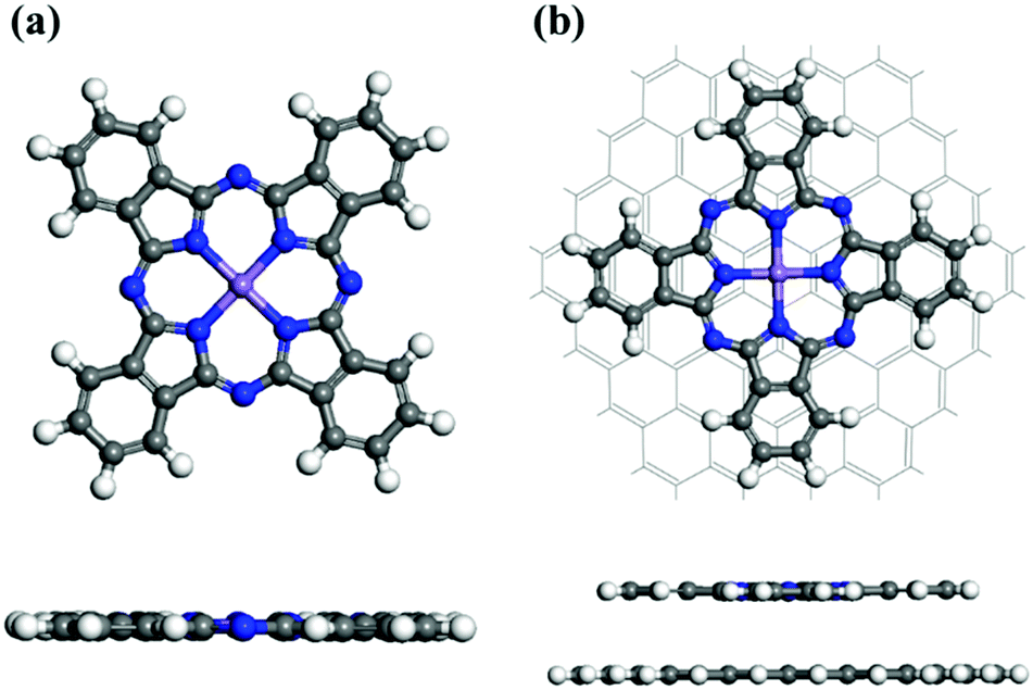
We first fully optimized the structures of pristine MnPc and MnPc/GQD using the DFT+U method.39Fig. 1(a) displays the geometry of fully-optimized MnPc, which reveals an almost planar macrocyclic configuration, in full agreement with a previous calculation,37 as summarized in Table 1. The average distance (1.955 Å) between the Mn atom and its surrounding N atoms (dMn–N) is overestimated (by less than 1%) compared to available experiment data,55,56 consistent with the previous computational study.37Fig. 1(b) shows a graphene quantum dot (GQD), which is also planar, functionalized with MnPc. The Mn–N bond length in MnPc/GQD is similar to that in the pristine MnPc, as summarized in Table 1.
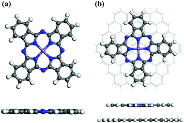 |
| | Fig. 1 Fully optimized geometries for (a) a MnPc monolayer and (b) MnPc/GQD. The central purple, blue, white, and gray spheres represent manganese, nitrogen, hydrogen, and carbon atoms, respectively. | |
Table 1 Calculated average distances (dMn–N) between Mn and its surrounding N atoms in the MnPc and MnPc/GQD systems
|
d
Mn–N (Å) |
| MnPc |
MnPc/GQD |
| Experimental |
Simulated |
This work |
This work |
| 1.937,55 1.93356 |
1.95537 |
1.955 |
1.950 |
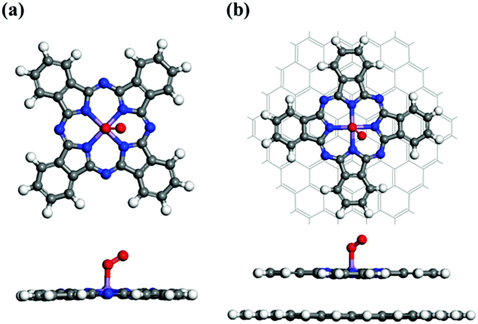
In general, the ORR mechanism begins with the chemisorption of O2 onto the catalyst surface.57 The calculated structures of O2-adsorbed MnPc and MnPc/GQD are displayed in Fig. 2(a) and (b), respectively. In order to obtain the most stable O2-adsorption configuration, an oxygen molecule was initially placed at the Mn sites of MnPc and MnPc/GQD in two different physisorption configurations, namely side-on and end-on. The oxygen molecules chemisorbed to the central Mn atoms of the MnPc and MnPc/GQD systems exhibited adsorption energies of −0.682 and −0.671 eV, respectively, based on the structures shown in Fig. 2; the adsorption energy (Ead) of the O2 molecule is determined by:58
| | | Ead = Esur_O2 − Esur−EO2 | (1) |
where
Esur_O2,
Esur, and
EO2 are the calculated total energies of the surface with the adsorbed O
2, the free surface, and the free O
2 molecule, respectively. A more negative
Ead indicates stronger O
2 adsorption. The calculated O
2-adsorption energies, along with O–O and Mn–O bond lengths, are listed in
Table 2.
 |
| | Fig. 2 Fully optimized geometries for O2 adsorbed on (a) the MnPc monolayer and (b) MnPc/GQD. The central purple, blue, white, gray, and red spheres represent manganese, nitrogen, hydrogen, carbon, and oxygen atoms, respectively. | |
Table 2 Calculated properties of the O2-adsorbed MnPc and MnPc/GQD systems
|
|
d
Mn–O (Å) |
d
O–O (Å) |
E
ad (eV) |
| MnPc |
1.888 |
1.300 |
−0.682 |
| MnPc/GQD |
1.845 |
1.286 |
−0.671 |
The higher kinetic ORR activity is related to the stronger adsorption of O2. The O2 adsorption energy on MnPc/GQD is −0.671 eV, which is less negative (more negative) than the adsorption energy of O2 on FePc/C (CoPc/C) catalyst by 0.489 eV (0.271 eV).31 The calculated O−O bond distances in MnPc and MnPc/GQD are longer than the bond length of the pristine O2 molecule (1.232 Å). These results show that these two systems are activated for participation in ORR reactions.25 The O−O and Mn–O distances in the O2-adsorbed MnPc/GQD are shorter than those of the isolated O2-MnPc. These distances were affected by the presence of the GQD matrix that influences the ORR performance of MnPc/GQD. Therefore, this computational method is viable for investigating the ORR mechanisms in the MnPc and MnPc/GQD systems.
Electronic properties
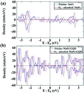
To understand the molecular-O2 activation mechanism in these two systems, and the effect of the GQD matrix on the MnPc monolayer in terms of their electronic properties, we analyzed the density of state (DOS), as shown in Fig. 3.
 |
| | Fig. 3 Density of state (DOS) of (a) MnPc and O2-adsorbed MnPc, and (b) MnPc/GQD and O2-adsorbed MnPc/GQD. | |
As displayed in Fig. 3, the DOS of both pristine MnPc and MnPc/GQD were shifted 0.371 eV and 0.217 eV, respectively, closer toward to their occupied energy levels following the adsorption of O2, with increased intensities around their Fermi levels, demonstrating that more electronic states exist at the highest-occupied energy level (the energy at the Fermi level was set to zero). This is possibly ascribable to the fact that electrons are injected from O2 toward the two aforementioned systems. Overall, these results also reveal that an O2 molecule is sufficiently activated on either MnPc or MnPc/GQD, facilitating its subsequent reduction. Fig. 3(a) shows the calculated HOMO–LUMO gap as 1.2 eV in pristine MnPc and this value is consistent with the results in previous studies.59,60 The HOMO–LUMO gap of MnPc in this study was lower than the gap of FePc, CoPc, NiPc, and CuPc in the other theoretical studies.38 In addition, Fig. 3(b) also shows that the intensity of the DOS near the Fermi level of the O2-adsorbed MnPc/GQD is higher than that of the isolated O2-adsorbed MnPc. In addition, more electrons are present around the Fermi level in the MnPc/GQD system than in pristine MnPc, inferring that the GQD-supported system would be more electronically conductive than the MnPc-monolayer system. Moreover, the calculated band gap value in MnPc/GQD system was 0.9 eV, which is smaller than the gap in MnPc system. Therefore, GQD appears to significantly improve the electronic properties of MnPc, inducing an increased number of transferred electrons to the oxygen atom, thereby enhancing ORR kinetics.61–63 To validate this hypothesis, we constructed thermodynamic free-energy diagrams to understand the catalytic properties of both systems.
Oxygen reduction reaction mechanisms
The differences in the free energies of the products and reactants of all ORR intermediates (ΔG)57 were calculated using eqn (2):where ΔG0, ΔGpH, and ΔGU are the Gibbs free-energy changes between the initial and final state under standard conditions (pH = 0, U = 0), the changes in free energy at a particular pH, and the changes in free energy at a particular electrode potential, respectively. In addition:| | ΔGpH = pH × kBT![[thin space (1/6-em)]](https://www.rsc.org/images/entities/char_2009.gif) ln10 ln10 | (3) |
where kB is the Boltzmann constant and T is the temperature. Here, the pH was chosen to be zero (i.e., acidic conditions), ΔGpH = 0 in our study, and:where e is the transferred charge and U is the potential energy of the electrode. Moreover, the standard hydrogen electrode (SHE) was considered to be the primary reference electrode, in which the H+-formation reaction (1/2H2 → H+ + e−) and the equilibrium process are under standard conditions of pH = 0, U = 0, P = 1 bar, and T = 298 K. Therefore, the free energy of this reaction (*AH → A + H+ + e−) is considered to be the energy for: *AH → A + 1/2H2.57,64 Under standard conditions, the Gibbs free energy (ΔG0) is given by:
Accordingly, the relative free energy is given by:
| | | ΔG(U,pH = 0,T) = ΔE + ΔZPE − TΔS − eU | (6) |
where Δ
E, ΔZPE, and Δ
S are the change in calculated total energy, change in zero point energy, and entropy change, respectively; values of ΔZPE for intermediate reactions were taken from Nørskov
et al.57 for all intermediate reactions, in which Δ
S are presented in a thermodynamic table
57,65 at 298 K. In addition, the Gibbs free energy of gaseous H
2O at zero potential was obtained at
T = 300 K and
P = 0.035 bar, along with the relative free energy of O
2 (4.92 eV) derived from the water-formation reaction: O
2 + 2H
2 = H
2O.
57,66
In a PEMFC operating environment, the entire ORR pathways can proceed through two possible mechanistic pathways, namely associative and dissociative pathways.67 The first reaction pathway considered involves the dissociative mechanism, in which the bond in the O2 chemisorbed on the surface is broken, with subsequent catalytic reaction steps occurring at each oxygen site. The second reaction pathway involves the associative mechanism. The O2 bond is not broken prior to hydrogenation in the associative mechanism, while the cleavage of this bond prior to hydrogenation is important to the dissociative mechanism,57 and is the major difference between these two mechanisms. Sun et al.68 investigated the oxygen-reduction performance of metallophthalocyanines and metalloporphyrins using Fe and Co as the transition metals, with the following associative mechanism:
| | | O2 → O2* (chemisorbed) | (7) |
| | | OOH* + H+ + e− → O* + H2O | (9) |
| | | O* + H2O + H+ + e− → OH* + H2O | (10) |
| | | OH* + H2O + H+ + e− → 2H2O | (11) |
This mechanism is the same as that for the FePc system identified by Wang et al.,69 and Mussell et al.70 concluded that this mechanism is the favored route for graphene-supported FePc. In addition, they also reported70 that the following mechanism is the most favored dissociative mechanism among the dissociative mechanisms investigated in their studies (dissociative pathway I):
| | | O*O* + H+ + e− → HO* + O* | (14) |
| | | HO* + O* + H+ + e− → HO* + HO* | (15) |
| | | HO* + HO* + H+ + e− → H2O + HO* | (16) |
| | | H2O + HO* + H+ + e− → 2H2O | (17) |
This route is widely accepted to be a reasonable dissociative mechanism operating in PEMFC-catalyst devices,71–73 for both PGM and non-PGM catalysts. Furthermore, another possible O2-dissociative pathway (pathway II),72 that include reactions (18) and (19), instead (15) and (16), were also investigated in our study:
| | | HO* + O* + H+ + e− → O* + H2O | (18) |
| | | H2O + O* + H+ + e− → H2O + OH* | (19) |
Consequently, we further studied the entire ORR route for each mechanism on the surfaces of the MnPc and MnPc/GQD systems. We examined the three reasonable routes described above; namely an associative mechanism and two dissociative mechanisms, while studying the catalytic properties of our systems.
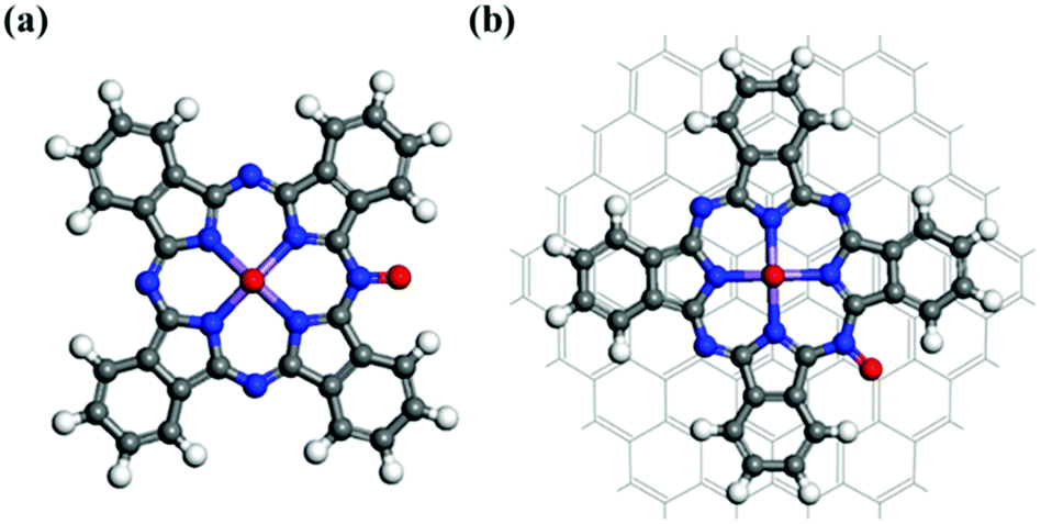
The O2-dissociated structures corresponding to reaction (13) in the dissociative mechanism are displayed in Fig. 4. Following O2 dissociation, one oxygen atom remains bonded to the Mn atom, while the other O is bonded to an edge N of the macrocycle. The distances between the O bonded to the Mn and Mn for the MnPc and MnPc/GQD systems were calculated to be 1.598 Å and 1.666 Å, respectively. This reaction was also calculated to be exothermic in each case; the free-energy changes for this reaction were determined to be −0.296 and −0.328 eV for the MnPc and MnPc/GQD systems, respectively.
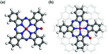 |
| | Fig. 4 Optimized structures of the O2-dissociated systems: (a) MnPc and (b) MnPc/GQD. | |
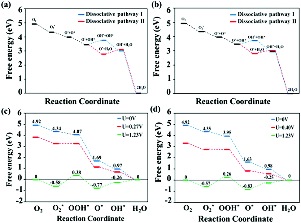
By performing thermodynamic calculations involving various intermediates, we evaluated the electrochemical ORR activities of the MnPc and MnPc/GQD systems through the use of free-energy diagrams, as shown in Fig. 5. The free energies of each intermediate in the reactions involved in the dissociative pathways involving MnPc and MnPc/GQD are shown in Fig. 5(a) and (b), respectively. In particular, step (15), which forms two separate OH groups in the first dissociative pathway, has a higher free energy than that of the alternative reaction, namely step (18) in the second dissociative route, by about 1.08 eV and 0.90 eV for MnPc and MnPc/GQD, respectively. Therefore, dissociative pathway II is energetically favored over dissociative pathway I in our systems. In addition, Fig. 5(a) and (c) show that the free energies of all steps in the associative mechanism are lower than those of the dissociative mechanism for the MnPc system. Therefore, the associative pathway is preferred over the dissociative counterpart on MnPc, which is consistent with data from other metallophthalocyanine systems, such as FePc,68 FePc/graphene,70 and various PGM-catalysts, especially for Pt(100) surfaces.74 Likewise, Fig. 5(b) and (d) also show that the associative pathway is preferred for the MnPc/GQD system. The free energies along the associative route are calculated by following each reaction step involving MnPc and MnPc/GQD, as shown in Fig. 5(c) and (d), respectively. According to these two figures, at the equilibrium potential, the reactions that form the O2* and O* groups are exothermic, while the remaining steps are endothermic. The rate-determining proton-transfer process for the ORR pathway on MnPc was found to involve the formation of OOH*, with a reaction barrier of 0.96 eV, as shown in Fig. 5(c). The same rate-determining step was found in other studies of transition-metal nitrogen-doped carbon75 and a model of graphene-supported FePc.70 However, this observation is different from that involving the oxygen-reduction reaction on a platinum monolayer,57,70,76 FeN4–graphene surface,77 or an iron phthalocyanine model,78 where OH* formation determines ORR activity. According to Fig. 5(c) and (d), the thermodynamic free-energy diagrams predict that MnPc/GQD is more active toward ORR than the isolated MnPc, clearly highlighting the effect of the GQD matrix on ORR activity from a thermodynamic perspective. This is also consistent with our electronic-property results. Moreover, the MnPc/GQD system exhibited the same thermodynamic rate-determining step as the MnPc system. Interestingly, the reaction involving MnPc/GQD is calculated to have a barrier of 0.83 eV, which is lower by 0.13 eV than the barrier in MnPc. In addition, the highest feasible operating potential was determined to be 0.27 V in the case of the MnPc monolayer, while this value was 0.40 V for MnPc/GQD. The lower reaction barrier and higher highest potential in MnPc/GQD make this system more attractive as an ORR candidate than the MnPc system. Hence, MnPc/GQD is a better ORR candidate than the pristine MnPc system. We conclude that GQD enhances the catalytic performance of metallophthalocyanine complexes.
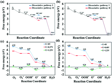 |
| | Fig. 5 ORR free-energy diagrams for the dissociative pathways (I and II) on (a) MnPc and (b) MnPc/GQD at zero potential (U = 0 V). Free-energy diagrams for the associative mechanisms at zero potential (U = 0 V, blue), equilibrium potential (U = 1.23 V, green), and the highest potential at which every reduction process is exothermic (red): (c) MnPc and (d) MnPc/GQD. | |
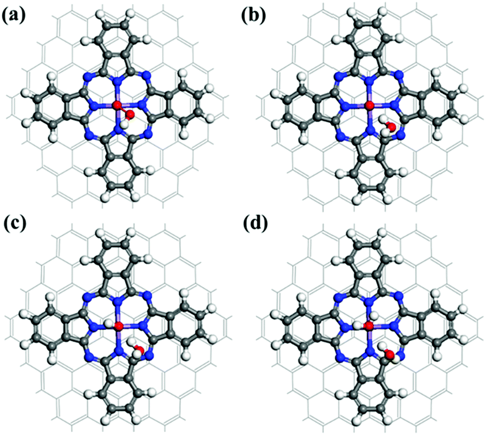
Fig. 6 displays the fully optimized geometries of the intermediate species involved in the ORR associative mechanism for the MnPc/GQD system. Associative electrocatalysis was achieved by the stepwise addition of a H+ followed by combination with an electron during the first hydrogenation step. An OOH* group was formed by the reaction of the O2 on MnPc/GQD with a hydrogen that was initially bonded to a nitrogen, as shown in Fig. 6(a). The reaction energy of this step was calculated to be −0.40 eV at zero potential, while it was 0.83 eV at equilibrium potential (U = 1.23 V). Fig. 6(b) displays the product of the next step; the second H is initially placed in the same way as observed during the initial hydrogenation reaction, and reacts with the OOH* group to form a H2O molecule with a 104.2° H–O–H angle. It was also noted that the remaining O atom on the MnPc/GQD was directly hydrogen bonded to this H2O molecule, at a distance of 1.750 Å. This means we would not be able to detect the formation of the H2O2 intermediate in our systems, which only appears in two-electron-reduction pathways in the associative route. Therefore, both MnPc and MnPc/GQD were found to only promote the four-electron pathway, which is the desired mechanism for PEMFCs. Hence, the 2e− reduction pathway was not included in our study. Fig. 6(c) displays the product from the next step in which a third hydrogen atom becomes bonded to the remaining O atom to form OH*. The second H2O molecule is formed through a fourth H+ that reacts with the bonded OH*, as described in reaction (11). As shown in Fig. 6(d), the O atom of the second H2O molecule is separated from the central Mn in MnPc/GQD by a distance of 2.461 Å; this distance was 2.449 Å for the MnPc-monolayer system. Moreover, hydrogen bonds are formed between the two water molecules created in each system. The distance between the O of the second H2O and the nearest H of the other water molecule was calculated to be 1.995 Å and 2.004 Å for the MnPc and MnPc/GQD systems, respectively.
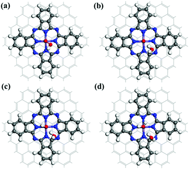 |
| | Fig. 6 Optimized structures of the intermediates formed in each step of the overall associative ORR sequence on MnPc/GQD: (a) OOH*, (b) O*, (c) OH*, and (d) H2O. | |
Conclusions
We used first-principles calculations to study ORR processes that occur on MnPc and MnPc/GQD systems in terms of their electrochemical activities and electronic properties. Our calculations show that the MnPc single-atom catalyst facilitates the four-electron oxygen-reduction mechanism, which is suitable for efficient non-precious-metal electrocatalysts in PEMFCs. Furthermore, the electrocatalytic ORR cycle in each system can occur through two possible mechanisms; however the associative pathway is preferred for MnPc and MnPc/GQD. The rate-limiting step was found to involve the formation of OOH*, with reaction barriers of 0.96 eV and 0.83 eV for the MnPc-monolayer and MnPc/GQD systems, respectively, at the maximum fuel-cell operating potential (U = 1.23 V). Moreover, the GQD significantly enhances the electronic properties and ORR activity of MnPc, increasing the highest potential from 0.27 V for the isolated MnPc to 0.4 V for MnPc/GQD. Hence, GQD is a strong C-support-matrix candidate for high-efficiency catalysts and can be potentially used in PEMFCs.
Conflicts of interest
There are no conflicts to declare.
Acknowledgements
This research was supported by the National Research Foundation of Korea (NRF) funded by the Ministry of Science, ICT & Future Planning (No. NRF-2015M1A2A2057129 and NRF-2016M1A2A2937151). This study was supported by the Basic Science Research Program through the National Research Foundation of Korea (NRF) funded by the Ministry of Science, ICT and Future Planning (No. NRF-2017R1E1A1A01074266 and NRF-2017R1C1B5015469).
References
- R. Bashyam and P. Zelenay, Nature, 2006, 443, 63–66 CrossRef CAS PubMed.
- M. Jacobson, W. Colella and D. Golden, Science, 2005, 308, 1901–1905 CrossRef CAS PubMed.
- M. G. Schultz, T. Diehl, G. P. Brasseur and W. Zittel, Science, 2003, 302, 624–627 CrossRef CAS PubMed.
- Y. Wang, K. S. Chen, J. Mishler, S. C. Cho and X. C. Adroher, Appl. Energy, 2011, 88, 981–1007 CrossRef CAS.
-
A. Appleby and F. Foulkes, Fuel Cell Handbook, Krieger Publishing Company, Melborne, FL, 1993 Search PubMed.
- J. Zhang, Z. Xie, J. Zhang, Y. Tang, C. Song, T. Navessin, Z. Shi, D. Song, H. Wang and D. P. Wilkinson, J. Power Sources, 2006, 160, 872–891 CrossRef CAS.
- C. Song, Catal. Today, 2002, 77, 17–49 CrossRef CAS.
- C. R. Rao and D. Trivedi, Coord. Chem. Rev., 2005, 249, 613–631 CrossRef CAS.
- S. M. Lloyd, L. B. Lave and H. S. Matthews, Environ. Sci. Technol., 2005, 39, 1384–1392 CrossRef CAS PubMed.
- E. L. Miller, D. Papageorgopoulos, N. Stetson, K. Randolph, D. Peterson, K. Cierpik-Gold, A. Wilson, V. Trejos, J. C. Gomez and N. Rustagi, MRS Adv., 2016, 1, 2839–2855 CrossRef CAS.
- H. Gasteiger and S. Yan, J. Power Sources, 2004, 127, 162–171 CrossRef CAS.
-
PEM fuel cell electrocatalysts and catalyst layers: fundamentals and applications, ed. J. Zhang, Springer-Verlag, London, 2008 Search PubMed.
- D. J. Berger, Science, 1999, 286, 49 CrossRef CAS.
- T. A. Semelsberger and R. L. Borup, Int. J. Hydrogen Energy, 2005, 30, 425–435 CrossRef CAS.
- J. Xie, D. L. Wood, K. L. More, P. Atanassov and R. L. Borup, J. Electrochem. Soc., 2005, 152, A1011–A1020 CrossRef.
- J. Liu, X. F. Fan, C. Q. Sun and W. G. Zhu, Appl. Surf. Sci., 2018, 441, 23–28 CrossRef CAS.
- D. Liu, Z. Y. Gao, X. C. Wang, J. Zeng and Y. M. Li, Appl. Surf. Sci., 2017, 426, 194–205 CrossRef CAS.
- E. Proietti, F. Jaouen, M. Lefèvre, N. Larouche, J. Tian, J. Herranz and J.-P. Dodelet, Nat. Commun., 2011, 2, 416 CrossRef PubMed.
- D. Banham and S. Y. Ye, ACS Energy Lett., 2017, 2, 629–638 CrossRef CAS.
- J. Shui, C. Chen, L. Grabstanowicz, D. Zhao and D.-J. Liu, Proc. Natl. Acad. Sci. U. S. A., 2015, 112, 10629–10634 CrossRef CAS PubMed.
- S. Holdcroft, Chem. Mater., 2013, 26, 381–393 CrossRef.
- H. A. Gasteiger, S. S. Kocha, B. Sompalli and F. T. Wagner, Appl. Catal., B, 2005, 56, 9–35 CrossRef CAS.
- B. Wang, J. Power Sources, 2005, 152, 1–15 CrossRef CAS.
- R. Othman, A. L. Dicks and Z. Zhu, Int. J. Hydrogen Energy, 2012, 37, 357–372 CrossRef CAS.
- R. Jasinski, Nature, 1964, 201, 1212–1213 CrossRef CAS.
-
K. Liu, Y. Lei, R. Chen and G. Wang, Electrochemistry of N4 Macrocyclic Metal Complexes, Springer, 2016, pp. 1–39 Search PubMed.
- J. E. Lyons and P. E. Ellis, Appl. Catal., A, 1992, 84, L1–L6 CrossRef CAS.
- F. Ghani, J. Kristen and H. Riegler, J. Chem. Eng. Data, 2012, 57, 439–449 CrossRef CAS.
-
H. Meier, U. Tschirwitz, E. Zimmerhackl and W. Albrecht, Investigation of acid-resistant electrocatalysts for fuel cells, West German Report, Bamberg, Germany, 1975 Search PubMed.
- A. B. Sorokin, Chem. Rev., 2013, 113, 8152–8191 CrossRef CAS PubMed.
- R. Chen, H. Li, D. Chu and G. Wang, J. Phys. Chem. C, 2009, 113, 20689–20697 CrossRef CAS.
- C. Broicher, J. Artz, S. Palkovits, H. Antoni, M. Drögeler, D. M. Morales, C. Stampfer and R. Palkovits, Catal. Sci. Technol., 2018, 8, 1517–1521 RSC.
- Z. Zhang, J. Zhang, N. Chen and L. Qu, Energy Environ. Sci., 2012, 5, 8869–8890 RSC.
- K. H. Koh, S. H. Noh, T.-H. Kim, W. J. Lee, S.-C. Yi and T. H. Han, RSC Adv., 2017, 7, 26113–26119 RSC.
- K. Kaare, I. Kruusenberg, M. Merisalu, L. Matisen, V. Sammelselg and K. Tammeveski, J. Solid State Electrochem., 2016, 20, 921–929 CrossRef CAS.
- Z. Zhang, S. Yang, M. Dou, H. Liu, L. Gu and F. Wang, RSC Adv., 2016, 6, 67049–67056 RSC.
- W. Orellana, Chem. Phys. Lett., 2012, 541, 81–84 CrossRef CAS.
- I. E. Brumboiu, S. Haldar, J. Lüder, O. Eriksson, H. C. Herper, B. Brena and B. Sanyal, J. Chem. Theory Comput., 2016, 12, 1772–1785 CrossRef CAS PubMed.
- S. Dudarev, G. Botton, S. Savrasov, C. Humphreys and A. Sutton, Phys. Rev. B: Condens. Matter Mater. Phys., 1998, 57, 1505 CrossRef CAS.
- G. Kresse and J. Furthmüller, Phys. Rev. B: Condens. Matter Mater. Phys., 1996, 54, 11169 CrossRef CAS.
- G. Kresse and J. Furthmuller, Comput. Mater. Sci., 1996, 6, 15–50 CrossRef CAS.
- S. Grimme, J. Comput. Chem., 2006, 27, 1787–1799 CrossRef CAS PubMed.
- G. H. A. Jain, S. P. Ong, C. J. Moore, C. C. Fischer, K. A. Persson and G. Ceder, Phys. Rev. B: Condens. Matter Mater. Phys., 2011, 84, 045115 CrossRef.
- A. V. Lebedev, I. V. Lebedeva, A. A. Knizhnik and A. M. Popov, RSC Adv., 2016, 6, 33945 RSC.
- S. Miranda-Rojas, P. Sierra-Rosales, A. Munoz-Castro, R. Arratia-Perez, J. H. Zagal and F. Mendizabal, Phys. Chem. Chem. Phys., 2016, 18, 29516–29525 RSC.
- J. P. Perdew, K. Burke and M. Ernzerhof, Phys. Rev. Lett., 1996, 77, 3865 CrossRef CAS PubMed.
- S. K. Park, S. H. Kwon, S. G. Lee, M. S. Choi, D. H. Suh, P. Nakhanivej, H. Lee and H. S. Park, ACS Energy Lett., 2018, 3, 724–732 CrossRef CAS.
- T. V. Tam, S. G. Kang, K. F. Babu, E.-S. Oh, S. G. Lee and W. M. Choi, J. Mater. Chem. A, 2017, 5, 10537–10543 RSC.
- G. F. Brunello, J. H. Lee, S. G. Lee, J. I. Choi, D. Harvey and S. S. Jang, RSC Adv., 2016, 6, 69670–69676 RSC.
- H. W. Lee, H. S. Moon, J. Hur, I. T. Kim, M. S. Park, J. M. Yun, K. H. Kim and S. G. Lee, Carbon, 2017, 119, 492–501 CrossRef CAS.
- H. S. Moon, J. M. Yun, K. H. Kim, S. S. Jang and S. G. Lee, RSC Adv., 2016, 6, 39587–39594 RSC.
- J. H. Lee, S. G. Kang, H. S. Moon, H. Park, I. T. Kim and S. G. Lee, Appl. Surf. Sci., 2015, 351, 193–202 CrossRef CAS.
- G. Makov and M. Payne, Phys. Rev. B: Condens. Matter Mater. Phys., 1995, 51, 4014 CrossRef CAS.
- H. J. Monkhorst and J. D. Pack, Phys. Rev. B: Condens. Matter Mater. Phys., 1976, 13, 5188 CrossRef.
- J. F. Kirner, W. Dow and W. R. Scheidt, Inorg. Chem., 1976, 15, 1685–1690 CrossRef CAS.
- R. Mason, G. A. Williams and P. E. Fielding, J. Chem. Soc., Dalton Trans., 1979, 676–683 RSC.
- J. K. Nørskov, J. Rossmeisl, A. Logadottir, L. Lindqvist, J. R. Kitchin, T. Bligaard and H. Jonsson, J. Phys. Chem. B, 2004, 108, 17886–17892 CrossRef.
-
D. S. Sholl and J. A. Steckel, Density Functional Theory: A Practical Introduction, John Wiley & Sons, Inc., Hoboken, New Jersey, 2009, pp. 179–192 Search PubMed.
- F. Haidu, A. Fechner, G. Salvan, O. Gordan, M. Fronk, D. Lehmann, B. Mahns, M. Knupfer and D. Zahn, AIP Adv., 2013, 3, 062124 CrossRef.
- D. Stradi, C. Díaz, F. Martín and M. Alcamí, Theor. Chem. Acc., 2011, 128, 497–503 Search PubMed.
- J. Zagal, M. Paez, A. Tanaka, J. dos Santos Jr. and C. Linkous, J. Electroanal. Chem., 1992, 339, 13–30 CrossRef CAS.
- H. Kim, K. Lee, S. I. Woo and Y. Jung, Phys. Chem. Chem. Phys., 2011, 13, 17505–17510 RSC.
- H. Tominaga, W. Ikeda and M. Nagai, Phys. Chem. Chem. Phys., 2011, 13, 2659–2662 RSC.
- G. Karlberg, J. Rossmeisl and J. K. Nørskov, Phys. Chem. Chem. Phys., 2007, 9, 5158–5161 RSC.
-
P. Atkins and J. De Paula, Physical Chemistry: Thermodynamics, structure, and change, Oxford University Press, Oxford, UK, 8th edn, 2006 Search PubMed.
- X. Nie, W. Luo, M. J. Janik and A. Asthagiri, J. Catal., 2014, 312, 108–122 CrossRef CAS.
- I. E. Stephens, A. S. Bondarenko, U. Grønbjerg, J. Rossmeisl and I. Chorkendorff, Energy Environ. Sci., 2012, 5, 6744–6762 RSC.
- S. Sun, N. Jiang and D. Xia, J. Phys. Chem. C, 2011, 115, 9511–9517 CrossRef CAS.
- Y. Wang, H. Yuan, Y. Li and Z. Chen, Nanoscale, 2015, 7, 11633–11641 RSC.
- S. Mussell and P. Choudhury, J. Phys. Chem. C, 2016, 120, 5384–5391 CrossRef CAS.
- F. Studt, Catal. Lett., 2013, 143, 58–60 CrossRef CAS.
- Y. Okamoto, Appl. Surf. Sci., 2009, 256, 335–341 CrossRef CAS.
- H. Li, Z. Xu, K. Li, X. Hou, G. Cao, Q. Zhang and Z. Cao, J. Mater. Chem., 2011, 21, 1181–1186 RSC.
- S. H. Noh, D. H. Kwak, M. H. Seo, T. Ohsaka and B. Han, Electrochim. Acta, 2014, 140, 225–231 CrossRef CAS.
- J. Zhang, Z. Wang and Z. Zhu, J. Power Sources, 2014, 255, 65–69 CrossRef CAS.
- B. Han, V. Viswanathan and H. Pitsch, J. Phys. Chem. C, 2012, 116, 6174–6183 CrossRef CAS.
- J. Zhang, Z. Wang, Z. Zhu and Q. Wang, J. Electrochem. Soc., 2015, 162, F796–F801 CrossRef CAS.
- M. H. Seo, D. Higgins, G. Jiang, S. M. Choi, B. Han and Z. Chen, J. Mater. Chem. A, 2014, 2, 19707–19716 RSC.
|
| This journal is © The Royal Society of Chemistry and the Centre National de la Recherche Scientifique 2019 |
Click here to see how this site uses Cookies. View our privacy policy here. 
 a,
Hee-Tak
Kim
a,
Hee-Tak
Kim