
High efficiency tandem polymer solar cells with MoO3/Ni/ZnO:PEOz hybrid interconnection layers†
Jooyeok
Seo
a,
Yejin
Moon
a,
Sooyong
Lee
a,
Chulyeon
Lee
a,
Dohan
Kim
a,
Hwajeong
Kim
*ab and
Youngkyoo
Kim
 *a
*a
aOrganic Nanoelectronics Laboratory and KNU Institute for Nanophotonics Applications (KINPA), Department of Chemical Engineering, School of Applied Chemical Engineering, Kyungpook National University, Daegu 41566, Republic of Korea. E-mail: ykimm@knu.ac.kr
bPriority Research Center, Research Institute of Environmental Science & Technology, Kyungpook National University, Daegu 41566, Republic of Korea. E-mail: khj217@knu.ac.kr
First published on 15th May 2019
Abstract
Here we report high efficiency tandem polymer solar cells with hybrid electron-collecting buffer layers (ECBLs) for interconnection between front and rear cells. The hybrid ECBLs, poly(2-ethyl-2-oxazoline) (PEOz)-embedded ZnO (ZnO:PEOz), were prepared via low-temperature sol–gel processes on nickel (Ni) interlayers that are desposited on molybdenum oxide (MoO3) buffer layers. The Ni interlayers were employed to act as an electrical conductor and a protection layer for the MoO3 layers against the attack of solvent during spin-coating of the ZnO:PEOz layers. A new conjugated polymer was synthesized and mixed with soluble fullerenes to make polymer:fullerene bulk heterojunction (BHJ) layers for the front cells, while polymer:nonfullerene BHJ layers were employed for the rear cells. The thickness of the Ni interlayers was varied up to 10 nm in order to investigate the trade-off between optical transmittance and electrical conductivity in the tandem cells. The results showed that the ZnO:PEOz ECBLs delivered a nanocratered surface in the tandem polymer solar cells and the device performaces were greatly affected by the Ni thickness. The optimized tandem polymer solar cells exhibited a power conversion efficiency of 14.22% at the Ni thickness of 6 nm.
New conceptsInterconnection layers in tandem polymer solar cells play a crucial role in linking between front and rear cells, because they have to secure efficient charge transport between them. Therefore, the interconnection layers should be safely prepared without any damage to the active layers of the front (bottom) cells, while they should be also stable against solvent attacks during wet-coating of the next active layers for the rear (top) cells. Although wet-processed conducting polymer layers such as PEDOT:PSS were used as a p-type (hole-collecting) interconnection component, achieving good quality nanolayers is still very tricky because of strong hydrophilic characteristics compared to the hydrophobic nature of the active layers. As an n-type (electron-collecting) interconnection component, zinc oxide (ZnO) nanoparticles have been used but the resulting nanoparticle layers are vulnerable to poor uniformity with large-scale defects. Molybdenum oxide (MoO3) has also been applied as a p-type interconnection component but their layers are unstable to the attack of solvents during subsequent wet-coating steps for top cells. Here we demonstrate that 14.22% tandem polymer solar cells can be successfully fabricated with the interconnection layers composed of MoO3, nickel (Ni), and ZnO:poly(2-ethyl-2-oxazoline) (PEOz) hybrids prepared at a low temperature (140 °C). |
Introduction
Polymer solar cells, which are based on bulk heterojunction (BHJ) nanostructures of conjugated polymers and/or small molecules, have been spotlighted for the last two decades because of their potential for paper-like ultrathin, lightweight and flexible solar modules.1–3 The early breakthroughs have shown that polymer solar cells can be fabricated on large-area plastic film substrates by employing wet-coating and roll-to-roll coating methods at low-temperatures.4–9 However, the power conversion efficiency (PCE) of the polymer solar cells is still behind those of crystalline silicon (ca. 26.7%) and perovskite (ca. 23.3%) solar cells, even though ca. 12–14% PCE has been recently reported for polymer solar cells with single BHJ layers.10,11The low PCE of polymer solar cells can be ascribed to the low carrier mobility of organic materials owing to the relatively lower crystallinity compared to that of crystalline silicon and perovskite materials.12–16 As a consequence, the thickness of polymeric BHJ layers is limited to typically less than 200 nm and cannot be increased up to sub-micrometer ranges which are easy for crystalline silicon and perovskite materials. In this regard, tandem cell approaches can make sense because the thin polymeric BHJ layers are confined to each sub-cell so that the thickness limitation can be resolved.17–22 In particular, the tandem cell structures can benefit effective exploitation of light absorption by adjusting the BHJ layers with different optical absorption ranges for front and rear cells.17,18,20 Although ca. 17% PCE was recently achieved for tandem polymer solar cells by stacking two sub-cells with different optical absorption profiles,23 it is considered that there are still a limited number of successful reports on tandem polymer solar cells.
The reason can be attributed to practical difficulties in making interconnection (charge transport junction) buffer layers between front and rear cells, even though several methods have been reported so far.24,25 In the case of inverted-type polymer solar cells, the interconnection buffer layers can be prepared by coating p-type sub-buffer layers first on the BHJ layer of the front cells and then n-type sub-buffer layers subsequently for contacting the rear cells. As the first p-type sub-buffer layer, poly(3,4-ethylenedioxythiophene):poly(styrenesulfonate) (PEDOT:PSS) was employed but it was very tricky to obtain well-made layers because of strong hydrophilic characteristics (high polarity as aqueous solutions) compared to the hydrophobic nature of the BHJ layers. As the n-type sub-buffer layers, zinc oxide (ZnO) nanoparticle solutions have been used but uniform and perfect coating issues still remain in the presence of high electrical resistances.26 Here, a keen interest can be paid to molybdenum(VI) oxide (MoO3) because it plays a crucial role as a p-type buffer layer in high efficiency inverted-type polymer solar cells (single-stack).27,28 However, the MoO3 layers are vulnerable to the attack of solvents during the next wet-coating processes for rear cells. In this regard, silver (Ag) was introduced on the MoO3 layers but its soft nature is considered to be still a hurdle for resolving the issues perfectly.29,30 In addition, the work function of Ag (ca. 4.7 eV) is lower than the valence band of MoO3 (ca. 5.3 eV) leading to the generation of an energy barrier (ca. 0.6 eV).31–34 Therefore, various new approaches for stable and efficient interconnection buffer layers are still strongly required to advance the performance and reproducibility of tandem polymer solar cells.
In this work, we demonstrate that high efficiency tandem polymer solar cells with good reproducibilty can be realized by placing hybrid electron-collecting buffer layers (ECBLs) on the nickel (Ni) interlayers that are deposited on the MoO3 layers. The semi-transparent Ni interlayers were chosen because they have a well-matched valence band energy level (5.19 eV) with the MoO3 layers (theoretical energy barrier = 0.11 eV only) and are capable of giving good electrical conduction and protecting the underneath MoO3 layers upon the next wet-coating processes when it comes to the dense (hard) nature of Ni metal.35,36 The hybrid ECBLs were prepared via sol–gel processes of the precursor mixtures of poly(2-ethyl-2-oxazoline) (PEOz) and ZnO (ZnO:PEOz) at low temperatures because of their particular nanocrater morphology leading to high efficieny.37,38 The results showed that the thickness of the Ni interlayers strongly influenced the performance of the tandem polymer solar cells. The best tandem polymer solar cells delivered 14.22% PCE, which is one of the most competitive reported to date in the field of tandem polymer solar cells.
Results and discussion
As shown in Fig. 1a, the tandem polymer solar cells were fabricated by stacking polymer:fullerene (front) and polymer:nonfullerene (rear) cells in the presence of the MoO3/Ni/ZnO:PEOz interconnection layers between these two cells. For the polymer:fullerene front cells, poly[{5,5,11,11-tetrakis(5-(2-ethylhexyl)thiophene-2-yl)-dithieno[2,3-d:2′,3′-d′]-s-indaceno[1,2-b:5,6-b′]dithiophene-3,9-diyl}-co-{(2,1,3-benzothiadiazole)-4,7-diyl}] (PIDTT-BT) was newly synthesized as depicted in Fig. 1b (see Fig. S1, ESI†). The synthesized PIDTT-BT polymer was mixed with [6,6]-phenyl-C71-butyric acid methyl ester (PC71BM) for the preparation of the BHJ (PIDTT-BT:PC71BM) layers (see Fig. 1c), while the BHJ layers of polymer:nonfullerene rear cells were made by blending poly[(2,6-(4,8-bis(5-(2-ethylhexyl)thiophen-2-yl)-benzo[1,2-b:4,5-b′]dithiophene))-alt-(5,5-(1′,3′-di-2-thienyl-5′,7′-bis(2-ethylhexyl)benzo[1′,2′-c:4′,5′-c′]dithiophene-4,8-dione))] (PBDB-T) and 3,9-bis(6-methyl-2-methylene-(3-(1,1-dicyanomethylene)-indanone))-5,5,11,11-tetrakis(4-hexylphenyl)-dithieno[2,3-d:2′,3′-d′]-s-indaceno[1,2-b:5,6-b′]dithiophene (IT-M) (see Fig. 1c). | ||
| Fig. 1 Device structure, materials, absorption spectra, and energy band diagram. (a) Illustration for the device structure for tandem polymer solar cells with the interconnection layer (MoO3/Ni/ZnO:PEOz). (b) Scheme for the synthesis of PIDTT-BT via a Stille coupling reaction between 2Sn-IDTT and 2Br-BT. (c) Chemical strctures for PBDB-T, IT-M, PC71BM and PEOz. (d) Optical absorption spectra for PIDTT-BT:PC71BM (1), PBDB-T:IT-M (2), and PIDTT-BT:PC71BM/MoO3/Ni(6 nm)/ZnO:PEOz/PBDB-T:IT-M (3). (e) Flat energy band diagram for the present tandem polymer solar cell. | ||
The thickness of the Ni interlayers, which were deposited on the MoO3 layers in the PIDTT-BT:PC71BM front cells, was varied up to 10 nm in order to investigate an optimum condition in regard to trade-off between electrical resistance (conductivity) and optical transparency. The ZnO:PEOz sub-buffer layers were spin-coated on the Ni/MoO3 layers, followed by thermal annealing at 140 °C for 60 min. As compared in Fig. 1d, the PIDTT-BT:PC71BM layers have an advantage in absorbing at a shorter wavelength range but the PBDB-T:IT-M layers are capable of absorbing photons at longer wavelengths. Consequently, the present tandem structures can possess a broadband light absorption capability between 300 nm and 900 nm (note that the optical absorption between 800 nm and 900 nm can be attributed to the influence of Ni interlayers). As illustrated in the flat energy band diagram (Fig. 1e), the Ni interlayers play a core role in connection between the front and rear cells when it comes to the Ni work function of ca. 5.19 eV, which well-matches the highest occupied molecular orbital (HOMO) energy of the MoO3 layers so as to enable hole charges to effectively transport toward the rear cells from the front cells with miminal losses. To understand the performance of tandem polymer solar cells, both individual front and rear cells were investigated with the device geometry as illustrated in Fig. 2a. As shown in current density–voltage (J–V) curves in Fig. 2b, the front cell (PIDTT-BT:PC71BM) exhibited relatively lower performance than the rear cell (PBDB-T:IT-M). Although the PCE of the front cells was only 6.13%, their open circuit voltage (VOC) reached ca. 0.89 V which is pretty high, close to that of the rear cells (VOC = 0.93 V). In addition, both devices delivered high short circuit current density (JSC) (14.73 and 17.29 mA cm−2 for front and rear cells, respectively) (see Table 1). The external quantum efficiency (EQE) spectra indicate that the front cells can absorb photons in the relatively shorter wavelengths but the rear cells have a benefit in asborbing photons in the longer wavelengths (>650 nm) (see Fig. 2c). This decoupled photon absorption range, even though small, is considered to contribute to the additional harvesting of incident light. In addition, the still high EQE values (>50%) even at the shorter wavengths for the rear cells will be of benefit because the rear cells can effectively generate electrons by absorbing these photons passing through the front cells.
 | ||
| Fig. 2 Structure and performance of individual solar cells. (a) Device structure for individual solar cells which correspond to the front (PIDTT-BT:PC71BM) and rear (PBDB-T:IT-M) cells in the tandem polymer solar cells. (b) Light (air mass 1.5G, 100 mW cm−2) J–V curves for the individual solar cells. (c) EQE spectra of the individual solar cells: JM and JC represent the measured short circuit density (mA cm−2) from the J–V curves and the calculated short current density integrated from the EQE spectra, respectively. | ||
| Parameters | PIDTT-BT:PC71BM solar cells (for front cell) | PBDB-T:IT-M solar cells (for rear cell) |
|---|---|---|
| V OC (V) | 0.89 (±0.01) | 0.93 (±0.01) |
| J SC (mA cm−2) | 14.73 (±0.09) | 17.29 (±0.26) |
| FF (%) | 47.32 (±1.07) | 73.19 (±0.39) |
| PCE (%) | 6.13 (±0.29) | 11.83 (±0.18) |
| R S (kΩ cm2) | 0.18 (±0.01) | 0.07 (±0.01) |
| R SH (kΩ cm2) | 0.89 (±0.01) | 0.93 (±0.01) |
Based on the informaiton of the invidual cells, the performance of tandem polymer solar cells was investigated according to the thickness of the Ni interlayers (tNi). As shown in the light J–V curves (Fig. 3a), the VOC of tandem polymer solar cells reached 1.56 V at the Ni thickness of 2 nm (see Table 2 and Table S1, ESI†). Note that reasonable performances could not be obtained when no Ni layer was inserted (see Fig. S2, ESI†). Similarly, both JSC and fill factor (FF) were very low so that the resulting PCE was only 3.64% (average) in the case of 2 nm-thick Ni interlayers. As the Ni thickness increased, the JSC of the devices was noticeably improved and reached 12.86 mA cm−2 (average) at the Ni thickness of 6 nm (see Fig. 3b for the simulated EQE spectral shape of tandem polymer solar cells). It is noted that the actual EQE spectrum of tandem cells could not be properly measured owing to the insufficient penetration of monochromatic light into the thick active layers (total 180 nm) as given in Fig. S3, ESI.†![[thin space (1/6-em)]](https://www.rsc.org/images/entities/char_2009.gif) 39 However, further increasing the Ni thickness caused JSC to decrease gradually (see Fig. 3c), which can be attributed to the reduced optical transparency of the Ni interlayers leading to considerable blocking of light passing from the front cells toward the rear cells (Fig. 3d, e and Fig. S4, ESI†).
39 However, further increasing the Ni thickness caused JSC to decrease gradually (see Fig. 3c), which can be attributed to the reduced optical transparency of the Ni interlayers leading to considerable blocking of light passing from the front cells toward the rear cells (Fig. 3d, e and Fig. S4, ESI†).
 | ||
| Fig. 3 Performance of tandem polymer solar cells and optical transmittance of Ni interlayers. (a) Light (air mass 1.5G, 100 mW cm−2) J–V curves for the tandem polymer solar cells according to the Ni thickness (tNi). (b) Normalized EQE (simulated) spectrum for the tandem polymer solar cell compared to those of individual front and rear cells (data from Fig. 2c). (c) JSC, VOC, FF and PCE as a function of the Ni thickness. Note that all data were extracted from the light J–V curves for more than 40 devices and then the average values are displayed with error bars for standard deviations. (d) Optical transmittance spectra for the Ni layers, which were coated on quartz substrates, according to the Ni thickness (tNi). (e) Optical transmittance of the Ni layers according to their thickness for three representative wavelengths. | ||
| Parameters | t Ni (nm) | |||
|---|---|---|---|---|
| 0 | 2 | 6 | 10 | |
| V OC (V) | 0.60 (±0.02) | 1.56 (±0.01) | 1.61 (±0.01) | 1.10 (±0.02) |
| J SC (mA cm−2) | 7.088 (±0.85) | 5.514 (±0.26) | 12.86 (±0.18) | 9.92 (±0.52) |
| FF (%) | 29.9 (±1.20) | 42.3 (±0.40) | 68.3 (±1.20) | 69.5 (±1.80) |
| PCE (%) | 1.257 (±0.23) | 3.640 (±0.18) | 14.05 (±0.17) | 7.59 (±0.22) |
Interestingly, the VOC of tandem cells marginally increased from 1.56 V (tNi = 2 nm) to 1.61 V (tNi = 6 nm) but it suddenly dropped down to 1.1 V at tNi = 10 nm, which can be also explained by the weakened photovoltage effect caused by the reduced optical transparency of the Ni interlayers. It is also noted that the VOC of the best tandem polymer solar cells (tNi = 6 nm) could reach 1.61 V even though inevitably a small amount of VOC loss (ca. 0.21 V) was found compared to the VOC sum (ca. 1.82 V) of the individual front and rear cells (see Fig. S5a, ESI†).40 In particular, the FF of the devices also noticeably increased from 42.3% (tNi = 2 nm) to 73.1% (tNi = 8 nm). The similar quick jumps in both JSC and FF can be attributed to the increased electrical conductivity as the Ni interlayers became thicker (see the significantly reduced series resistances from 0.64 kΩ cm2 at tNi = 2 nm and 0.14 kΩ cm2 at tNi = 6 nm in Table S1, ESI†). As a result, the best average PCE of 14.05% (the highest PCE = 14.22%) was achieved at tNi = 6 nm due to the combination of the resulting JSC, VOC, and FF. Here it is worthy to note that the PCE reached 10.03% only for the tandem polymer solar cells with the neat ZnO ECBLs without PEOz, which were coated on the 6 nm-thick Ni layers and thermally annealed at 140 °C (see Fig. S6, ESI†). As compared with previous reports in Table S2 (ESI†), the present tandem polymer solar cells delivered the highest PCE amongst those with the MoO3/metal/ZnO derivative structures. Here it is noted that the present tandem polymer solar cells were measured by covering a shadow mask on top of the glass side of the devices for preventing a waveguide effect and by isolating active zones electrically for avoiding charges transported from neighbouring regions adjacent to the active zones (see the large influence of extra charges on the JSC value in Fig. S7, ESI†).
The excellent performances of tandem polymer solar cells can be attributed to the successful stacking of the front and rear cells by introducing the present buffer layer structure for efficient charge transport between the two sub-cells. As shown from the atomic force microscope (AFM) images in Fig. 4, each layer was well-formed step by step up to the Ni interlayers. The root-mean-square roughness (Rg) was well-controlled even after depositing the Ni interlayers (tNi = 6 nm). Interestingly, the Rg value largely increased because of the nanocrater morphology formed on the ZnO:PEOz sub-buffer layers (see Fig. 4d), which is evidence of well-made hybrid (ZnO:PEOz) layers for the increased interfacial contact area and adhesion (via a mechanical interlocking geometry) leading to enhanced charge collection characteristics.41–43 Finally, the next BHJ (PBDB-T:IT-M) layers with noticeably reduced Rg values could be safely coated on the well-established ZnO:PEOz sub-buffer layers (see Fig. 4e). The well-formed multi-interfaces by introducing the present MoO3/Ni/ZnO:PEOz interconnection layer structures are confirmed by the scanning transmission electron microscope (STEM) images on the cross-sectional parts of the tandem polymer solar cells (see Fig. S8, ESI†). This result supports that the Ni interlayers were almost perfectly maintained even after wet-coating and thermal annealing of the ZnO:PEOz layers in the present tandem solar cells. Note that the wavy top part of the ZnO:PEOz layers can be attributed to the nanocraters.
 | ||
| Fig. 4 2D (top) and 3D (bottom) height-mode AFM images for each layer in the present tandem polymer solar cells: (a) ITO/ZnO/PIDTT-BT:PC71BM, (b) ITO/ZnO/PIDTT-BT:PC71BM/MoO3, (c) ITO/ZnO/PIDTT-BT:PC71BM/MoO3/Ni(6 nm), (d) ITO/ZnO/PIDTT-BT:PC71BM/MoO3/Ni(6 nm)/ZnO:PEOz, and (e) ITO/ZnO/PIDTT-BT:PC71BM/MoO3/Ni(6 nm)/ZnO:PEOz/PBDB-T:IT-M. Note that the root-mean-square roughness (Rg) was obtained from the full scan size (2 μm × 2 μm) of each image. | ||
The shelf lifetime of the present tandem polymer solar cells was examined by storing them in a nitrogen-filled glove box for 100 days. As shown in Fig. 5a (see Fig. S9 for full data, ESI†), the light J–V curve gradually changed (degraded) with the storage time. The detailed analysis disclosed that both JSC and VOC almost linearly but slowly decreased with decreasing rates of 1.9 and 0.07% per day, respectively (see Fig. 5b and Table S3, ESI†). This result can be attributed to the reduced population of photogenerated charges owing to the degradation in the BHJ layers, which might be made during and/or after the repeated measurements under one sun conditions as previously reported for the poor stability of polymer:fullerene and polymer:nonfullerene solar cells under continuous illumination.44,45 The FF change was also small with a decreasing rate of 0.6% per day, indicative of stable charge transport in the buffer layers including interconnection parts. As a consequence, the PCE of the devices changed from 14.05% to 11.68% after 100 days. The FF change was relatively larger than the JSC and VOC changes, which can be partly ascribed to the degradation of devices by the attack of moisture and oxyen during exposure to ambient air environment during the measurement (evaluation) process.
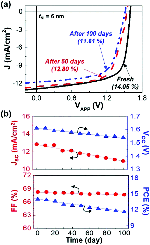 | ||
| Fig. 5 Shelf lifetime of tandem polymer solar cells. (a) Change of light (AM 1.5G, 100 mW cm−2) J–V curves during storage in a nitrogen-filled glove box for 100 days. (b) JSC, VOC, FF and PCE as a function of storage time: the decreasing rates were 1.9, 0.07, 0.6, and 2.5% per day for JSC, VOC, FF, and PCE, respectively. | ||
Conclusions
In conclusion, high efficiency tandem polymer solar cells were successfully fabricated by employing the MoO3/Ni/ZnO:PEOz interconnection layers. The individual front cells, which consist of newly synthesized conjugated polymer (PIDTT-BT) and PC71BM, exhibited PCE = 6.13%, while the polymer:nonfullerene rear cells delivered PCE = 11.83%. The hybrid (ZnO:PEOz) ECBLs were stably formed on the Ni interlayers without any damage on the bottom layers (front cells) and showed nanocratered surfaces. The performance of the tandem polymer solar cells was very sensitive to the thickness of the Ni interlayers. The JSC and FF values were strongly dependent on the Ni thickness, whereas the Ni thickness did only slightly affect the VOC value. The best PCE of 14.22% was achieved at the Ni thickness of 6 nm, which was assigned to the well-fabricated interconnection structures due to the ensemble of semi-transparent Ni interlayers and ZnO:PEO ECBLs with a particular nanocrater morphology. Thus the present structure of interconnection layer (MoO3/Ni/ZnO:PEOz) is expected to greatly contribute to the reproducible fabrication of tandem polymer solar cells toward higher efficiencies.Conflicts of interest
There are no conflicts to declare.Acknowledgements
This work was supported by the National Research Foundation (NRF) of Korea (2016H1D5A1910319, 2018R1D1A3B07046214, 2017M2A2A4A01071010, 2018R1D1A1B07051075, and Basic Science Research Program_2018R1A6A1A03024962).References
- G. Li, R. Zhu and Y. Yang, Nat. Photonics, 2012, 6, 153–161 CrossRef CAS.
- S. Günes, H. Neugebauer and N. S. Sariciftci, Chem. Rev., 2007, 107, 1324–1338 CrossRef PubMed.
- M. Jørgensen, K. Norrman and F. C. Krebs, Sol. Energy Mater. Sol. Cells, 2008, 92, 686–714 CrossRef.
- S. R. Forrest, Nature, 2004, 428, 911–918 CrossRef CAS PubMed.
- R. Søndergaard, M. Hösel, D. Angmo, T. T. Larsen-Olsen and F. C. Krebs, Mater. Today, 2012, 15, 36–49 CrossRef.
- Y. Kim, S. Cook, S. M. Tuladhar, S. A. Choulis, J. Nelson, J. R. Durrant, D. D. C. Bradley, M. Giles, I. Mcculloch, C.-S. Ha and M. Ree, Nat. Mater., 2006, 5, 197–203 CrossRef CAS.
- F. C. Krebs, Nanoscale, 2010, 2, 873–886 RSC.
- K. Ellmer, Nat. Photonics, 2012, 6, 809–817 CrossRef CAS.
- S. Nam, J. Seo, S. Woo, W. H. Kim, H. Kim, D. D. C. Bradley and Y. Kim, Nat. Commun., 2015, 6, 8929 CrossRef CAS PubMed.
- V. Vohra, K. Kawashima, T. Kakara, T. Koganezawa, I. Osaka, K. Takimiya and H. Murata, Nat. Photonics, 2015, 9, 403–408 CrossRef CAS.
- Z. Zheng, Q. Hu, S. Zhang, D. Zhang, J. Wang, S. Xie, R. Wang, Y. Qin, W. Li, L. Hong, N. Liang, F. Liu, Y. Zhang, Z. Wei, Z. Tang, T. P. Russell, J. Hou and H. Zhou, Adv. Mater., 2018, 30, 1801801 CrossRef PubMed.
- I. Shin, H. Ahn, J. H. Yun, J. W. Jo, S. Park, S.-Y. Joe, J. Bang and H. J. Son, Adv. Energy Mater., 2018, 8, 1870028 CrossRef.
- H. Han, J. Seo, M. Song, H. Kim and Y. Kim, J. Mater. Chem. A, 2018, 6, 7480–7487 RSC.
- X. Guo, N. Zhou, S. J. Lou, J. Smith, D. B. Tice, J. W. Hennek, R. P. Ortiz, J. T. L. Navarrete, S. Li, J. Strzalka, L. X. Chen, R. P. H. Chang, A. Facchetti and T. J. Marks, Nat. Photonics, 2013, 7, 825–833 CrossRef CAS.
- E. Park, J. Seo, H. Han, H. Kim and Y. Kim, Adv. Sci., 2018, 5, 1800331 CrossRef PubMed.
- K.-H. Kim, S. Park, H. Yu, H. Kang, I. Song, J. H. Oh and B. J. Kim, Chem. Mater., 2014, 26, 6963–6970 CrossRef CAS.
- M. Li, K. Gao, X. Wan, Q. Zhang, B. Kan, R. Xia, F. Liu, X. Yang, H. Feng, W. Ni, Y. Wang, J. Peng, H. Zhang, Z. Liang, H.-L. Yip, X. Peng, Y. Cao and Y. Chen, Nat. Photonics, 2017, 11, 85–90 CrossRef CAS.
- Y. Zhang, B. Kan, Y. Sun, Y. Wang, R. Xia, X. Ke, Y.-Q.-Q. Yi, C. Li, H.-L. Yip, X. Wan and Y. Cao, Adv. Mater., 2018, 30, 1707508 CrossRef PubMed.
- X. Xu, T. Yu, Z. Bi, W. Ma, Y. Li and Q. Peng, Adv. Mater., 2018, 30, 1703973 CrossRef PubMed.
- Y. Cui, H. Yao, B. Gao, Y. Qin, S. Zhang, B. Yang, C. He, B. Xu and J. Hou, J. Am. Chem. Soc., 2017, 139, 7302–7309 CrossRef CAS PubMed.
- J. You, L. Dou, K. Yoshimura, T. Kato, K. Ohya, T. Moriarty, K. Emery, C.-C. Chen, J. Gao, G. Li and Y. Yang, Nat. Commun., 2013, 4, 1446 CrossRef PubMed.
- Y. Zhou, C. Fuentes-Hernandez, J. W. Shim, T. M. Khan and B. Kippelen, Energy Environ. Sci., 2012, 5, 9827–9832 RSC.
- L. Meng, Y. Zhang, X. Wan, C. Li, X. Zhang, Y. Wang, X. Ke, Z. Xiao, L. Ding, R. Xia, H.-L. Yip, Y. Cao and Y. Chen, Science, 2018, 361, 1094–1098 CrossRef CAS PubMed.
- T. Ameri, G. Dennler, C. Lungenschmied and C. J. Brabec, Energy Environ. Sci., 2009, 2, 347–363 RSC.
- L. Dou, J. You, J. Yang, C.-C. Chen, Y. He, S. Murase, T. Moriarty, K. Emery, G. Li and Y. Yang, Nat. Photonics, 2012, 6, 180–185 CrossRef CAS.
- T. Stubhan, H. Oh, L. Pinna, J. Krantz, I. Litzov and C. J. Brabec, Org. Electron., 2011, 12, 1539–1543 CrossRef CAS.
- Y. Wang, Q. Luo, N. Wu, Q. Wang, H. Zhu, L. Chen, Y.-Q. Li, L. Luo and C.-Q. Ma, ACS Appl. Mater. Interfaces, 2015, 7, 7170–7179 CrossRef CAS PubMed.
- W. Qiu, R. Müller, E. Voroshazi, B. Conings, R. Carleer, H.-G. Boyen, M. Turbiez, L. Froyen, P. Heremans and A. Hadipour, ACS Appl. Mater. Interfaces, 2015, 7, 3581–3589 CrossRef CAS PubMed.
- F. Liu, S. Shao, X. Guo, Y. Zhao and Z. Xie, Sol. Energy Mater. Sol. Cells, 2010, 94, 842–845 CrossRef CAS.
- D. Bufford, H. Wang and X. Zhang, Acta Mater., 2011, 59, 93–101 CrossRef CAS.
- S. Chuang, C. Battaglia, A. Azcatl, S. McDonnell, J. S. Kang, X. Yin, M. Tosun, R. Kapadia, H. Fang, R. M. Wallace and A. Javey, Nano Lett., 2014, 14, 1337–1342 CrossRef CAS PubMed.
- Y. Zhou, C. Fuentes-Hernandez, J. Shim, J. Meyer, A. J. Giordano, H. Li, P. Winget, T. Papadopoulos, H. Cheun, J. Kim, M. Fenoll, A. Dindar, W. Haske, E. Najafabadi, T. M. Khan, H. Sojoudi, S. Barlow, S. Graham, J.-L. Brédas, S. R. Marder, A. Kahn and B. Kippelen, Science, 2012, 336, 327–332 CrossRef CAS PubMed.
- F. Liu, S. Shao, X. Guo, Y. Zhao and Z. Xie, Sol. Energy Mater. Sol. Cells, 2010, 94, 842–845 CrossRef.
- D. Bufford, H. Wang and X. Zhang, Acta Mater., 2011, 59, 93–101 CrossRef CAS.
- M. Wang, J. Song, X. Wu, X. Tan, B. Meng and S. Liu, J. Membr. Sci., 2016, 509, 156–163 CrossRef CAS.
- X. Xiong, D. Ding, D. Chen, G. Waller, Y. Bu, Z. Wang and M. Liu, Nano Energy, 2015, 11, 154–161 CrossRef CAS.
- J. Seo, S. Nam, H. Kim, D. D. C. Bradley and Y. Kim, Nanoscale Horiz., 2019, 4, 464–471 RSC.
- J. Seo, C. Lee, H. Kim and Y. Kim, Adv. Mater. Interfaces, 2018, 5, 1800912 CrossRef.
- J. Gilot, M. M. Wienk and R. A. J. Janssen, Adv. Funct. Mater., 2010, 20, 3904–3911 CrossRef CAS.
- J. Benduhn, K. Tvingstedt, F. Piersimoni, S. Ullbrich, Y. Fan, M. Tropiano, K. A. McGarry, O. Zeika, M. K. Riede, C. J. Douglas, S. Barlow, S. R. Marder, D. Neher, D. Spoltore and K. Vandewal, Nat. Energy, 2017, 2, 17053 CrossRef CAS.
- C.-C. Chueh, C.-Z. Li and A. K.-Y. Jen, Energy Environ. Sci., 2015, 8, 1160–1189 RSC.
- H.-L. Yip and A. K.-Y. Jen, Energy Environ. Sci., 2012, 5, 5994–6011 RSC.
- H. Ma, H.-L. Yip, F. Huang and A. K.-Y. Jen, Adv. Funct. Mater., 2010, 20, 1371–1388 CrossRef CAS.
- Y. Sun, J. H. Seo, C. J. Takacs, J. Seifter and A. J. Heeger, Adv. Mater., 2011, 23, 1679–1683 CrossRef CAS PubMed.
- P. Cheng, H. Bai, N. K. Zawacka, T. R. Andersen, W. Liu, E. Bundgaard, M. Jøgensen, H. Chen, F. C. Krebs and X. Zhan, Adv. Sci., 2015, 2, 1500096 CrossRef PubMed.
Footnote |
| † Electronic supplementary information (ESI) available. See DOI: 10.1039/c9nh00209j |
| This journal is © The Royal Society of Chemistry 2019 |