Vivid-colored silicon solar panels with high efficiency and non-iridescent appearance†
Chengang
Ji
 a,
Zhong
Zhang
a,
Taizo
Masuda
b,
Yuki
Kudo
b and
L. Jay
Guo
a,
Zhong
Zhang
a,
Taizo
Masuda
b,
Yuki
Kudo
b and
L. Jay
Guo
 *a
*a
aDepartment of Electrical Engineering and Computer Science, The University of Michigan, Ann Arbor, Michigan 48109, USA. E-mail: guo@umich.edu
bX-Frontier Division, Toyota Motor Corporation, Susono-shi, Shizuoka 471-8571, Japan
First published on 4th March 2019
Abstract
We present a novel approach towards fabricating bright-colored solar cells with excellent angular insensitivity while preserving high efficiency by topping a crystalline silicon solar panel with a trans-reflective color filtering device. The 5-layered filter exhibits a distinctive narrowband reflection, producing vivid colors (∼60% peak reflection) with an angle-invariant appearance up to ±60°. Simultaneously, it transmits the remaining broadband light spanning the whole solar spectrum onto the silicon solar panel underneath, leading to an overall high power conversion efficiency of decorative solar cells. This facile method with few layers can be used to decorate other types of solar panels for better building integration and simultaneously protect the active devices from environmental degradation. In addition, it can be easily replaced when the colored structures are damaged or a different color is desired, thus holding great potential for future building-integrated photovoltaics and automotive applications.
Conceptual insightsWe present a novel approach towards fabricating bright-colored solar cells with high power conversion efficiency (>10%) and excellent angular insensitivity by topping a crystalline silicon solar panel with a trans-reflective color filtering device. The proposed filter, simply comprising five layers with a high-index semiconductor layer sandwiched between two stacks of transparent dielectrics, exhibits a distinctive narrowband reflection (∼60% peak reflection) with an angle-invariant appearance up to ±60°. Simultaneously, it transmits the remaining light spanning the whole solar spectrum onto the underneath solar panel, therefore enabling both high final efficiency and narrowband reflection. The efficiency of the proposed solar panel is expected to be further improved if the passive filter is adjusted into an active solar cell by replacing the dielectrics with suitable transparent electrodes and hole/electron transport layers. The described approach has overcome various limitations in existing decorative photovoltaics, including environmental instability, insufficient color purity, angle-sensitive appearance, and low efficiency. More importantly, this facile method with few layers can be easily mass-produced and adopted in practical uses such as building-integrated photovoltaics and solar-powered cars, which bridges the gap between nano-optics and real-world applications. |
Introduction
Decorative solar cells have attracted considerable attention over the past decades due to their potential applications in building integrated photovoltaics (BIPVs) and automobiles to exploit the otherwise wasted energy.1–5 Traditional solar panels, which typically include a very thick semiconductor layer to efficiently absorb incident light, are unsuitable for decorating vehicle and building exteriors due to their black and dull appearance.6,7 Therefore, there is a strong need to develop multifunctional PVs that can offer aesthetic features.Various approaches, including dye sensitized solar cells (DSSCs) and organic PVs (OPVs), have been utilized to create colored solar cells.8–18 However, their color purity and tunability are heavily limited by available dyes and organic materials. Moreover, those organic devices have lifetime issues due to their material degradation especially after long-term exposure to moisture, oxygen and ultraviolet (UV) radiation. Recently, a scheme for integrating color filters with PV panels has been developed to simultaneously create colored appearance and electric power via spectrum-selective absorption.12,13,17,19–23 However, the color filters involved in those solar cells based on either Fabry–Pérot (F–P) cavities or plasmonic resonances produce colors that will vary with viewing angle and incident light polarization, which are undesirable for decorative applications. In addition, those nano-structured plasmonic colors are difficult to scale to practical large areas. To solve all the aforementioned issues, layered amorphous silicon (a-Si) hybrid solar cells featuring angle and polarization insensitive colors have been demonstrated.24–26 The non-iridescent colored appearance can be attributed to the nontrivial reflection phase change at the a-Si/metal interface, which consequently compensates for the propagation phase of light propagating through the ultrathin semiconductor layer (<30 nm).27–29 However, the power conversion efficiency (PCE) for the colored PV panel is significantly limited because only a small amount of light is absorbed. Most of the incident light gets reflected for generating subtractive colors (i.e., cyan, magenta, and yellow (CMY) colors), which adversely affects both the electrical performance and color purity. Creating narrowband red, green, and blue (RGB) reflective colors while absorbing the remaining light spanning a broadband range is of vital importance in achieving pure and efficient colored solar cells.21,30,31
In this work, we present a highly-efficient colored solar cell with high PCE employing a tandem configuration comprising a crystalline Si (c-Si) PV panel and a trans-reflective color filter atop. In particular, a blue device presents a highest PCE of ∼13.9%, which corresponds to only an ∼3.9% decrease compared to the initial c-Si panel, and the efficiencies of both green and red colored devices are also >10%. The color filtering device simply consisting of five layers exhibits a distinctive narrowband reflection. A previous approach of using metal films to achieve high reflection in a passive color is not acceptable due to little light transmission.32 In contrast, the high reflection (∼60% reflection peak) achieved in our structure is mainly attributed to the high-index a-Si semiconductor sandwiched between two stacks of transparent dielectrics. By avoiding using any reflective metals, the designed structures can transmit a large portion of the solar spectrum onto the c-Si module beneath with a symmetric gradient index profile with respect to the middle a-Si layer, thereby achieving an overall high efficiency and final narrowband reflection by suppressing the undesired sideband reflection. The entire colored solar module presents a distinctive color with high angular insensitivity up to ±60° due to the high refractive indices of the materials involved in the filter structure, making it behave like a normal painted color used in decoration applications. This method offers great simplicity over traditional one dimensional (1D) photonic crystals (PCs), which typically consist of tens of layers, making it suitable to be mass-produced to decorate any kinds of solar panels in the foreseeable future. It also protects active solar devices from environmental degradation and can be easily replaced when damage occurs or a different color is desired.
Results and discussion
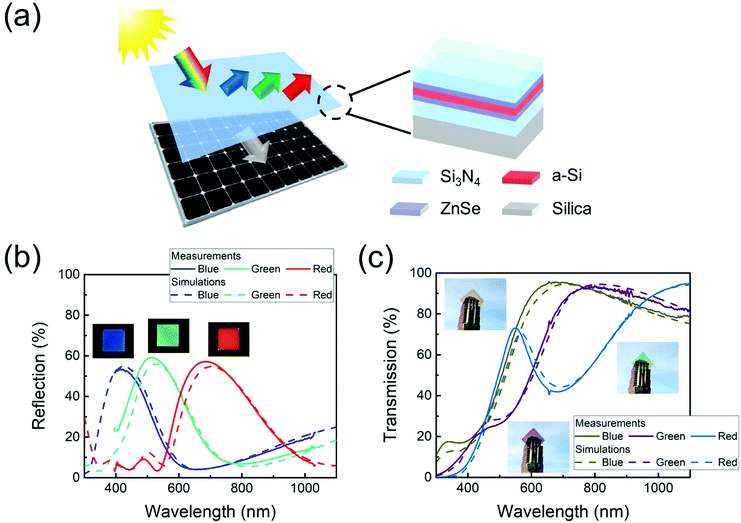
Fig. 1(a) shows a schematic diagram of the proposed highly-efficient colored solar cells, which integrate c-Si solar panels with decorative trans-reflective filters atop. The detailed configuration of the angle-invariant trans-reflective filter that can generate a distinctive reflection color as well as broadband high transmission is provided in the inset. As depicted in the plot, it consists of five layers on a transparent silica substrate with a thin a-Si layer sandwiched between two stacks of transparent dielectrics (zinc selenide (ZnSe)/silicon nitride (Si3N4)), forming a symmetric graded index profile, which consequently results in remarkable transmission across the whole solar spectrum to be harvested by the c-Si PV beneath. As presented in Fig. 1(b), the designed colors can reach peak reflections of ∼60% at different wavelengths. The high reflection can be attributed to the high refractive index of a-Si, which is elucidated in Fig. S1 (ESI†) by comparing the reflection spectra of blue colored devices as an example employing materials of different refractive indices as the middle layers. Different reflection colors can be created by simply adjusting the thickness of each layer and the detailed configurations of the three colored devices are summarized in Table 1. It can be clearly observed that thicker films are required to generate reflection colors at longer wavelengths. As the a-Si refractive index decreases at longer wavelengths (as shown in Fig. S2, ESI†), the a-Si thicknesses employed in green and red colored devices are intentionally increased compared to the blue colored filter to maintain the high reflection intensity. The insets in Fig. 1(b) show the fabricated RGB colored samples on top of a c-Si solar panel under ambient illumination, exhibiting bright and distinctive colors at normal incidence. Fig. 1(c) presents the efficient and broadband transmission spectra of all three devices and their high transparency can be clearly visualized in the inset photographs of the fabricated samples. Both the reflection and transmission plots show excellent consistency between the calculated and measured results, thus validating our design principles. All the calculations are performed based on the transfer matrix method with the refractive indices of the materials characterized using a spectroscopic ellipsometer (M-2000, J. A. Woollam), which are provided in Fig. S2 (ESI†).33| Material | Si3N4 | ZnSe | a-Si | ZnSe | Si3N4 |
|---|---|---|---|---|---|
| Blue (nm) | 95 | 15 | 13 | 15 | 95 |
| Green (nm) | 110 | 20 | 25 | 20 | 110 |
| Red (nm) | 150 | 30 | 40 | 30 | 150 |
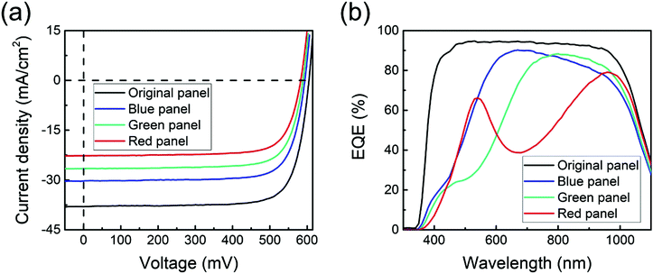
Fig. 2(a) presents the measured current density–voltage (J–V) characteristics of the colored solar panels, which are realized by integrating the passive filter with the c-Si panel beneath. Due to the largest amount of light transmitted through the top filter harvested by the c-Si cell (as shown in Fig. 1(c)), the blue colored PV system shows a highest PCE of ∼13.9% with a short circuit current density (Jsc) of ∼30.3 mA cm−2, an open circuit voltage (Voc) of ∼594.1 mV, and a fill factor (FF) of ∼77.2%, which is only ∼3.9% lower than the efficiency of the original c-Si solar cell without any color filter covering (Jsc ∼ 38.0 mA cm−2, Voc ∼ 604.7 mV, and FF ∼ 77.5%, corresponding to a PCE of ∼17.8%). Decent efficiencies have also been achieved for the green (PCE ∼ 12.0%) and red (PCE ∼ 10.1%) colored cells and the performances are summarized in Table 2 for comparison. The performances have effectively overcome the low efficiency limitations of typical colored PVs and open up a new path to their extensive use for a wide variety of applications. The detailed measurement method is provided in the Methods section and Fig. S3 (ESI†). As discussed above, more transmitted light will be harvested by the underneath c-Si solar cell upon lowering the reflective color intensity by employing a thinner a-Si layer in the middle, which is one effective approach to enhance the overall PCE of the colored solar module. In addition, the efficiency can be further improved when an index-matching layer is added between the passive filter and the underneath c-Si cell to reduce the ∼4.0% reflection from the back of the silica substrate or utilizing a more efficient solar panel beneath instead of the c-Si solar cell. The measured external quantum efficiency (EQE) spectra of the RGB colored solar panels are displayed in Fig. 2(b). These curves exhibit very similar shapes to the corresponding transmission spectra provided in Fig. 1(c), which clearly indicates that most of the transmitted light through the top filters gets absorbed by the c-Si panel beneath. The calculated Jsc values of these colored solar panels from the measured EQE data are ∼30.5 (blue), 26.2 (green), and 22.5 (red) mA cm−2, respectively, which are in excellent agreement with the measured results in J–V characterization. The EQE spectrum of the original c-Si panel without any covering is also provided in the plot as a comparison and its calculated Jsc is 38.1 mA cm−2.
| J sc (mA cm−2) | V oc (mV) | FF (%) | PCE (%) | |
|---|---|---|---|---|
| Original panel | 38.0 | 604.7 | 77.5 | 17.8 |
| Blue panel | 34.2 | 594.1 | 77.2 | 13.9 |
| Green panel | 26.5 | 588.7 | 76.8 | 12.0 |
| Red panel | 22.7 | 582.9 | 76.0 | 10.1 |
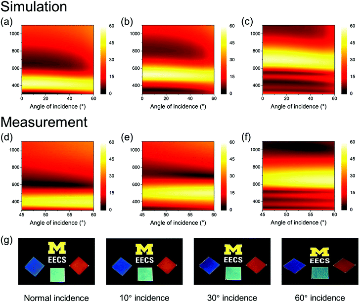
The calculated angle-resolved reflection spectra of the designed RGB colored solar panels under unpolarized light illumination are shown in Fig. 3(a)–(c), showing great consistency with the measurements in Fig. 3(d)–(f). From both the simulation and measurement results, it can be seen that the reflection peaks of all devices remain constant with respect to the viewing angle up to ±60°, which clearly indicates the angular robust performance and is a direct result of the high indices of the materials (i.e., a-Si, ZnSe, and Si3N4) involved in our designs.26,34 Considering that only the material deposition process is required, the proposed structure is an excellent candidate for decorative PV applications due to its simple and cost-effective manufacturing process. The photographs of the fabricated samples against a black background under ambient light illumination in Fig. 3(g) show that stable colors can be viewed at various angles, which further validates the angular invariant properties of our designs. Note that the black background is utilized to absorb the transmitted light, thus avoiding its interference with the reflection color.
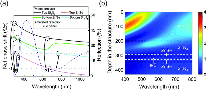
The broadband transmission and colored appearance of the designed trans-reflective filters atop can be explained by multiple resonances at various wavelengths in those dielectric stacks. The blue colored device is used as an example for explanation in the following discussions. The same working and design principles also apply to the other colored structures as presented in Fig. S4 (ESI†). In Fig. 4(a), the net phase shift, which includes two reflection phase shifts acquired upon reflection from both the top and bottom interfaces and the propagation phase accumulated within the layer, is plotted for each dielectric layer. Transmission is efficiently enhanced at those wavelengths where the net phase shift is equal to a multiple of 2π, i.e., creating Fabry–Pérot (F–P) resonances to reduce the reflection, which consequently induces transmission. In particular, the reflection dip at ∼300 nm results from the resonances inside all four dielectric layers, i.e., resonances at 292 nm and 294 nm in the top and bottom Si3N4 layers, respectively, and resonances at 318 nm and 317 nm in the top and bottom ZnSe layers, respectively. Reflections at longer wavelengths are well suppressed with the broadband transmission owing to the multiple resonances at discrete wavelengths (resonances at 653 nm in the top Si3N4, at 663 nm in the top ZnSe, and at 754 nm in the bottom Si3N4). As a result, only light within the blue color range, where no transmission resonances are excited, gets effectively reflected, thereby generating a distinctive color appearance. The calculated electric field distribution inside the structure as a function of wavelength is depicted in Fig. 4(b). The strong reflection within the short wavelength range from 400 to 500 nm clearly indicates the blue color reflection of the designed structure.
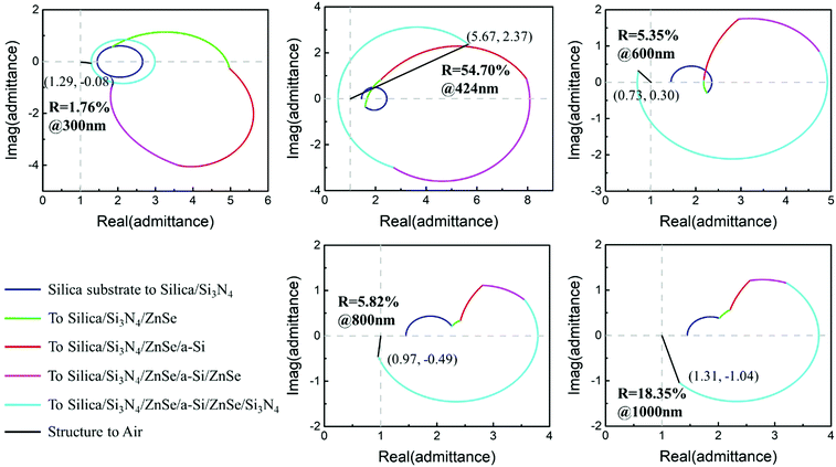
On the other hand, the high efficiency of the broadband transmission results from the anti-reflection (AR) effects of the dielectric layers featuring a gradient index profile. This can be clearly validated by plotting the optical admittance diagram, which provides an effective way to visually represent the optical surface admittance of the multilayered structure. The optical admittance  is the inverse of the impedance, with ε and μ being the permittivity and permeability, respectively, and equal to the material complex refractive index due to the negligible magnetic effects at optical frequencies.35 The admittance locus is a circle for transparent dielectrics and perfect electric conductors, and a spiral for absorbing materials such as semiconductors and real metals. The admittance of the structure starts with the substrate and rotates on the circular or spiral trajectory as the thickness increases. The distance between the termination admittance point of the layered structure and the admittance of air (1,0) determines the reflection intensity by
 | (1) |
| Ref. | Color model | Peak reflectiona | PCE (%) | Angular sensitivity |
|---|---|---|---|---|
| a The peak reflection values are listed only for RGB devices as they are not a decisive factor affecting the color purity of CMY colors. | ||||
| This work | RGB | ∼60% for all colors | 10.1–13.9 | Low |
| 18 | RGB | ∼20–60% | 4.5–8.8 | High |
| 19 | CMY | — | 0.6–1.6 | High |
| 21 | RGB | ∼45–60% | 7.7–10.1 | Low |
| 24 | CMY | — | 1.9–2.8 | Low |
Conclusions
In conclusion, we have demonstrated a new approach towards fabricating high-performance colored solar cells by integrating a trans-reflective filter on the top of a c-Si solar panel. The filter design simply consists of 5 layers, where a lossy semiconductor with a high refractive index is sandwiched between two stacks of dielectrics. A distinctive reflection color together with the overall high transmission across the whole solar spectrum, where the latter is subsequently harvested by the c-Si panel beneath and results in a high final PCE, has been generated utilizing the filter featuring a gradient index profile. Due to the high index materials involved in the filter module, the whole system presents high brightness and a high angle invariant appearance up to ±60°. As the middle a-Si is a potential active layer, the efficiency of the proposed colored solar panel can be further enhanced when the passive filter is adapted into an active solar cell by replacing the dielectrics with transparent electrodes and hole/electron transport layers, thus forming four-terminal PV devices. The colored structures developed in this work requiring only mechanical integration are applicable to any type of solar panel and can be easily replaced when they are damaged or a different color is desired. In addition, they can also function as protection barriers against UV radiation and moisture especially when being used to decorate OPVs and perovskite solar cells. Considering that only the deposition method is involved in the fabrication of the designed structure, the scheme described here featuring high PCE has overcome the limitations of typical colored solar cells and could open up new possibilities for various applications in the future, including innovative solar-harvesting coatings, solar buildings, and next-generation solar-powered cars.Methods
Materials
ZnSe is deposited by e-beam evaporation at room temperature with a rate of 3.0 Å s−1. Si3N4 and a-Si are deposited by plasma-enhanced chemical vapor deposition (PECVD) at rates of 4.0 Å s−1 and 0.7 Å s−1 at a temperature of 260 °C, respectively.Simulations
Optical simulations for calculating the spectral reflection and transmission, angle-resolved spectra, electric field intensity distributions, and the net phase shift within each dielectric layer are based on the transfer matrix method with the refractive indices of materials calibrated using a spectroscopic ellipsometer (M-2000, J. A. Woollam).Optical and electrical characterization
The reflection spectrum at normal incidence is obtained with a thin-film measurement instrument (F20, Filmetrics) integrated with a spectrometer and a white light source. The measurements of angle-resolved reflection spectra from 45° to 60° as well as the transmission spectrum at the normal incidence are performed with the spectroscopic ellipsometer (M-2000, J. A. Woollam).A commercial back contact c-Si solar panel (∼125 mm × 125 mm, Maxeon®, SunPower Corporation) is covered using aluminum foil with a 16 mm × 16 mm opening at the center for the integration of 25 mm × 25 mm passive filters atop. Then the current density–voltage (J–V) performance of the integrated colored solar cell is recorded under AM1.5 simulated sunlight (∼100 mW cm−2) illumination by connecting an MP-160 (EKO Instruments) to electrodes (a detailed setup is provided in Fig. S3, ESI†). The external quantum efficiency (EQE) measurements were performed in the CEP-25RR measurement system (Bunkoukeiki, Co., Ltd).
Conflicts of interest
There are no conflicts to declare.Acknowledgements
The authors would like to thank Toyota Motor Corporation for the support of this work.Notes and references
- H. Presting and U. König, Mater. Sci. Eng., C, 2003, 23, 737–741 CrossRef.
- A. Henemann, Renewable Energy Focus, 2008, 9, 14–19 CrossRef.
- C.-M. Lai and Y.-P. Lin, Energies, 2011, 4, 948–959 CrossRef.
- T. Masuda, S. Hirai, M. Inoue, J. Chantana, Y. Kudo and T. Minemoto, IEEE J. Photovolt., 2018, 8, 1326–1330 Search PubMed.
- T. Masuda, Y. Kudo and D. Banerjee, Coatings, 2018, 8, 282 CrossRef.
- T. Masuda, K. Araki, K. Okumura, S. Urabe, Y. Kudo, K. Kimura, T. Nakado, A. Sato and M. Yamaguchi, Sol. Energy, 2017, 146, 523–531 CrossRef.
- K. Araki, L. Ji, G. Kelly and M. Yamaguchi, Coatings, 2018, 8, 251 CrossRef.
- A. Hinsch, W. Veurman, H. Brandt, K. Flarup Jensen and S. Mastroianni, ChemPhysChem, 2014, 15, 1076–1087 CrossRef CAS PubMed.
- L. M. Gonçalves, V. de Zea Bermudez, H. A. Ribeiro and A. M. Mendes, Energy Environ. Sci., 2008, 1, 655–667 RSC.
- X. Wang, L. Zhi and K. Müllen, Nano Lett., 2008, 8, 323–327 CrossRef CAS PubMed.
- Z. He, C. Zhong, S. Su, M. Xu, H. Wu and Y. Cao, Nat. Photonics, 2012, 6, 591 CrossRef.
- G. Xu, L. Shen, C. Cui, S. Wen, R. Xue, W. Chen, H. Chen, J. Zhang, H. Li, Y. Li and Y. Li, Adv. Funct. Mater., 2017, 27, 1605908 CrossRef.
- J.-H. Lu, Y.-H. Lin, B.-H. Jiang, C.-H. Yeh, J.-C. Kao and C.-P. Chen, Adv. Funct. Mater., 2017, 28, 1703398 CrossRef.
- J. H. Noh, S. H. Im, J. H. Heo, T. N. Mandal and S. I. Seok, Nano Lett., 2013, 13, 1764–1769 CrossRef CAS PubMed.
- Y. Li, J.-D. Lin, X. Che, Y. Qu, F. Liu, L.-S. Liao and S. R. Forrest, J. Am. Chem. Soc., 2017, 139, 17114–17119 CrossRef CAS PubMed.
- A. Colsmann, A. Puetz, A. Bauer, J. Hanisch, E. Ahlswede and U. Lemmer, Adv. Energy Mater., 2011, 1, 599–603 CrossRef CAS.
- G. E. Eperon, V. M. Burlakov, A. Goriely and H. J. Snaith, ACS Nano, 2014, 8, 591–598 CrossRef CAS PubMed.
- W. Zhang, M. Anaya, G. Lozano, M. E. Calvo, M. B. Johnston, H. Míguez and H. J. Snaith, Nano Lett., 2015, 15, 1698–1702 CrossRef CAS PubMed.
- H. J. Park, T. Xu, J. Y. Lee, A. Ledbetter and L. J. Guo, ACS Nano, 2011, 5, 7055–7060 CrossRef CAS PubMed.
- Y.-H. Chen, C.-W. Chen, Z.-Y. Huang, W.-C. Lin, L.-Y. Lin, F. Lin, K.-T. Wong and H.-W. Lin, Adv. Mater., 2013, 26, 1129–1134 CrossRef CAS PubMed.
- K.-T. Lee, J.-Y. Jang, J. Zhang, S.-M. Yang, S. Park and H. J. Park, Sci. Rep., 2017, 7, 10640 CrossRef PubMed.
- K. Diest, J. A. Dionne, M. Spain and H. A. Atwater, Nano Lett., 2009, 9, 2579–2583 CrossRef CAS PubMed.
- Y.-T. Yoon, H.-S. Lee, S.-S. Lee, S. H. Kim, J.-D. Park and K.-D. Lee, Opt. Express, 2008, 16, 2374–2380 CrossRef CAS PubMed.
- K.-T. Lee, J. Y. Lee, S. Seo and L. J. Guo, Light: Sci. Appl., 2014, 3, e215 CrossRef.
- J. Y. Lee, K.-T. Lee, S. Seo and L. J. Guo, Sci. Rep., 2014, 4, 4192 CrossRef PubMed.
- C. Ji, K.-T. Lee, T. Xu, J. Zhou, H. J. Park and L. J. Guo, Adv. Opt. Mater., 2017, 5, 1700368 CrossRef.
- M. A. Kats, R. Blanchard, P. Genevet and F. Capasso, Nat. Mater., 2013, 12, 20–24 CrossRef CAS PubMed.
- M. A. Kats and F. Capasso, Laser Photonics Rev., 2016, 10, 735–749 CrossRef CAS.
- K.-T. Lee, S. Seo, J. Y. Lee and L. J. Guo, Adv. Mater., 2014, 26, 6324–6328 CrossRef CAS PubMed.
- E.-H. Cho, H.-S. Kim, J.-S. Sohn, C.-Y. Moon, N.-C. Park and Y.-P. Park, Opt. Express, 2010, 18, 27712–27722 CrossRef CAS PubMed.
- M. J. Uddin and R. Magnusson, Opt. Express, 2013, 21, 12495–12506 CrossRef PubMed.
- C. Yang, W. Shen, Y. Zhang, K. Li, X. Fang, X. Zhang and X. Liu, Sci. Rep., 2015, 5, 9285 CrossRef CAS PubMed.
- L. A. A. Petterson, L. S. Roman and O. Inganäs, J. Appl. Phys., 1999, 86, 487–496 CrossRef.
- C. Ji, K.-T. Lee and L. J. Guo, Opt. Lett., 2019, 44, 86–89 CrossRef PubMed.
- H. A. Macleod, Thin-film optical filters, CRC Press, Boca Raton, FL, USA, 2001 Search PubMed.
Footnote |
| † Electronic supplementary information (ESI) available. See DOI: 10.1039/c8nh00368h |
| This journal is © The Royal Society of Chemistry 2019 |

