
 Open Access Article
 This Open Access Article is licensed under a Creative Commons Attribution-Non Commercial 3.0 Unported Licence
Novel electroblowing synthesis of submicron zirconium dioxide fibers: effect of fiber structure on antimony(V) adsorption†
Johanna
Paajanen‡
 *a,
Satu
Lönnrot‡
a,
Mikko
Heikkilä
a,
Kristoffer
Meinander
b,
Marianna
Kemell
a,
Timo
Hatanpää
a,
Kaisu
Ainassaari
c,
Mikko
Ritala
a and
Risto
Koivula
a
*a,
Satu
Lönnrot‡
a,
Mikko
Heikkilä
a,
Kristoffer
Meinander
b,
Marianna
Kemell
a,
Timo
Hatanpää
a,
Kaisu
Ainassaari
c,
Mikko
Ritala
a and
Risto
Koivula
a
aDepartment of Chemistry, FI-00014 University of Helsinki, P.O. Box 55, Finland. E-mail: johanna.paajanen@helsinki.fi
bDepartment of Applied Physics, FI-00076 AALTO, P.O. Box 15100, Finland
cEnvironmental and Chemical Engineering, Faculty of Technology, FI-90014 University of Oulu, P.O. Box 4300, Finland
First published on 8th October 2019
Abstract
Both stable and radioactive antimony are common industrial pollutants. For antimonate (Sb(V)) removal from industrial waste water, we synthesized submicron zirconium dioxide (ZrO2) fibers by electroblowing and calcination of the as-electroblown fibers. The fibers are amorphous after calcination at 300 and 400 °C and their average diameter is 720 nm. The fibers calcined at 500 to 800 °C have an average diameter of 570 nm and their crystal structure transforms from tetragonal to monoclinic at the highest calcination temperatures. We investigated Sb(V) adsorption capacity of the synthesized ZrO2 fibers as a function of pH, adsorption isotherm at pH 6 and adsorption kinetics at pH 7. The tetragonal ZrO2 fibers calcined at 500 °C exhibited the best potential for Sb(V) remediation with Sb(V) uptake of 10 mg g−1 at pH 2 and a maximum Sb(V) uptake of 8.6 mg g−1 in the adsorption isotherm experiment. They also reached 30% of 7 days' Sb(V) uptake in only a minute. The adsorption kinetics followed the Elovich model.
1. Introduction
Large quantities of antimony are used industrially in different applications. Addition of antimony to lead increases the hardness and mechanical strength of the alloy. Antimony is also used in pigments, as an oxidation catalyst and in therapeutic agents. The majority of antimony is used as a flame retarding additive in a wide variety of products.1 In total 144![[thin space (1/6-em)]](https://www.rsc.org/images/entities/char_2009.gif) 000 tons of Sb were produced by mines in 2016.2 Anthropogenic pollution comes mainly from mining and smelting of antimony. In highly polluted areas the concentration of soluble antimony can be over 100 times the natural level of 1 μg L−1.1 Antimony is toxic and carcinogenic, and its removal from contaminated water is essential. The European Union and the Environmental Protection Agency of the United States have determined the maximum allowed concentration of antimony in drinking water to be 5 and 6 μg L−1, respectively.3,4 Antimony is also problematic in the nuclear power industry. Three antimony isotopes 122Sb, 124Sb and 125Sb are produced through neutron activation of corrosion products in a nuclear reactor. The isotopes emit high-energy gamma rays potentially causing a significant radiation dose to the personnel.5 It is estimated that in Loviisa Nuclear Power Plant (PWR, VVER-440), Finland, about 50% of the radiation dose received by personnel during the annual maintenance is caused by radioactive antimony isotopes.6,7
000 tons of Sb were produced by mines in 2016.2 Anthropogenic pollution comes mainly from mining and smelting of antimony. In highly polluted areas the concentration of soluble antimony can be over 100 times the natural level of 1 μg L−1.1 Antimony is toxic and carcinogenic, and its removal from contaminated water is essential. The European Union and the Environmental Protection Agency of the United States have determined the maximum allowed concentration of antimony in drinking water to be 5 and 6 μg L−1, respectively.3,4 Antimony is also problematic in the nuclear power industry. Three antimony isotopes 122Sb, 124Sb and 125Sb are produced through neutron activation of corrosion products in a nuclear reactor. The isotopes emit high-energy gamma rays potentially causing a significant radiation dose to the personnel.5 It is estimated that in Loviisa Nuclear Power Plant (PWR, VVER-440), Finland, about 50% of the radiation dose received by personnel during the annual maintenance is caused by radioactive antimony isotopes.6,7
Antimony exists mainly in the two oxidation states of antimonite Sb(III) and antimonate Sb(V).1 Sb(V) is prevalent in oxidising conditions but it is also reported to be found in anaerobic conditions.1,8 Sb(V) has two hydroxyl species, Sb(OH)5 which is prevalent in acidic conditions and Sb(OH)6− which exists above pH 3.9 Also SbO2+, H[Sb(OH)6], HSbO3 and SbO3− species have been suggested.10 In a reducing environment, Sb(III) is prevalent and it has three hydroxyl species, Sb(OH)2+, Sb(OH)3 and Sb(OH)4−, which are in the order from acidic to alkaline.9 Sb(III) is relatively easy to remove by conventional cation exchangers. As a negatively charged ion, Sb(OH)6− is more mobile and soluble than Sb(III) and is not effectively retained by conventional ion exchangers. For this reason, Sb(V) was selected as the subject for this study.11
Adsorption has proven to be a cost-effective and simple manner to purify Sb contaminated waters.12 Adsorbents can be divided into inorganic and organic groups that can be produced by gathering from nature, manufacturing synthetically and collecting from residue or waste streams. For example, activated carbon prepared from peanut shell has been used for Cr(VI) removal,13 iron oxide nanocomposites for Pb(II), Cd(II), Cr(III) and Co(II) separation14,15 and iron oxide metal–organic framework for U(VI) and Th(IV) sequestration.16 Powderous, granular and fibrous zirconium dioxide have exhibited high Sb(V) adsorption capacities.17–19 ZrO2 has a good performance even in a chemically harsh environment by tolerating acidic and alkaline as well as oxidising and reducing conditions and it is also a nontoxic substance.18,19
Nano- and submicron fibers have some unique characteristics such as a good tensile strength and large specific surface area due to a small diameter and porous structure.20,21 Mechanical properties of the fibers could make it possible to use them in flow-through separation columns even with high flow rates and the large specific surface area could ensure a good adsorption capacity. Nano- and submicron fibers would also be an excellent adsorbent for radioactive waste water treatment in the nuclear industry, as due to their small size they would significantly reduce the volume of radioactive waste that requires a permanent repository in the environment. Hence, zirconium dioxide fibers have potential for an efficient and eco-friendly adsorbent for various industrial applications.
Template immersion in zirconia sol,22 electrospinning,23–28 sol–gel method,29 high-speed centrifugal spinning30 and solution blowing31 have been utilized for fabricating nano- and microscale ZrO2 fibers. So far, the most common method to synthesize ZrO2 fibers has been electrospinning (ES). In electrospinning, a pump delivers a polymer containing solution through a needle to which a high voltage power supply is connected. The applied high voltage induces electric charges within the solution, and the solution jet stretches and travels towards a grounded collector with a lower potential. During the stretching of the solution jet, the entangled polymer chains prevent the jet from breaking up thus maintaining a continuous fibrous jet. Electrospinning is a favoured technique because the morphology and properties of the fibers can be controlled, it is simple and cost-efficient, and the process is reproducible and upscalable for industry.21,32–34
Solution blowing (SB) or solution blow spinning (SBS) is a fiber fabrication process that exploits two parallel concentric fluid streams: a polymer and other reactants dissolved in a volatile solvent and a pressurized gas that flows around the solution, forming fibers that are deposited in the direction of the gas flow. Generally, an SBS setup consists of a compressed gas source for delivering the carrier gas and a pump for the precursor solution.35 Solution blow spinning enables deposition of fibers onto both planar and nonplanar substrates with a production rate that is up to 20 times faster than the conventional electrospinning. SBS usually produces fibers that are aligned in bundles, whereas electrospinning yields un-aligned, single nanofibers that are tightly packed and highly entangled. Solution blown fiber mats also have a lower modulus than electrospun fiber mats.36–38
In electroblowing (EB, blowing-assisted electrospinning, electro-blown spinning) fiber formation is driven by both electrostatic forces and high velocity gas flow.39 In other words, electroblowing is a combined technique of electrospinning and solution blowing and has the advantages of both. Due to the assisting gas flow, the production rate of electroblowing can be even 30 times that of electrospinning.40 In electrospinning, the feed rate of the precursor solution is usually 0.1 to 5 mL h−1 while in electroblowing the feed rate may be as high as 150 mL h−1.41 The applied high voltage causes electrostatic repulsions between the polymer fibers and thereby prevents the bundling of the fibers as typical for solution blowing and results in single randomly oriented and highly entangled fibers.37,42 Since electrospinning has proven to be upscalable to industry, the same should be feasible for electroblowing too.
Herein we report on the synthesis of submicron zirconium dioxide fibers by electroblowing and calcination of the as-electroblown material. Moreover, we report on the effects of the crystal structure of the synthesized zirconia fibers on sorption of antimony(V) from an aqueous solution. To the authors' knowledge there are no prior reports on how the crystal structure of ZrO2 fibers affects their ability to adsorb Sb(V).
2. Experimental
2.1. Materials
The precursor solutions for the electroblowing experiments were made from zirconyl chloride octahydrate (ZrOCl2·8H2O, Alfa Aesar, 98%), polyvinylpyrrolidone (PVP, (C6H9NO)n, Mw = 1300000, Alfa Aesar), ethanol (C2H5OH, 96 vol%, GPR RECTAPUR) and deionized water.
In adsorption experiments KSb(OH)6 (Sigma-Aldrich) and NaNO3 (>99%, VWR Chemicals) were used. 200 mg L−1 Sb(V) stock solution was made by dissolving KSb(OH)6 in deionized water. In all solutions and samples deionized water (18.2 MΩ cm at 25 °C, Millipore) was used. Samples were diluted for Sb(V) concentration measurement with hydrochloric acid (30%, Merck Suprapur) and nitric acid (67–69%, Romil SpA super purity).
2.2. Synthesis and characterisation of the ZrO2 fibers
The precursor solutions for the electroblowing were prepared by dissolving an appropriate amount of ZrOCl2·8H2O first in deionized water followed by mixing with a certain amount of beforehand prepared 12 wt% PVP/EtOH solution. The mass fractions of the individual components in the precursor solutions were 11 wt% for ZrOCl2·8H2O, 31 wt% for deionized H2O, 7 wt% for PVP and 51 wt% for ethanol. The solutions were stirred at room temperature with a magnetic stirrer until they became clear and homogeneous.The solutions were electroblown into fibers using a self-made equipment.43 Compressed air was delivered through a custom-made 3 mm metal nozzle at a rate of 30 NL min−1. A 27 G (inner diam. 0.21 mm) needle was pushed through the nozzle and placed at the center of the gas flow protruding ca. 2 mm from the aperture. The needle was attached to a 10 mL syringe and the solution was fed through the needle at a rate of 15 mL h−1 with a syringe pump (KDS Legato™). Thus the feed rate was 15 to 150 times as high as reported for the electrospinning of ZrO2 fibers.23–26,28 A voltage of 15 kV was applied to the nozzle and needle. The solution jet ejected from the needle tip was collected as fibrous mats on grounded metal grid collectors comprising a cylindrical collector with a diameter of 50 cm and a planar back collector at an 80 cm distance from the nozzle. The collectors were placed inside a box with an additional drying air flow (40 NL min−1) for enhanced solvent vapour removal from the box through holes located behind the back collector. The relative humidity remained below 15% within the box during the experiments. The electroblowing process worked well i.e. the solution jet remained stable in repeated experiments. The as-electroblown fibrous mats were detached from the collectors and calcined in an ashing furnace in air at 300, 400, 500, 600, 700 and 800 °C for 6 h with a heating rate of 1 °C min−1. The yield of pure fibrous ZrO2 was at best 0.63 g per hour of electroblowing.
The calcined fibers were imaged by field emission scanning electron microscopy (FESEM) and scanning transmission electron microscopy (STEM) with a Hitachi S-4800 field emission SEM. Elemental analysis of the fibers before and after adsorption of Sb(V) was conducted with an Oxford INCA 350 energy dispersive X-ray microanalysis (EDX) system. Prior to the characterization by FESEM and EDX a 4 nm layer of Au/Pd was sputtered on the samples to improve image quality. The average diameters of the fibers were determined with an ImageJ software. The crystallinity and crystalline phases of the fibers were analysed with a PANalytical X'Pert PRO MPD X-ray diffractometer using Cu Kα radiation and focusing optics. The relative amounts of different crystalline phases and the mean crystallite sizes were determined from the XRD data by the Rietveld refinement using a MAUD software.44 The oxidation state of zirconium, the presence of hydroxyl groups on the surface of the fibers and the oxidation state of adsorbed antimony were analysed by X-ray photoelectron spectroscopy (XPS) with an Omicron ARGUS spectrometer operated at a pass energy of 20 eV. Samples were illuminated using Mg Kα radiation. Binding energies were calibrated using the C 1s peak of ambient hydrocarbons at 284.8 eV. Peaks were fitted using a CasaXPS software. A thermogravimetric analysis (TGA) of the as-electroblown fibers was conducted with a NETZSCH STA 449 F3 Jupiter® system using a heating rate of 10 °C min−1 in a temperature range of 25 to 1000 °C in air (80 mol%) and N2 (20 mol%, the purge gas). The specific surface areas of selected samples were measured by N2 physisorption at 77 K with a Micromeritics ASAP 2020 Gas sorption analyser.
2.3. Adsorption studies
 | (1) |
3. Results and discussion
3.1. SEM, STEM and EDX analysis of the ZrO2 fibers
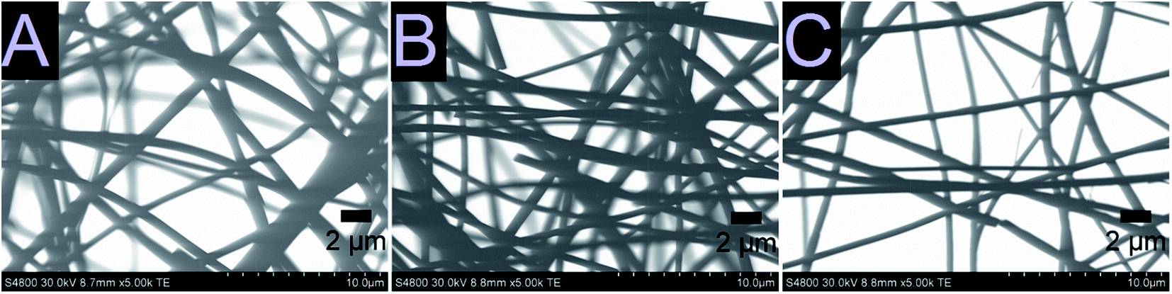
As-electroblown ZrO2/PVP fibers and ZrO2 fibers calcined at 700 °C are shown in Fig. 1. FESEM images of the uncalcined ZrO2/PVP fibers and ZrO2 fibers calcined at 400, 500 and 800 °C are presented in Fig. 2 and 3. The uncalcined fibers possessed the highest average diameter, 1260 nm. As to the calcined fibers, the average diameter seemed to depend on the calcination temperature. After calcination at the lower temperatures there were apparently some polymer residues left since the average diameters of the fibers calcined at 300 to 400 °C and 500 to 800 °C were 720 and 570 nm, respectively. All the fibers seemed to be solid and no fused fibers nor many beads were observed. The solid nature of the fibers was confirmed by scanning transmission electron microscopy (STEM) (Fig. 4). However, there were differences in the morphology of the fibers calcined at different temperatures. The uncalcined fibers as well as the fibers calcined at 300 to 500 °C were round in cross section and had a smooth surface. The fibers calcined at 600 to 800 °C were less round in cross section and their surface was rougher. The roughness of the surface increased with increasing calcination temperature; the fibers calcined at 700 and 800 °C seemed to consist of nanogranules connected together. The granular surface of the ZrO2 fibers calcined at 800 °C is shown in Fig. 3D. The results of the elemental analysis of the fibers before and after adsorption of Sb(V) are presented in the ESI (Fig. S1 to S3†). | ||
| Fig. 1 As-electroblown ZrO2/PVP fibers (on the left) and pure ZrO2 fibers calcined in air at 700 °C (on the right) on 150 mm silicon wafers. The calcined fiber mats have shrunk due to the removal of the polymer. | ||
 | ||
| Fig. 2 FESEM images at low magnification of the uncalcined ZrO2/PVP composite fibers (A) and the fibers calcined at 400 °C (B), 500 °C (C) and 800 °C (D) for 6 hours. | ||
 | ||
| Fig. 3 FESEM images at high magnification showing the surface morphology of the uncalcined ZrO2/PVP fibers (A) and the ZrO2 fibers after calcination at 400 °C (B), 500 °C (C) and 800 °C (D) for 6 hours. | ||
 | ||
| Fig. 4 STEM images of the ZrO2 fibers calcined at 400 °C (A), 500 °C (B) and 800 °C (C) for 6 hours. | ||
3.2. Thermogravimetric analysis of the ZrO2 fibers
In the TGA curve (Fig. 5) of the ZrO2/PVP composite fibers, the weight loss up to 100 °C must be due to the removal of residual solvents water and ethanol. Most of the mass loss, i.e. combustion of the polymer, takes place in a temperature range of 300 to 500 °C. For bare PVP under air, the complete combustion takes place in a temperature range of 300 to 700 °C.45 Based on the results of the TG analysis, the weight of the pure ZrO2 fibers is 30% of the weight of the initial ZrO2/PVP composite fibers. This is in accordance with our other experimental results. However, in our studies, the pure ZrO2 was formed already at 500 °C, whereas the TGA curve indicates that a temperature of 750 °C is required for a complete removal of the polymer residues. The difference in the temperatures is probably caused by higher oxygen content in our calcining furnace in which the atmosphere comprises air instead of air/N2 mixture and a long enough calcination time which together result in a more effective combustion of the polymer.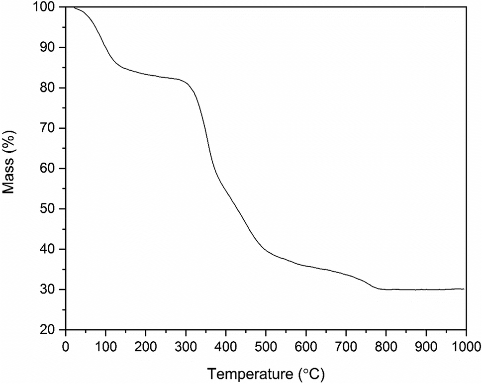 | ||
| Fig. 5 Thermogravimetric curve of the as-electroblown ZrO2/PVP composite fibers in air (80 mol%) and N2 (20 mol%, the purge gas). | ||
3.3. Crystal structure of the ZrO2 fibers
X-ray diffraction patterns of the zirconium dioxide fibers calcined at different temperatures in air for six hours are shown in Fig. 6. The relative amounts of different crystalline phases and mean crystallite sizes of the fibers calcined at 500, 600, 700 and 800 °C are listed in Table 1. From the X-ray diffractograms it may be noticed that the structure of the fibers transforms from amorphous to the tetragonal between 400 and 500 °C and gradually from the tetragonal to the monoclinic between 500 and 800 °C. The same kind of crystallization behaviour has also been observed in previous studies on zirconium dioxide nano- and microfibers.22,25–27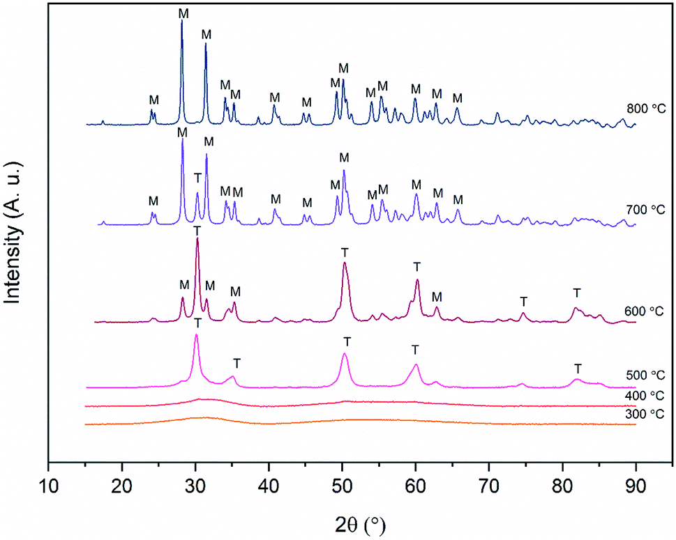 | ||
| Fig. 6 X-ray diffractograms of ZrO2 fibers calcined at different temperatures for 6 hours. T and M denote tetragonal and monoclinic crystalline phases respectively. | ||
| Calc. T | T/M ratio (wt%) | App. cryst. size T/M (nm) |
|---|---|---|
| 500 °C | 89/11 | 9/13 |
| 600 °C | 61/39 | 26/26 |
| 700 °C | 15/85 | 29/40 |
| 800 °C | 0/100 | —/63 |
It is seen from Table 1 that the crystallite size of the fibers increases due to sintering as the calcination temperature is increased. The large crystallites of around 60 nm in the fibers calcined at 800 °C are clearly observable by FESEM (Fig. 3D). It is also evident that as the temperature and crystallite size increase, the relative proportion of the monoclinic phase increases. The tetragonal phase is predominant up to a calcination temperature of 600 °C. After calcination at this temperature, the average crystallite size of both the tetragonal and monoclinic phase is 26 nm. After calcination at 700 °C, the majority of the crystals are 40 nm in size and have the monoclinic phase. Only a minor portion of the crystals are in the tetragonal phase and their size hasn't increased much compared to the fibers calcined at 600 °C. The results are well supported by the theory of Garvie46,47 who estimated the critical crystallite size for the stabilization of the tetragonal zirconia to be approximately 30 nm. Garvie suggested that owing to the lower surface free energy of the tetragonal ZrO2 and lower bulk free energy of the monoclinic ZrO2, the tetragonal crystallites are stabilized when they are small enough to provide a large enough surface area to counteract the higher bulk free energy.
3.4. Specific surface area, pore size and pore volume analysis of the ZrO2 fibers
Specific surface area of the ZrO2 fibers was analysed by the Brunauer–Emmett–Teller (BET) method, and the pore size and volume of the fibers were analysed by the Barrett–Joyner–Halenda (BJH) method using nitrogen gas adsorption and desorption in both analyses. Prior to the analyses, the samples were ground in order to better correspond to the conditions in the adsorption experiments. Both amorphous and tetragonal as well as monoclinic ZrO2 were analysed, calcined at 400, 500 and 800 °C, respectively. The results are presented in Table 2. From the results it can be observed that the fibers calcined at 500 °C have the greatest surface area and pore volume. The fibers calcined at 400 °C have the smallest surface area and pore volume.| Calc. T | BET surface area | BJH pore volume | BJH av. pore diameter |
|---|---|---|---|
| 400 °C | 0.93 m2 g−1 | 0.0044 cm3 g−1 | 15 nm |
| 500 °C | 14 m2 g−1 | 0.0184 cm3 g−1 | 4.1 nm |
| 800 °C | 1.7 m2 g−1 | 0.0179 cm3 g−1 | 15 nm |
3.5. Surface analysis of the ZrO2 fibers by X-ray photoelectron spectroscopy (XPS)
In order to examine the chemical composition of the ZrO2 fiber surfaces both before and after adsorption of Sb(V) an X-ray photoelectron spectroscopy analysis was performed. Fibers calcined at 400 °C were analysed before and fibers calcined at 500 °C were analysed after the adsorption of Sb(V). Survey spectra of the fibers are shown in Fig. S4.† The detected elements were Zr, Sb, O and C. Contents of the elements and different bonding environments of O and C atoms are presented in Table S1.† The fibers proved to be quite pure as the only contaminant was carbon. Except for the carbon from ambient air minor amounts of residual carbon from the polymer were detected (denoted atypical carbon in Fig. 7). This is in line with the TG analysis of the as-electroblown ZrO2/PVP composite fibers, that revealed the total removal of the polymer not to be complete until at 750 °C (Fig. 5). All the Zr atoms had an oxidation state of +4 and all the Sb atoms an oxidation state of +5. A major part of the oxygen signal originated from adsorbed hydroxyl groups and water, 70 mol% and 50 mol% for the fibers analysed before and after adsorption of Sb(V) respectively.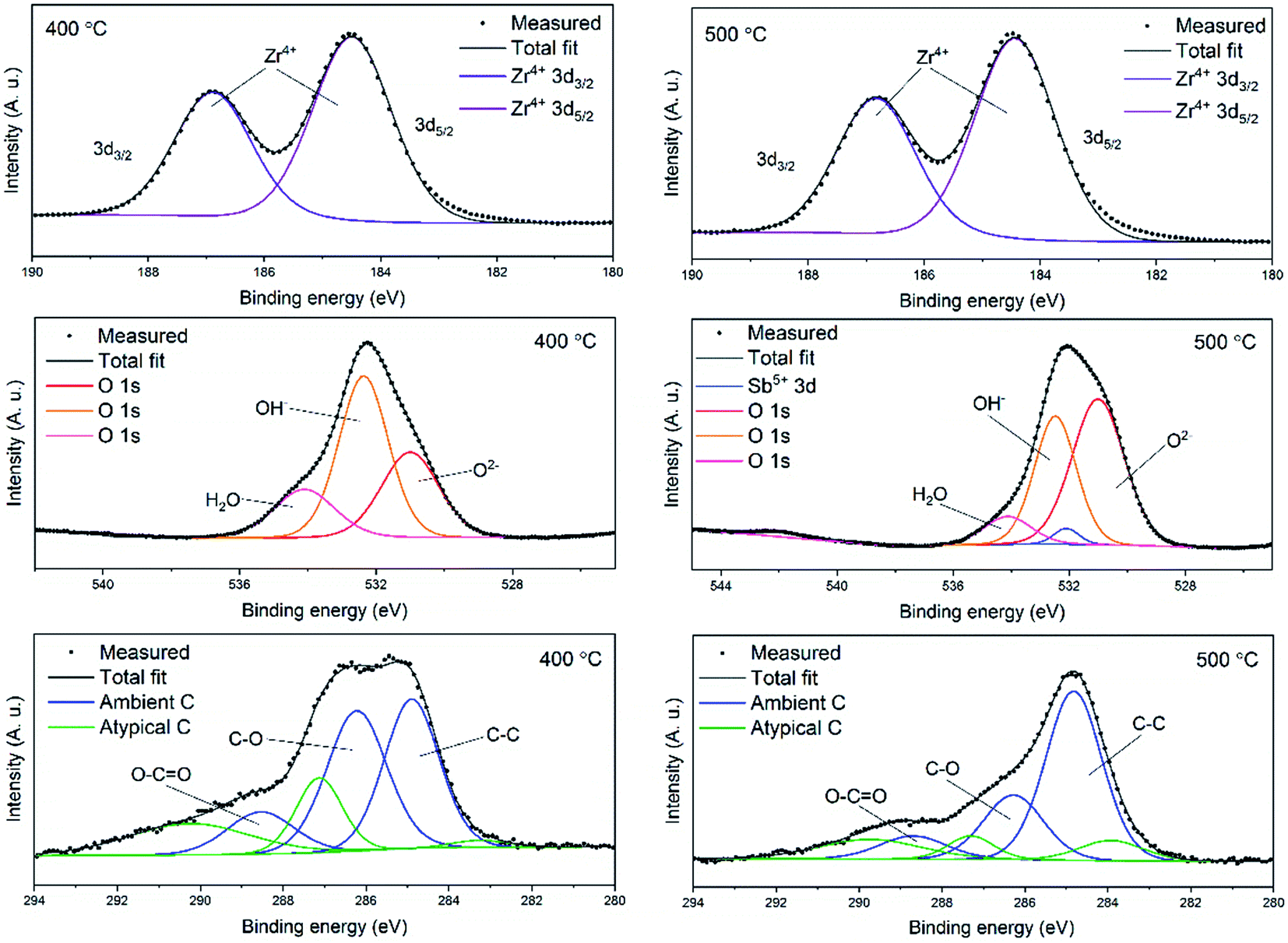 | ||
| Fig. 7 High resolution X-ray photoelectron spectra of ZrO2 fibers before (calcination 400 °C) and after (calcination 500 °C) adsorption of Sb(V). | ||
3.6. Adsorption properties of the ZrO2 fibers
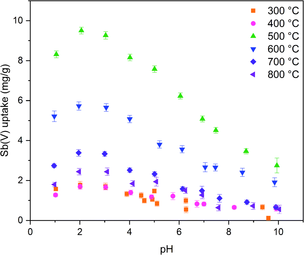
The calcination temperature is known to have a major impact on adsorption properties of a material through crystal structure transformations, morphology and chemical composition. Therefore, the effect of calcination temperature on Sb(V) adsorption by ZrO2 fibers was studied. The pH affects both speciation of Sb(V) and properties of the adsorbent. The optimal uptake pH can be found in an area where the charges of the adsorbing Sb(V) species and the adsorbent surface are the opposite. The zeta potential measurement showed that the surface charges of all the fibers are positive from the most acidic sample to their point of zero charges (pHPZC), Fig. 8. Estimated pHPZC values are 5.3, 6.4, 6.8, 6.8, 6.8 and 6.9 in order of increasing calcination temperature of the fibers. The pHPZC of the fibers calcined at 300 °C is clearly and pHPZC of the fibers calcined at 400 °C is slightly lower than those of the rest of the fibers. This could be attributed to a higher amount of polymer residues in the fibers calcined at lower temperatures. According to the Sb(V) uptake results (Fig. 9), the optimum pH for adsorption is between 2 and 3 for all the synthesized fibers since in this pH range the surface charge of the fibers is highly positive and Sb(OH)6− becomes increasingly prevalent over the neutral Sb(OH)5 species. Based on density functional theory (DFT) calculations, Sb(OH)6− adsorbs on tetragonal and monoclinic ZrO2 (111) planes by oxygen atoms of Sb(OH)6− binding with Zr atoms.19 Two oxygen atoms bind with one Zr atom on the tetragonal ZrO2 (111) plane and three oxygen atoms bind with three Zr atoms on the monoclinic ZrO2 (111) plane. At the higher pH values larger concentration of competing OH− ions probably hampers the adsorption of Sb(OH)6− by creating negative surface charge on the fibers.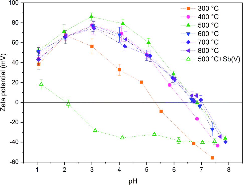 | ||
| Fig. 8 Zeta potentials of 0.5 g L−1 ZrO2 fibers calcined at 300 to 800 °C in 0.01 M NaNO3 as a function of pH and zeta potential of ZrO2 fibers calcined at 500 °C after adsorption of Sb(V) in 10 mg L−1 Sb(V) in 0.01 M NaNO3 solution. | ||
 | ||
| Fig. 9 Sb(V) uptake capacities of ZrO2 fibers calcined at 300 to 800 °C as a function of pH with 10 mg L−1 Sb(V) in 0.01 M NaNO3 (0.5 g L−1 ZrO2). | ||
Zeta potential of the fibers calcined at 500 °C decreases after adsorption of Sb(V) in the studied pH range and pHPZC drops from 6.8 to approximately 2.0, Fig. 8. Several studies have suggested that the decrease of the adsorbent's zeta potential after adsorption of anions is related to an inner-sphere complexation in which chemical bond is formed between Sb(OH)6− and adsorbent surface.18,48,49 In contrast, an outer-sphere complexation reaction is based on physical interaction between the anion and positively charged adsorbent surface and does not change the surface charge of the adsorbent. Our results show that the zeta potential decreases drastically after Sb(V) adsorption indicating an inner-sphere complexation reaction. Adsorption is most efficient in the pH range where charges of the adsorbent and adsorbate are opposite implying that adsorption is most probably initiated by electrostatic attraction. However, the possibility of adsorption partly occurring by outer-sphere complexation cannot be excluded.
The fibers calcined at 500 °C show the highest adsorption capacity throughout the studied pH range. At this calcination temperature, the tetragonal crystal structure is formed. Below 500 °C, the fibers remain amorphous, and when the temperature is raised further, the monoclinic structure becomes increasingly prevalent (Table 1). Hence, it is probable that the tetragonal crystal structure has a significant impact on the adsorption since the adsorption capacity of the fibers decreases along with the amount of the tetragonal phase. Similarly, Luo et al. observed that a high tetragonal to monoclinic ratio of ZrO2 was associated with a large Sb(V) adsorption capacity when compared to lower ratios.19 They suggested this to stem from a higher adsorption energy of Sb(V) onto the tetragonal than the monoclinic ZrO2 and hence a more stable adsorption. Moreover, as already seen (Tables 1 and 2), the calcination process leads to the crystallite growth and densification of the structure and thereby a decrease in the specific surface area. The densification is probably also destroying sites taking part in the Sb(V) adsorption by crystal defect removal. Thus, it is possible that the crystal structure transformation and crystallite growth, which is decreasing the specific surface area, have a combined effect on lowering the adsorption capacity when the fibers are calcined above 500 °C. As regards the fibers calcined at 300 and 400 °C, the amorphous structure, a small specific surface area, low porosity and possible polymer residues blocking the fiber surfaces are likely to weaken the adsorption properties. The tetragonal structure, large surface area and higher porosity evidently enhance the Sb(V) adsorption properties of the ZrO2 fibers calcined at 500 °C.
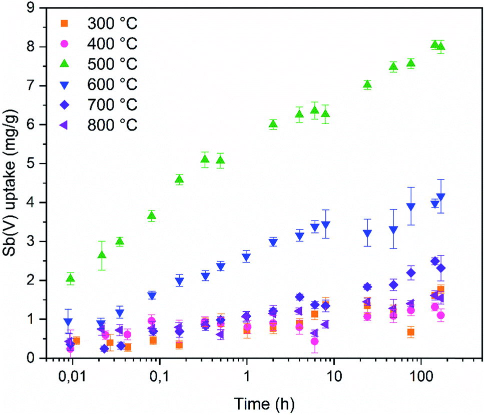
Fast adsorption kinetics is essential for purification of high volumes of water. To assess if the ZrO2 fibers are fast enough to be used in real processes the adsorption kinetics was studied (Fig. 10). The tetragonal ZrO2 fibers calcined at 500 °C reach 30% of 7 days' uptake in only one minute. The one minute Sb(V) uptake percentage of the other fibers ranges from 10 to 40% but higher Sb(V) adsorption capacity (in mg g−1) of the tetragonal ZrO2 fibers calcined at 500 °C makes them superior compared to the other fibers. The amount of Sb(V) adsorbed by the fibers follows the proportion of the tetragonal crystal structure in the fibers, as seen from Fig. 9. As revealed by Fig. 10, there are no noticeable differences in the Sb(V) uptake capacities between the amorphous (calcination 300 and 400 °C) and completely monoclinic (calcination 800 °C) ZrO2 fibers. However, an interesting difference was observed between the fibers calcined at the lowest and highest temperatures. Regardless of the calcination temperature, the pH began to decrease from 7 at the moment the solution was brought into contact with the fibers. The decrease in pH was the greatest for the fibers calcined at 300 °C (pHeq 4.4) and the smallest for the fibers calcined at 600 to 800 °C (pHeq 6.3). For the fibers calcined at 400 and 500 °C the equilibrium pH was 6.0.
 | ||
| Fig. 10 Sb(V) uptake capacities of ZrO2 fibers calcined at 300 to 800 °C as a function of time with initial 10 mg L−1 Sb(V) in 0.01 M NaNO3. | ||
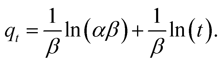
Three different kinetic models, described below, were fitted to the kinetic data in their non-linear forms. The pseudo-first-order (PFO) model was introduced by Lagergren in 1898 to describe adsorption of oxalic and malonic acid onto charcoal from the liquid phase. The kinetics is thought to be limited by an intra-particle diffusion and usually fits the data best at high initial concentrations.50,51 The PFO eqn (2) is written in the form
| qt = qeq(1 − e−K1t) | (2) |
The pseudo-second-order model (PSO) assumes that the rate is limited by a chemical reaction that involves sharing or exchange of electrons between the adsorbent and adsorbate. The adsorption rate is unaffected by a reverse reaction and the model works particularly well at low concentrations. The PSO model (3) is expressed in the form
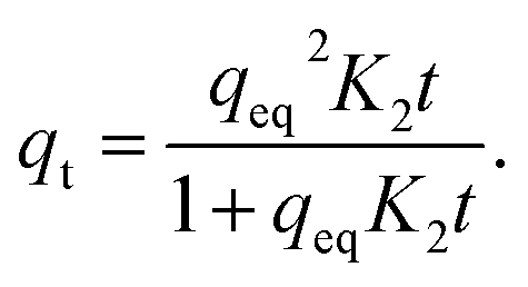 | (3) |
The Elovich eqn (4) was presented by Zeldowitsch to describe the chemisorption rate of carbon monoxide on manganese dioxide. The rate of adsorption decreases exponentially with an increase in the adsorbed gas. Although the model was developed for gas adsorption, in recent years, the Elovich equation has been used to describe adsorption of different ions from aqueous systems by heterogeneous adsorbents.51
 | (4) |
In eqn (4)α (mg g−1 h−1) is the initial adsorption rate, and β (g mg−1) is the desorption constant.51
The goodness of the fit was assessed by the coefficient of determination (R2) (Table 3) and residual analysis (Fig. S5†). According to these analyses, the Elovich model fits the kinetic data the best and the pseudo-second-order the second best meaning that adsorption kinetics in the studied time range follow logarithmic model.
| Calc. T | PFO | PSO | Elovich | ||||||
|---|---|---|---|---|---|---|---|---|---|
| K 1 (h−1) | q eq (mg g−1) | R 2 | K 2 (g mg h−1) | q eq (mg g−1) | R 2 | α (mg g−1 h−1) | β (g mg−1) | R 2 | |
| 300 °C | 3.4 | 1.2 | 0.578 | 2.8 | 1.3 | 0.673 | 61 | 7.0 | 0.859 |
| 400 °C | 28.2 | 1.0 | 0.668 | 34.9 | 1.1 | 0.741 | 8040 | 13.4 | 0.785 |
| 500 °C | 11.5 | 6.6 | 0.720 | 2.4 | 6.9 | 0.843 | 4072 | 1.7 | 0.978 |
| 600 °C | 4.8 | 3.4 | 0.733 | 2.1 | 3.5 | 0.853 | 521 | 2.9 | 0.976 |
| 700 °C | 1.4 | 1.9 | 0.729 | 0.9 | 2.0 | 0.814 | 36 | 4.5 | 0.964 |
| 800 °C | 31.5 | 1.2 | 0.373 | 22.9 | 1.2 | 0.538 | 1517 | 9.5 | 0.899 |
The highest PFO K1 values are observed for fibers calcined at 400, 500 and 800 °C. Similar to PFO model, PSO model's K2 values belonging to fibers calcined at 400 and 800 °C are the highest. However, the third highest value is observed for fibers calcined at 300 °C instead of 500 °C. The qeq values of PFO and PSO models are close to each other but the models seem to systematically underestimate the experimental equilibrium values due to poor correlation with the data. With the Elovich equation the highest adsorption constants are observed for fibers calcined at 400, 500 and 800 °C and highest desorption constants for fibers calcined at 300, 400 and 800 °C.
Isotherm experiment was conducted for fibers calcined at 300 to 800 °C to determine the effect of calcination temperature on adsorption capacity. In the studied equilibrium concentration area, the tetragonal fibers calcined at 500 °C achieve the highest adsorption capacity, Fig. 11. This was expected since the same fibers had the highest uptake in the pH effect experiments due to its tetragonal structure and the largest surface area. The large surface area enables the highest capacity by offering more adsorption sites for antimony as repulsion between adsorbed and solute Sb(OH)6− interferes further adsorption. Based on the EDX mapping results (Fig. S3†) the whole fiber length is taking part in adsorption maximizing the capacity by decreasing repulsion between adsorbed and solute Sb(OH)6−. The second highest capacity is observed for fibers with the second highest portion of tetragonal crystallites (calcination 600 °C) and correspondingly the third highest capacity, with a small margin, for fibers with the third highest portion of tetragonal crystallites (calcination 700 °C). For fibers calcined at 300, 400 and 800 °C the experimental adsorption capacity is almost the same. Based on the values at the last data point the maximum capacities in the calcination temperature order are 3.2, 2.9, 8.6, 5.4, 3.4 and 2.5 mg g−1. Higher values could be achieved in the optimal pH range from 2 to 3. However, the obtained adsorption capacities are in the same order of magnitude as those of inorganic adsorbents for Sb(V) such as 0.556 mg g−1 for bentonite at pH 6,54 1.27 mg g−1 for goethite at pH 6.0 (ref. 55) and 8.6 mg g−1 for TiO2 nanoparticles at pH 2.2.56 Even higher adsorption capacities have been achieved with highly porous or high surface area products such as 60.4 mg g−1 for Fe–Zr bimetal oxide18 at pH 7.0, 57.2 mg g−1 for zirconium oxide carbon nanofibers19 at pH 7.0 and 18.5 mg g−1 for ferric hydroxide18 at pH 7.0. The experimental data was evaluated using Freundlich (eq. (5)) and Langmuir (eq. (6)) isotherm models.52,53
| qeq = kFceq1/n. | (5) |
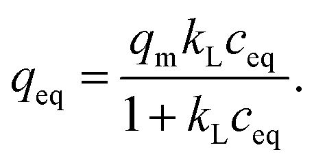 | (6) |
 | ||
| Fig. 11 Sb(V) adsorption isotherms for ZrO2 fibers calcined at 300 to 800 °C after 24 h. Initial Sb(V) concentration was 1 to 25 mg L−1 in 0.01 M NaNO3 at pH 6.0. | ||
| Calc. T | Freundlich | Langmuir | ||||
|---|---|---|---|---|---|---|
| k F (mg1−(1/n) L1/n g−1) | n | R 2 | q m (mg g−1) | k L (L mg−1) | R 2 | |
| 300 °C | 0.39 | 1.5 | 0.970 | 6.4 | 0.040 | 0.936 |
| 400 °C | 0.49 | 1.7 | 0.944 | 4.9 | 0.068 | 0.932 |
| 500 °C | 4.6 | 5.0 | 0.981 | 7.2 | 3.1 | 0.746 |
| 600 °C | 2.3 | 3.9 | 0.972 | 4.7 | 0.88 | 0.698 |
| 700 °C | 1.1 | 2.9 | 0.949 | 3.3 | 0.33 | 0.756 |
| 800 °C | 0.69 | 2.6 | 0.907 | 2.6 | 0.22 | 0.747 |
Based on the R2 values and residual analysis Freundlich model (R2 0.907–0.981) describes isotherm data better than Langmuir model (R2 0.698–0.936) with all fibers (Fig. S6†). This indicates that adsorption would occur as multilayer adsorption on heterogeneous sites rather than approaching full monolayer coverage. Due to a low correlation with Langmuir model, maximum monolayer capacities (qm) are significantly different from experimental values. Model seems to overestimate maximum capacities of fibers calcined at 300 and 400 °C but then again model underestimates the maximum capacities of fibers calcined at 500 and 600 °C. However, model succeeds to evaluate capacities of fibers calcined at 700 and 800 °C that experimental values are close to Langmuir monolayer capacities.
Reusability of ZrO2 fibers calcined at 500 and 600 °C, which had the highest capacities in the isotherm experiment, was studied for five adsorption/desorption cycles using 1 M NaOH as a desorption agent due to a good regeneration performance of NaOH in the literature.49,57,58 The initial Sb(V) uptakes of the fibers calcined at 500 °C and 600 °C are 6.2 mg g−1 and 3.9 mg g−1, respectively. In the second cycle, the uptake dropped to 54% and 52% of the first cycle's values, respectively, and on the last cycle uptake of both materials was 40% of the initial uptake. Thus, the decrease in the uptake of these two materials is rather similar despite their different capacities and structure. The fact that the material is only partially regenerable is probably due to the different adsorption sites: strong chemical sites (inner-sphere complexes) and weak physical sites (outer-sphere complexes). Elution of chemically bound Sb(V) is difficult but regeneration of the weak sites is possible with OH− which is observed also for La-doped magnetic biochars57 and Mg/Al layered double hydroxide.58 The regeneration ability of NaOH from the weak adsorption sites bases on deprotonation of the material surface which is leading to electrostatic repulsion between negatively charged surface and Sb(OH)6−.58 Due to a reasonable regenerability of the fibers, the reuse of the materials is possible with some compromise in the adsorption capacity (Fig. 12).
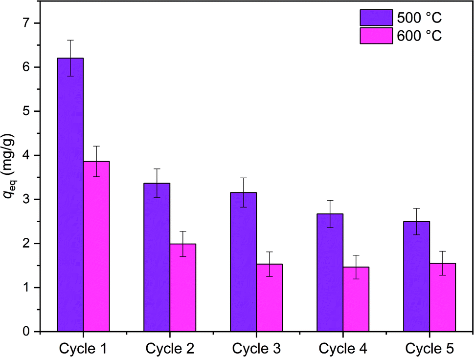 | ||
| Fig. 12 The Sb(V) uptake of the fibers calcined at 500 °C and 600 °C in five adsorption/desorption cycles. In the adsorption cycle 0.5 g L−1 of ZrO2 fibers is loaded with 10 mg L−1 in 0.01 M NaNO3 at pH 6.0 for 18 h and regenerated with 1 M NaOH for 6 h between adsorption cycles. | ||
4. Conclusions
For removal of Sb(V) from industrial waste water, we have synthesized ZrO2 fibers with an average diameter of 570 to 720 nm. The fibers were prepared by electroblowing and calcination of the as-electroblown fibers. The throughput of the fiber preparation was considerably improved compared to electrospinning. The calcination temperature affects both the morphology and crystallinity of the fibers. Up to a calcination temperature of 500 °C the fibers are smooth and their structure transforms from amorphous to the tetragonal between 400 and 500 °C. The fibers coarsen and the amount of the monoclinic phase increases at the higher calcination temperatures. The fibers turn completely to the monoclinic between 700 and 800 °C. Moreover, the size of the crystallites in the fibers increases with increasing calcination temperature due to sintering which is lowering the specific surface area.The effect of the crystal structure of the ZrO2 fibers on Sb(V) adsorption was investigated. The fibers with the largest proportion of the tetragonal crystal phase, calcined at 500 °C, have the highest Sb(V) uptake throughout the studied pH range and the highest adsorption capacity in the isotherm experiment. The uptake decreases with decreasing proportion of the tetragonal phase in the fibers. In the amorphous ZrO2 fibers the low Sb(V) uptake capacity is possibly due to the lack of the tetragonal crystallites and presence of residual polymer that might be blocking the surface of the fibers. The adsorption kinetics of all the synthesized fibers is fast. However, the highest adsorption capacity of the fibers calcined at 500 °C makes them most promising for Sb(V) separation. The superiority of this material is probably due to the tetragonal crystal structure, a large specific surface area and high porosity. In the zeta potential experiment the pHPZC of these fibers declined drastically after adsorption of Sb(V) indicating an inner sphere complexation reaction. However, in the reusability test some of the adsorption sites were regenerable also indicating a presence of a weaker outer sphere complex formation which enables the reuse of the material. Due to their ease of preparation and small size, the submicron ZrO2 fibers have potential for a novel, efficient and sustainable adsorbent for various industrial applications.
Conflicts of interest
There are no conflicts of interest to declare.Acknowledgements
J. Paajanen and S. Lönnrot thank Fortum Power and Heat Oy for financial support for the research.References
- M. Filella, N. Belzile and Y.-W. Chen, Earth-Sci. Rev., 2002, 57, 125 CrossRef CAS.
- K. Klochko, U.S. Geological Survey 2016 Minerals Yearbook, Antimony (Advance Release), https://minerals.usgs.gov/minerals/pubs/commodity/antimony/, accessed April 2019 Search PubMed.
- Council of The European Union, Council directive 98/83/EC of 3 November 1998 on the quality of water intended for human consumption, 1998, https://eur-lex.europa.eu/legal-content/EN/ALL/?uri=CELEX%3A31998L0083, accessed April 2019.
- United States Environmental Protection Agency (US EPA), National primary drinking water regulations, https://www.epa.gov/ground-water-and-drinking-water/national-primary-drinking-water-regulations, accessed April 2019.
- Nuclear Energy Agency, Radiation protection aspects of primary water chemistry and source-term management, Radiological Protection NEA/CRPPH/R(2014)2, http://www.oecd-nea.org, accessed September 2019.
- R. Harjula, E. Tusa and R. Kvarnstrom, Removal of Antimony-124 from PWR Coolant Water, presented in part at 2009 Waste Management Symposium – WM2009/WM'09, Phoenix, Arizona, United States, March, 2009 Search PubMed.
- R. Harjula, E. Tusa, M. Pehkonen and R. Kvarnstrom, Development and Testing of New Antimony Selective Media, presented in part at Annual Radioactive Waste Management Symposium 2011, Phoenix, Arizona, United States, February and March, 2011 Search PubMed.
- Y.-A. Lin, S.-J. Jiang and A. C. Sahayam, Food Chem., 2017, 230, 76 CrossRef CAS PubMed.
- N. Takeno, Atlas of Eh-pH diagrams, Intercomparison of thermodynamic databases, Geological Survey of Japan Open File Report No. 419, National Institute of Advanced Industrial Science and Technology, Research Center for Deep Geological Environments, 2005, https://www.gsj.jp/data/openfile/no0419/openfile419e.pdf, accessed April 2019 Search PubMed.
- M. Filella, N. Belzile and Y.-W. Chen, Earth-Sci. Rev., 2002, 59, 265 CrossRef CAS.
- M. M. Al-Ne'aimi and M. M. Al-Khuder, Spectrochim. Acta, Part A, 2013, 105, 365 CrossRef PubMed.
- G. Ungureanu, S. Santos, R. Boaventura and C. Botelho, J. Environ. Manage., 2015, 151, 326 CrossRef CAS PubMed.
- Z. A. AL-Othman, R. Ali and M. Naushad, Chem. Eng. J., 2012, 184, 238 CrossRef CAS.
- A. A. Alqadami, M. Naushad, M. A. Abdalla, T. Ahamad, Z. A. ALOthman, S. M. Alshehri and A. A. Ghfar, J. Cleaner Prod., 2017, 156, 426 CrossRef.
- K. Deepa, C. Prasad, N. V. V. Jyothi, M. Naushad, S. Rajendran, S. Karlapudi and S. H. Kumar, Desalin. Water Treat., 2018, 111, 278 CrossRef CAS.
- A. A. Alqadami, M. Naushad, Z. A. Alothman and A. A. Ghfar, ACS Appl. Mater. Interfaces, 2017, 9, 36026 CrossRef CAS PubMed.
- S. Lönnrot, V. Suorsa, J. Paajanen, T. Hatanpää, M. Ritala and R. Koivula, RSC Adv., 2019, 9, 22355 RSC.
- X. Li, X. Dou and J. Li, J. Environ. Sci., 2012, 24(7), 1197 CrossRef CAS.
- J. Luo, X. Luo, J. Crittenden, J. Qu, Y. Bai, Y. Peng and J. Li, Environ. Sci. Technol., 2015, 49, 11115 CrossRef CAS PubMed.
- Y. M. Shin, M. M. Hohman, M. P. Brenner and G. C. Rutledge, Polymer, 2001, 42, 9955 CrossRef CAS.
- S. Thenmozhi, N. Dharmaraj, K. Kadirvelu and H. Y. Kim, Mater. Sci. Eng., B, 2017, 217, 36 CrossRef CAS.
- J. Li, H.-Y. Qi and Y.-P. Shi, Anal. Chim. Acta, 2009, 651, 182 CrossRef CAS PubMed.
- H. Wang, Y. Duan and W. Zhong, ACS Appl. Mater. Interfaces, 2015, 7, 26414 CrossRef CAS PubMed.
- Y. Chen, X. Mao, H. Shan, J. Yang, H. Wang, S. Chen, F. Tian, J. Yu and B. Ding, RSC Adv., 2014, 4, 2756 RSC.
- R. Ruiz-Rosas, J. Bedia, J. M. Rosas, M. Lallave, I. G. Loscertales, J. Rodriguez-Mirasol and T. Cordero, Catal. Today, 2012, 187, 77 CrossRef CAS.
- E. Davies, A. Lowe, M. Sterns, K. Fujihara and S. Ramakrishna, J. Am. Ceram. Soc., 2008, 91, 1115 CrossRef CAS.
- Y. Zhao, Y. Tang, Y. Guo and X. Bao, Fibers Polym., 2010, 11, 1119 CrossRef CAS.
- E. Formo, M. S. Yavuz, E. P. Lee, L. Lane and Y. Xia, J. Mater. Chem., 2009, 19, 3878 RSC.
- V. G. Maksimov and N. M. Varrik, Glass Ceram., 2017, 74, 288 CrossRef CAS.
- M. Wang, X. Chen, H. Wang, H. Wu, X. Jin and C. Huang, J. Mater. Chem. A, 2017, 5, 311 RSC.
- B. Cheng, X. Tao, L. Shi, G. Yan and X. Zhuang, Ceram. Int., 2014, 40, 15013 CrossRef CAS.
- S. Ramakrishna, K. Fujihara, W.-E. Teo, T.-C. Lim and Z. Ma, An Introduction to Electrospinning and Nanofibers, World Scientific Publishing Co. Pte. Ltd., Singapore, 2005 Search PubMed.
- Elmarco, Supplier of industrial level and lab scale electrospinning machine, https://elmarco.com/, accessed April 2019.
- Fanavaran Nano-Meghyas (Fnm co. Ltd.), Supplier of industrial level and lab scale electrospinning machine and accessories, http://en.fnm.ir/, accessed April 2019.
- J. L. Daristotle, A. M. Behrens, A. D. Sandler and P. Kofinas, ACS Appl. Mater. Interfaces, 2016, 8, 34951 CrossRef CAS PubMed.
- E. S. Medeiros, G. M. Glenn, A. P. Klamczynski, W. J. Orts and L. H. C. Mattoso, J. Appl. Polym. Sci., 2009, 113, 2322 CrossRef CAS.
- W. Tutak, S. Sarkar, S. Lin-Gibson, T. M. Farooque, G. Jyotsnendu, D. Wang, J. Kohn, D. Bolikal and C. G. Simon Jr, Biomaterials, 2013, 34, 2389 CrossRef CAS PubMed.
- Y. Polat, E. S. Pampal, E. Stojanovska, R. Simsek, A. Hassanin, A. Kilic, A. Demir and S. Yilmaz, J. Appl. Polym. Sci., 2016, 133, 43025 CrossRef.
- I. C. Um, D. Fang, B. S. Hsiao, A. Okamoto and B. Chu, Biomacromolecules, 2004, 5, 1428 CrossRef CAS PubMed.
- P. L. Soti, K. Bocz, H. Pataki, Z. Eke, A. Farkas, G. Verreck, E. Kiss, P. Fekete, T. Vigh, I. Wagner, Z. K. Nagy and G. Marosi, Int. J. Pharm., 2015, 494, 23 CrossRef CAS PubMed.
- B. Demuth, D. L. Galata, E. Szabo, B. Nagy, A. Farkas, A. Balogh, E. Hirsch, H. Pataki, Z. Rapi, L. Bezur, T. Vigh, G. Verreck, Z. Szalay, A. Demeter, G. Marosi and Z. K. Nagy, Mol. Pharmaceutics, 2017, 14, 3927 CrossRef CAS PubMed.
- D. Tang, X. Zhuang, C. Zhang, B. Cheng and X. Li, J. Appl. Polym. Sci., 2015, 132, 42326 Search PubMed.
- J. Holopainen and M. Ritala, J. Eur. Ceram. Soc., 2016, 36, 3219 CrossRef CAS.
- L. Lutterotti, D. Chateigner, S. Ferrari and J. Ricote, Thin Solid Films, 2004, 450, 34 CrossRef CAS.
- E. Santala, R. Koivula, R. Harjula and M. Ritala, Environ. Technol., 2018, 1 CrossRef PubMed.
- R. C. Garvie, J. Phys. Chem., 1965, 69, 1238 CrossRef CAS.
- R. C. Garvie and M. F. Goss, J. Mater. Sci., 1986, 21, 1253 CrossRef CAS.
- M. E. Essington and M. A. Stewart, Soil Sci. Soc. Am. J., 2016, 80, 1197 CrossRef CAS.
- K. Yang, J. Zhou, Z. Lou, X. Zhou, Y. Liu, Y. Li, S. A. Baig and X. Xu, Chem. Eng. J., 2018, 354, 577 CrossRef CAS.
- Y. S. Ho and G. McKay, Process Biochem., 1999, 34, 451 CrossRef CAS.
- Y.-S. Ho, J. Hazard. Mater., 2006, 136, 681 CrossRef CAS PubMed.
- M. Kostić, M. Radović, N. Velinov, S. Najdanović, D. Bojić, A. Hurt and A. Bojić, Ecotoxicol. Environ. Saf., 2018, 159, 332 CrossRef PubMed.
- M. Kostić, M. Đorđević, J. Mitrović, N. Velinov, D. Bojić, M. Antonijević and A. Bojić, Environ. Sci. Pollut. Res., 2017, 24, 17790 CrossRef PubMed.
- J. Xi, M. He and C. Lin, Microchem. J., 2011, 97, 85 CrossRef CAS.
- J. Xi and M. He, Water Qual. Res. J. Can., 2013, 48, 223 CrossRef CAS.
- T. Zhao, Z. Tang, X. Zhao, H. Zhang, J. Wang, F. Wu, J. P. Giesy and J. Shi, Environ. Sci.: Nano, 2019, 6, 834 RSC.
- L. Wang, J. Wang, Z. Wang, C. He, W. Lyu, W. Yan and L. Yang, Chem. Eng. J., 2018, 354, 623 CrossRef CAS.
- S.-H. Lee, M. Tanaka, Y. Takahashi and K.-W. Kim, Chemosphere, 2018, 211, 903 CrossRef CAS PubMed.
Footnotes |
| † Electronic supplementary information (ESI) available. See DOI: 10.1039/c9na00414a |
| ‡ These authors contributed equally to the work. |
| This journal is © The Royal Society of Chemistry 2019 |