
 Open Access Article
 This Open Access Article is licensed under a Creative Commons Attribution-Non Commercial 3.0 Unported Licence
Enhanced chemical and physical properties of PEDOT doped with anionic polyelectrolytes prepared from acrylic derivatives and application to nanogenerators†
Eui Jin
Ko
 a,
Jisu
Hong
b,
Chan Eon
Park
*b and
Doo Kyung
Moon
*a
a,
Jisu
Hong
b,
Chan Eon
Park
*b and
Doo Kyung
Moon
*a
aNano and Information Materials (NIMs) Lab., Department of Chemical Engineering, College of Engineering, Konkuk University, 1 Hwayang-dong, Gwangjin-gu, Seoul 05029, Republic of Korea. E-mail: dkmoon@konkuk.ac.kr
bDepartment of Chemical Engineering, Pohang University of Science and Technology (POSTECH), Pohang 790-784, Republic of Korea. E-mail: cep@postech.ac.kr
First published on 16th September 2019
Abstract
Acrylic monomers, 4-hydroxybutyl acrylate (HBA) and 2-carboxyethyl acrylate (CEA), were each co-polymerized with styrene sulfonate in 10 mol% ratio to synthesize two types of anionic polyelectrolytes, P(SS-co-HBA) and P(SS-co-CEA), respectively. Through oxidative polymerization, two types of PEDOT composites (PEDOT:P(SS-co-HBA) and PEDOT:P(SS-co-CEA)) were synthesized, to which the anionic templates were applied as dopants. The composites were similar to PEDOT:PSS; however, crosslinking occurred with an increase in annealing temperature after film casting, which increased the electrical conductivity and hydrophobicity. The composites were applied as electrodes to PVDF-based piezoelectric nanogenerators (PNGs) having an electrode/PVDF/electrode structure. The output voltage, current, and maximum output power of PNG-2D(60) (PEDOT:P(SS-co-HBA)) annealed at a mild temperature (60 °C) were 4.12 V, 817.3 nA, and 847.5 nW, respectively, while those of PNG-3D(60) (PEDOT:P(SS-co-CEA)) annealed at 60 °C were 3.75 V, 756.5 nA, and 716.9 nW, respectively. Thus, the composites showed 13.4% and 11.3% improvements in the maximum output power compared with that of PNG-2D & 3D(RT) dried at room temperature, respectively. These results indicated 27.4% and 7.8% improvements, respectively, compared with PNG-1D(60) in which PEDOT:PSS without any crosslinking effect was applied. The PNGs demonstrated high potential as power sources owing to their sensitivity and excellent charging voltage performance for a 1 μF capacitor.
Introduction
“Smart factory” and “Industry 4.0” are opening a new industrial era. In particular, due to the rapid growth of the internet of things technology, small electronics such as sensors, actuators, mobiles, and wearable electronics are studied as biomedical devices, health monitoring systems, wireless transmission, etc. These devices can be operated at a low power and require a mobile and sustainable power source; therefore, the development of self-powered nanogenerator technology is crucial.1–10 Such a low-powered energy conversion and harvesting system converts natural energy into electrical energy. Among these systems, the piezoelectric technology, which uses mechanical energy such as human motions, wind flow, vibration, etc. as its energy source, is one of the best next-generation technologies because it is eco-friendly.11–13For this reason, extensive research is conducted on active materials and electrodes. Inorganic piezoelectric materials with a high piezoelectric coefficient such as lead zirconate-titanate (PZT) and barium titanate (BaTiO3) are representative active materials. Although they are inherently rigid, brittle and poorly biocompatible, they show excellent performances. To overcome this problem, Lee et al. reported high-performance piezoelectric nanogenerators (PNGs) by developing chemically reinforced composites using amine-functionalized PZT nanoparticles and a thermoplastic triblock copolymer grafted with maleic anhydride.14 Liu et al. reported a high piezoelectric performance by developing lead-free (Na0.5Bi0.5)TiO3–BaTiO3 using a sol–gel based electrospinning method.13 Despite these improvements, flexible devices have many limitations due to their inherent rigidity and brittleness. For example, PZT, especially containing lead, can be harmful to the human body and cause environmental problems.
In contrast, although organic piezoelectric materials such as poly(vinylidene fluoride) (PVDF) and poly(vinylidene fluoride-co-trifluoroethylene) exhibit low performances, they are highly flexible; hence, their application range is relatively wide. Therefore, they are considered highly suitable materials for flexible PNGs, leading to their extensive research.15,16 H. Yuan et al. reported piezoelectric virus- and peptide-based biomaterials due to their requirement in biomedical systems.17
Electrode materials in general are metal(oxide)-based materials such as gold, silver, and indium tin oxide, which show excellent electrical properties. However, since they are rigid and brittle, cracks occur frequently when they are applied to flexible devices; this is an issue that needs to be primarily resolved to achieve durability and stability.18–20 This has led to studies on application of organic materials with excellent flexibility as electrodes. As a potential solution, the use of conducting polymers (CPs) with excellent flexibility has gained much attention owing to their low cost, processability, and electrical properties. The most well-known CP is poly(3,4-ethylenedioxythiophene) (PEDOT) having outstanding electrical properties. However, because it is insoluble, an anionic polyelectrolyte, poly(sodium 4-styrenesulfonate) (PSS), is used as a template as well as a charge-balancing counter ion. This allows PEDOT to be positively charged after doping and its dispersion in water enables its use as an aqueous poly(3,4-ethylenedioxythiophene):polystyrene sulfonate (PEDOT:PSS) composite.21
PEDOT:PSS is currently used in numerous fields including academic and industrial research related to electronic devices owing to its excellent optical transparency and electrical properties.22,23 The drawback, however, is device instability due to the highly acidic and hygroscopic properties resulting from the application of hydrophilic PSS. To solve this problem, Wang et al. reported two highly water-stable PEDOT:PSS composites by adding poly(vinyl alcohol) and multiwalled carbon nanotubes or graphene (GR–COOH) functionalized with a carboxylic group.24 Lee et al. added poly(ethylene glycol) methyl ether (PEGME) to PEDOT:PSS, and through a condensation reaction, applied PEGME-modified PEDOT:PSS to organic solar cells. They reported improvements in both efficiency and stability.25 Cho et al. copolymerized a styrene sulfonic acid monomer and poly(ethylene glycol methacrylate) (PEGMA) to synthesize a P(SS-co-PEGMA) copolymer, and used it as a template in PEDOT:P(SS-co-PEGMA), which consequently showed good conductivity, transparency, and water-stable properties after thermal curing at a high temperature.26 Mantione et al. applied divinylsulfone, whose high reactivity allows crosslinking at room temperature, as a crosslinker to PEDOT:PSS, and found that it acted as a secondary dopant without causing a decrease in conductivity. They also reported its potential application in bioelectronics.27
In our group, two types of hydrophobic PEDOT derivatives using sodium dodecyl sulfate as an anionic surfactant were reported previously.28 Their hydrophobicity was similar to that of the inherently hydrophobic PVDF, resulting in improved output and stability through superior surface energy matching. However, toxic solvents such as 1,2-dichlorobenzene or N,N-dimethylformamide were required for solution processing, which need to be replaced because of commercial and environmental restrictions.
In this study, two types of environmentally friendly PEDOT composites that are dispersible in water and exhibit outstanding electrical properties and stability based on a crosslinking effect were developed. By co-polymerizing styrene sulfonic acid with two types of acrylate monomers–4-hydroxybutyl acrylate (HBA) and 2-carboxyethyl acrylate (CEA)–poly(styrene sulfonic acid-co-hydroxybutyl acrylate) (P(SS-co-HBA)) and poly(styrene sulfonic acid-co-carboxyethyl acrylate) (P(SS-co-CEA)) were synthesized, respectively (Scheme 1(a)).
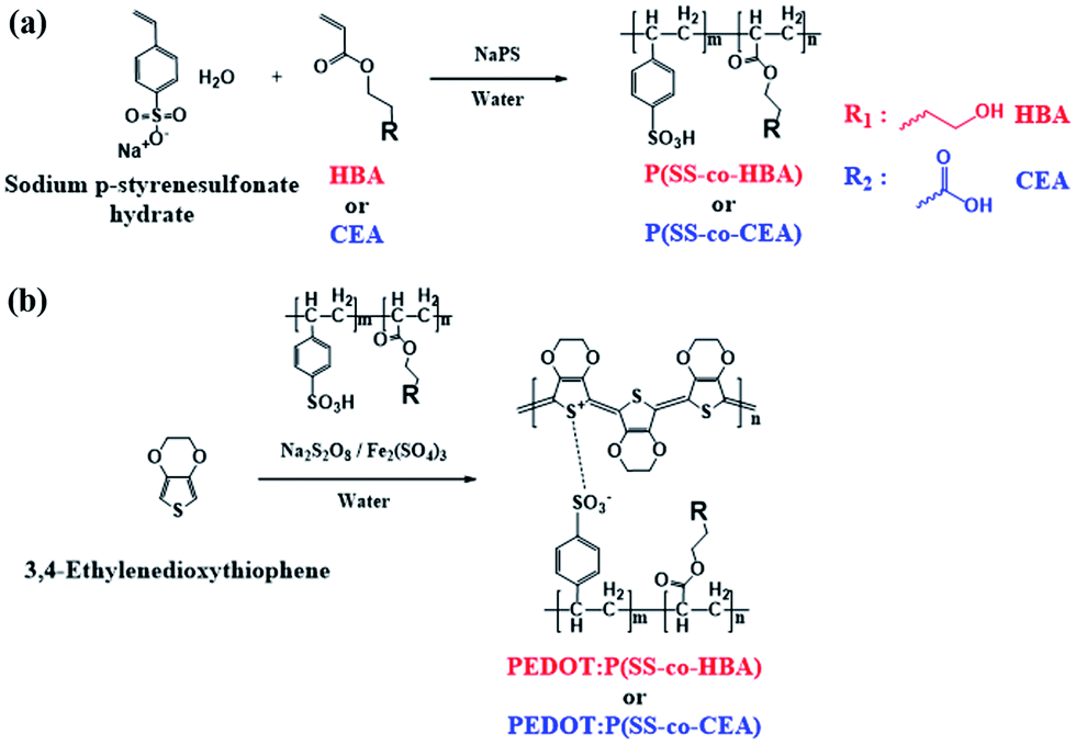 | ||
| Scheme 1 Synthesis of P(SS-co-HBA), P(SS-co-CEA) (a), and PEDOT:P(SS-co-HBA), PEDOT:P(SS-co-CEA) (b). | ||
The resistance change ratio of the two newly developed PEDOT composite thin films on a PET substrate was lower than that of a PEDOT:PSS thin film on PET because of the crosslinking effect. Also, the PEDOT composites were applied as electrodes to PVDF-based PNGs with an electrode/PVDF/electrode structure. PNG-2D(60) and PNG-3D(60) comprising PEDOT:P(SS-co-HBA) and PEDOT:P(SS-co-CEA), respectively, showed higher output and charging performance owing to their relatively higher electrical conductivities and the formation of an efficient homogeneous conductive network by the crosslinking effect even at a mild temperature (60 °C).
Experimental
Materials
Sodium p-styrenesulfonate hydrate, 4-hydroxybutyl acrylate (HBA), 2-carboxyethyl acrylate (CEA), sodium persulfate, and iron(III) sulfate hydrate were purchased from Sigma Aldrich. 3,4-Ethylenedioxythiophene (EDOT; TCI) and DI water (Fisher Scientific Korea Ltd.) were used without further purification. The PVDF film with a thickness of 80 μm was purchased from Fils Co. Ltd.Synthesis of anionic polyelectrolytes
![[thin space (1/6-em)]](https://www.rsc.org/images/entities/char_2009.gif) 648 Da; PDI: 4.469).
967 Da; PDI: 4.090).
691 Da, PDI: 4.022).
648 Da; PDI: 4.469).
967 Da; PDI: 4.090).
691 Da, PDI: 4.022).
Synthesis of PEDOT:P(SS-co-HBA) and PEDOT:P(SS-co-CEA)
The synthetic processes of the two anionic polyelectrolytes and the two PEDOT composites are shown in Scheme 1. PEDOT:PSS was synthesized using the same method to confirm the crosslinking effect of the synthesized PEDOT composites.
Fabrication of PVDF-based PNGs with PEDOT composites
PEDOT:P(SS-co-HBA) and PEDOT:P(SS-co-CEA) solutions and 0.5% FS-31 were added to PEDOT:PSS to enhance the coating of the PVDF film, and the mixture was filtered using a 5.0 μm nylon filter before use.The above solutions were spin-coated on a PVDF film (60 × 60 mm2) at 1000 rpm for 30 s, followed by drying at RT or annealing at 60 °C. The same method was used to form a thin film on the other side to prepare PNGs with a PEDOT composite/PVDF/PEDOT composite structure. Finally, they were cut to a size of 20 × 40 mm2 before use.
Characterization
Proton nuclear magnetic resonance (1H-NMR) spectroscopy (Bruker ARX 400 spectrometer) was performed to analyze the structures of PSS, P(SS-co-HBA), and P(SS-co-CEA) based on their chemical shifts recorded in ppm. The molecular weights of PSS, P(SS-co-HBA), and P(SS-co-CEA) were analyzed by gel permeation chromatography (EcoSEC HLC-8320 GPC) using PSS samples of various molecular weights as standard substances. The measurements were performed at a rate of 1.0 ml min−1 using pH 9 buffer-added 30% methanol. ATR-FTIR spectroscopy was conducted to identify the structure of PVDF using a Fourier-transform infrared spectroscope (FT/IR 4100, JASCO). A KRÜSS DSA 100 drop shape analyzer was used to measure the contact angle of DI water on the samples. Raman spectroscopy (InVia Raman microscope, Reinshaw) was performed through excitation with a 532 nm laser. An HP 4156A precision semiconductor parameter analyzer was used to measure the resistance, and the sheet resistance was calculated by multiplying the correction coefficient (4.532). Using this value and the thin film thickness, the specific resistance was obtained, and the conductivity was calculated from the reciprocal of specific resistance. The morphologies of the samples were observed on an area of 1 × 1 μm2 using a Park XE-100 atomic force microscope in the non-contact tapping mode.The performances of the produced PNGs were evaluated by fixing one end of the PNGs to a homemade tester and repeatedly measuring their stretch and release performed in the uniaxial direction. The measurement conditions were a 2.0 Hz frequency with 0.32 mm displacement. The output voltages and currents were measured using a Keithley DMM7510 graphical sampling multimeter. The crystalline structures of PEDOT:PSS, PEDOT:P(SS-co-HBA), and PEDOT:P(SS-co-CEA) thin films at RT and 60 °C were characterized with two-dimensional grazing incidence wide angle X-ray scattering (2D-GIWAXS) at the 3C beamline of the Pohang Accelerator Laboratory (PAL).
Results and discussion
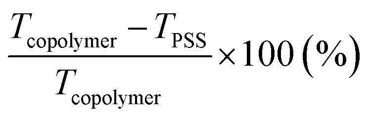
Scheme 1 shows the synthetic processes of the two types of anionic polyelectrolytes P(SS-co-HBA) and P(SS-co-CEA) (Scheme 1(a)) and those of the two PEDOT composites (Scheme 1(b)) doped with the anionic polyelectrolytes. The two synthesized anionic polyelectrolytes were used as dopants in the oxidative polymerization of EDOT for the synthesis of PEDOT:P(SS-co-HBA) and PEDOT:P(SS-co-CEA) (Scheme 1(b)). SS and HBA or CEA were introduced at a 9:1 molar ratio so that the anionic PSS counterpart in the two polyelectrolytes could sufficiently dope the PEDOT main chain. The condensation reaction between the –OH groups of HBA and CEA and the –SO3H group of SS generated a crosslink by eliminating water molecules, and the crosslinking density increased with increasing annealing temperature.
Fig. S1(a–c)† show the chemical structures of the three co-polymers: PSS, P(SS-co-HBA), and P(SS-co-CEA), and the 1H-NMR spectra are shown in Fig. S1(d).† The proton peaks (A & B) corresponding to the aromatic ring of PSS in the three polymers appeared at around 7.4 and 6.5 ppm, respectively. For the protons present in the PSS main backbone, the peak (C) appeared at around 1.5 ppm. The integration area of peak A:B:C was 2:1.98:2.78, which is almost the same as the theoretical ratio 2:2:3. The proton peaks corresponding to the aromatic ring present in P(SS-co-HBA) appeared at around 7.4 and 6.5 ppm, while the proton peaks (D) arising from the main chain (–CHCH2–) appeared at around 1.5 ppm, showing a similar pattern to that of PSS. The proton peaks (D′ & E) originating from the butyl group (–O(CH2)4O–) present in HBA within P(SS-co-HBA) appeared at around 1.5 ppm and 3.5–3.2 ppm, respectively.29 The proton peaks (A, B, and D) of P(SS-co-CEA) appeared at similar positions (ppm) to those mentioned above, while the proton peaks (F) of (–OCH2CH2O–) present in CEA appeared at around 3.7 and 2.4 ppm.30 The molar ratio of the acrylate units (HBA or CEA) present in each copolymer was calculated from the total integration area (T: sum from A to F) of the copolymers using eqn (1).
 | (1) |
The molar ratios were 10.1% for P(SS-co-HBA) and 9.6% for P(SS-co-CEA), which are close to the actual molar content of 10 mol%.
Fig. S2(a–c)† show the FTIR spectra of PSS, P(SS-co-HBA), and P(SS-co-CEA) according to the annealing conditions (RT, 60 °C, and 140 °C). As P(SS-co-HBA) and P(SS-co-CEA) contain PSS, the skeletal vibration peaks corresponding to the C![[double bond, length as m-dash]](https://www.rsc.org/images/entities/char_e001.gif) C bond present in the phenyl ring appeared at 1680 cm−1 and 1495–1411 cm−1, similar to the FTIR spectrum of PSS. The broad peaks in the range of 1240–1120 cm−1 were attributed to the asymmetric stretching vibration of the SO3− group, while those in the range of 1030–1000 cm−1 were attributed to the symmetric stretching vibration of the SO3− group.26 P(SS-co-HBA) and P(SS-co-CEA) displayed vibration peaks at 1720–1710 cm−1 due to the stretching of the CO bond present in the HBA and CEA units. In the case of PSS, the vibration peaks did not change with temperature (RT, 60 °C, and 140 °C). However, for P(SS-co-HBA) and P(SS-co-CEA), the vibration peaks of the C–O bond at 1160–1150 cm−1 increased when the temperature was increased to 60 °C and 140 °C. As shown in Fig. 1(a), the –OH groups in the HBA and CEA acrylic units form a sulfonate ester group in the condensation reaction with the –SO3H group of the PSS unit and become crosslinked.25,31 The crosslinking effect does not occur at RT, partially takes place at a mild temperature of 60 °C, and is relatively higher at a high temperature of 140 °C.
C bond present in the phenyl ring appeared at 1680 cm−1 and 1495–1411 cm−1, similar to the FTIR spectrum of PSS. The broad peaks in the range of 1240–1120 cm−1 were attributed to the asymmetric stretching vibration of the SO3− group, while those in the range of 1030–1000 cm−1 were attributed to the symmetric stretching vibration of the SO3− group.26 P(SS-co-HBA) and P(SS-co-CEA) displayed vibration peaks at 1720–1710 cm−1 due to the stretching of the CO bond present in the HBA and CEA units. In the case of PSS, the vibration peaks did not change with temperature (RT, 60 °C, and 140 °C). However, for P(SS-co-HBA) and P(SS-co-CEA), the vibration peaks of the C–O bond at 1160–1150 cm−1 increased when the temperature was increased to 60 °C and 140 °C. As shown in Fig. 1(a), the –OH groups in the HBA and CEA acrylic units form a sulfonate ester group in the condensation reaction with the –SO3H group of the PSS unit and become crosslinked.25,31 The crosslinking effect does not occur at RT, partially takes place at a mild temperature of 60 °C, and is relatively higher at a high temperature of 140 °C.
 | ||
| Fig. 1 Crosslinking by removing water molecules in P(SS-co-HBA) and P(SS-co-CEA) (a) and schematic illustration of the crosslinking effect in PEDOT:P(SS-co-HBA) and PEDOT:P(SS-co-CEA) according to annealing temperature: RT (b), 60 °C (c), and 140 °C (d). | ||
Fig. S3(a–c)† show the contact angle images obtained using water droplets on the thin films of the three anionic polyelectrolytes formed at RT, 60 °C, and 140 °C. The contact angles of the PSS films prepared at RT, 60 °C, and 140 °C are 12.7°, 13.0°, and 12.9°, respectively, showing no change in the contact angle with temperature. On the other hand, P(SS-co-HBA) (Fig. S3(d–f)†) displayed contact angles of 12.7°, 14.0°, and 22.0°, showing an increase in the contact angle with increasing temperature. However, P(SS-co-CEA) (Fig. S3(g–i)†) displayed a slight increase in the contact angle (12.8°, 15.0°, and 16.3°) with increasing temperature (RT, 60 °C, and 140 °C, respectively). As confirmed by FTIR analysis, PSS maintained its relatively hydrophilic property irrespective of temperature, whereas P(SS-co-HBA) and P(SS-co-CEA) became increasingly hydrophobic due to the crosslinking effect caused by an increase in temperature.
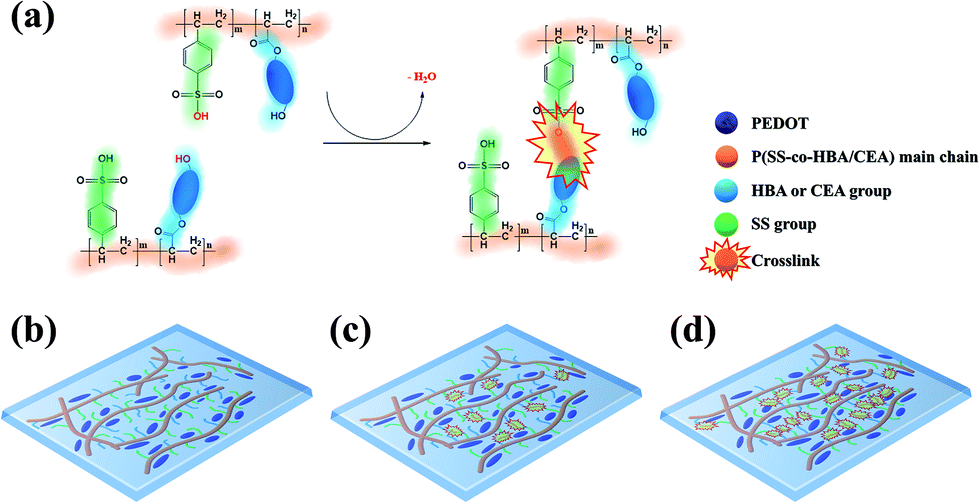
Fig. 2 shows the contact angle images obtained using water droplets on the thin films of the three PEDOT:PSS composites incorporating the PSS derivatives. PEDOT:PSS displayed contact angles of 19.1°, 19.6°, and 19.5° (Fig. 2(a–c)), showing no change in the contact angle with an increase in temperature (RT, 60 °C, and 140 °C, respectively), similar to that seen in Fig. S3(a–c).† PEDOT:P(SS-co-HBA) (Fig. 2(d–f)) displayed an increase in contact angle (20.2°, 22.4°, and 38.5°) with increasing annealing temperature (RT, 60 °C, and 140 °C, respectively), similar to that seen in Fig. S3(d–f).† This indicates that as P(SS-co-HBA) became crosslinked, it acquired a relatively hydrophobic property. Similarly, PEDOT:P(SS-co-CEA) (Fig. 2(g–i)) displayed contact angles of 22.4°, 24.5°, and 31.7°, which indicated that the composites are relatively hydrophobic due to the crosslinking effect, as seen in Fig. S3(g–i).† CEA has a short hydrocarbon unit comprising two carbonyl groups and an ethyl group within its structure. On the other hand, HBA has a longer hydrocarbon unit comprising one carbonyl group and a butyl group; thus, the level of increase in the hydrophobic property due to the crosslinking effect was higher.32
 | ||
| Fig. 2 Contact angle images of DI water droplets on the PEDOT:PSS film ((a) RT), ((b) 60 °C), ((c) 140 °C), PEDOT:P(SS-co-HBA) film ((d) RT), ((e) 60 °C), ((f) 140 °C), and PEDOT:P(SS-co-CEA) film ((g) RT), ((h) 60 °C), ((i) 140 °C) at various annealing temperatures. | ||
To calculate the sheet resistances and electrical conductivities of PEDOT:PSS, PEDOT:P(SS-co-HBA), and PEDOT:P(SS-co-CEA) films according to temperature, the resistance of each PEDOT composite film was measured using a precision semiconductor parameter analyzer. The thickness of all the films was 40 nm. In the case of PEDOT:PSS without the crosslinking effect, the sheet resistances were −8.86% and −18.06% for annealing temperatures of 60 °C and 140 °C, which showed a low reduction rate compared with the sheet resistance of the film dried at RT. In contrast, the sheet resistances of PEDOT:P(SS-co-HBA), which showed an increasing crosslinking effect with temperature, changed by −44.80% (60 °C) and −53.88% (140 °C) compared with that of the film dried at RT, while the sheet resistances of PEDOT:P(SS-co-CEA) changed by −35.71% (60 °C) and −45.97% (140 °C). Thus, the electrical conductivities calculated using the sheet resistance and thickness were 0.21 (RT), 0.23 (60 °C), and 0.25 S cm−1 (140 °C) for PEDOT:PSS, showing no marked changes; 0.47 (RT), 0.86 (60 °C), and 1.02 S cm−1 (140 °C) for PEDOT:P(SS-co-HBA); and 0.23 (RT), 0.36 (60 °C), and 0.42 S cm−1 (140 °C) for PEDOT:P(SS-co-CEA). This indicated an improvement in electrical properties owing to the crosslinking effect caused by an increase in temperature. To enhance the electrical conductivities, 5% dimethyl sulfoxide (DMSO), an additive, was added to all PEDOT composite solutions, respectively.33,34 The samples showed enhanced properties due to the additive effect. However, the electrical conductivities were 14.84 (RT), 41.49 (60 °C), and 46.49 S cm−1 (140 °C) for DMSO-treated PEDOT:P(SS-co-HBA) and 7.62 (RT), 23.18 (60 °C), and 39.08 S cm−1 (140 °C) for DMSO-treated PEDOT:P(SS-co-CEA), which are much higher than those of DMSO-treated PEDOT:PSS. The enhancement of electrical properties by the crosslinking effect was also valid after adding DMSO. The results are summarized in Table 1.
| Annealing temperature (°C) | Pristine | With 5% DMSO | Contact angle (°) | ||||
|---|---|---|---|---|---|---|---|
| Sheet resistance (×104 ohm sq−1) | Conductivity (S cm−1) | Sheet resistance (×104 ohm sq−1) | Conductivity (S cm−1) | PEDOT composite | Anionic polyelectrolyte | ||
| PEDOT:PSS | RT | 120.7 | 0.21 | 4.81 | 5.20 | 19.1 | 12.7 |
| 60 °C | 110.0 | 0.23 | 1.99 | 12.57 | 19.6 | 13.0 | |
| 140 °C | 98.9 | 0.25 | 1.19 | 20.94 | 19.5 | 12.9 | |
| PEDOT:P(SS-co-HBA) | RT | 52.9 | 0.47 | 1.68 | 14.84 | 20.2 | 12.7 |
| 60 °C | 29.2 | 0.86 | 0.60 | 41.49 | 22.4 | 14.0 | |
| 140 °C | 24.4 | 1.02 | 0.54 | 46.49 | 38.5 | 22.0 | |
| PEDOT:P(SS-co-CEA) | RT | 109.2 | 0.23 | 3.28 | 7.62 | 22.4 | 12.8 |
| 60 °C | 70.2 | 0.36 | 1.08 | 23.18 | 24.5 | 15.0 | |
| 140 °C | 59.0 | 0.42 | 0.64 | 39.08 | 31.7 | 16.3 | |
To examine the structural changes caused by the crosslinking effect, the Raman spectra of the three PEDOT composites are shown in Fig. 3. A strong CαCβ symmetric stretching vibration band corresponding to the five-membered thiophene present in PEDOT appeared at 1400–1500 cm−1. PEDOT:PSS did not exhibit a band shift due to temperature. The PEDOT:P(SS-co-HBA) film dried at RT displayed the CαCβ band at 1437.04 cm−1. For the 60 °C and 140 °C annealed films, the band red-shifted to 1435.98 cm−1. This indicates a change in the resonant structure of the PEDOT chains from a benzoid structure with a preferred random coil conformation to a quinoid structure with a preferred expanded coil conformation or linear conformation. The PEDOT:P(SS-co-CEA) film dried at RT displayed the CαCβ band at 1438.21 cm−1, which red-shifted to 1437.23 cm−1 and 1437.07 cm−1 for the films annealed at 60 °C and 140 °C, respectively. The results suggest that the crosslinking effect led to a change in the PEDOT structure even at a mild temperature (60 °C), which is consistent with the increase in conductivity with temperature.35,36
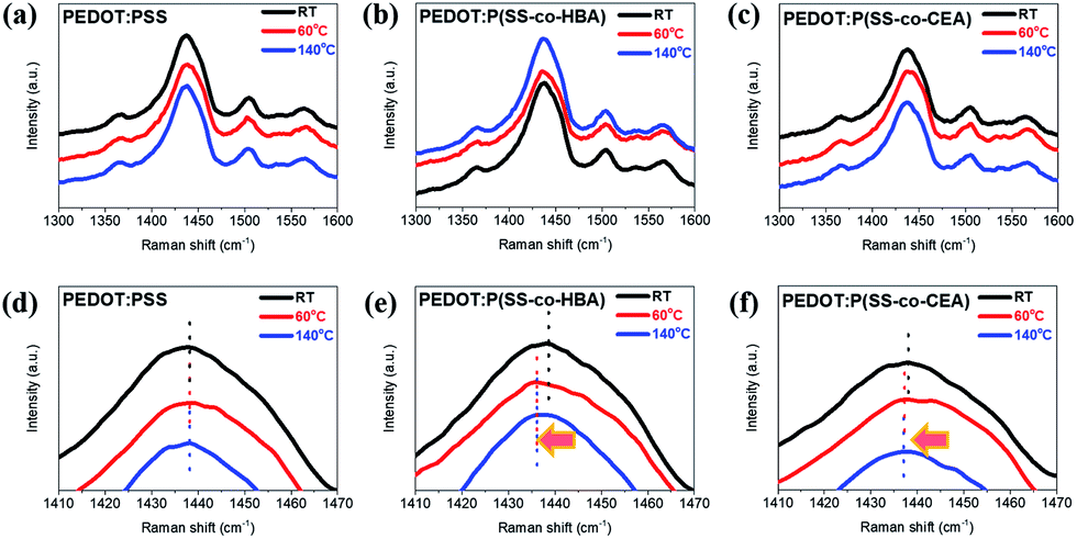 | ||
| Fig. 3 Raman spectra of PEDOT:PSS (a), PEDOT:P(SS-co-HBA) (b), and PEDOT:P(SS-co-CEA) (c) films at various annealing temperatures. Enlarged Raman spectra (d–f) in the range of 1410–1470 cm−1 of (a–c), respectively. | ||
Surface roughness and uniformity are two of the crucial determinants of electrical properties. Fig. S4† shows the AFM images of PEDOT:PSS (Fig. S4(a–c)†), PEDOT:P(SS-co-HBA) (Fig. S4(d–f)†), and PEDOT:P(SS-co-CEA) (Fig. S4(g–i) †) films to examine the changes in the morphology caused by the crosslinking effect (RT, 60 °C, and 140 °C). As shown by the topographic images (left images in Fig. S4(a–i)†), the root mean square (RMS) roughnesses were 1.320 (RT), 1.474 (60 °C), and 1.428 nm (140 °C) for PEDOT:PSS; 1.226 (RT), 1.147 (60 °C), and 1.320 nm (140 °C) for PEDOT:P(SS-co-HBA); and 1.146 (RT), 1.246 (60 °C), and 1.223 nm (140 °C) for PEDOT:P(SS-co-CEA). The values suggest an overall smooth morphology.
The bright and dark regions on the phase images (right images in Fig. S4(a–i)†) indicate PEDOT-rich and insulating PSS-, P(SS-co-HBA)-, and P(SS-co-CEA)-rich grains.37 For PEDOT:PSS, the phase images (Fig. S4(a–c)†) show phase separation with nanoaggregates of similar sizes, created without marked changes due to the annealing temperature. For PEDOT:P(SS-co-HBA) (Fig. S4(d–f)†), a large PEDOT grain is seen at RT (Fig. S4(d)†), with an excellent conductive network leading to a higher conductivity than that of the PEDOT:PSS film. The films formed at 60 °C (Fig. S4(e)†) and 140 °C (Fig. S4(f)†) show that the crosslinking effect in P(SS-co-HBA) led to the formation of a continuously connected nanofibril-like network by the smaller PEDOT grains; this is in agreement with its excellent electrical conductivity. For PEDOT:P(SS-co-CEA) (Fig. S4(g–i)†), similar phase separation behavior to that seen for PEDOT:PSS was observed at RT (Fig. S4(g)†).
At 60 °C (Fig. S4(h)†), however, partially isolated insulating P(SS-co-CEA) aggregation can be seen, while an overall homogeneously dispersed network was formed by the PEDOT particles. On the other hand, at 140 °C (Fig. S4(i)†), the crosslinking effect of P(SS-co-CEA) produced a large phase separation that increased the distances between the PEDOT networks, preventing the formation of a conductive network. This suggested that the improvement in electrical conductivity based on the crosslinking effect was not substantial.
According to the Wenzel model, the contact angle (<90°) decreases as the surface roughness increases.38 The result indicated no significant changes in the RMS roughness due to the annealing temperature in the cases of PEDOT:P(SS-co-HBA) and PEDOT:P(SS-co-CEA) comprising the hydrophilic PEDOT:PSS.
Such a finding lends further support to our claim that the increases in relative hydrophobicity of the PEDOT:P(SS-co-HBA) and PEDOT:P(SS-co-CEA) films are caused by the crosslinking effect and are not due to the effect of roughness.
To examine the resistance change in the PEDOT composite films formed by the crosslinking effect using a bending test, the samples spin-coated on PET films were measured for 1000 cycles under the conditions of 2 mm displacement and 5 mm s−1 speed, and the results are shown in Fig. S5.† The R/R0 ratios of PEDOT:PSS after 1000 cycles were 2.49 (RT), 2.19 (60 °C), and 2.53 (140 °C), while those of PEDOT:P(SS-co-HBA) were 1.49 (RT), 1.17 (60 °C), and 1.15 (140 °C). This revealed that the crosslinking effect made the composite relatively hydrophobic, thus reducing the surface energy gap with PET, a hydrophobic material, which in turn reduced the resistance change, consequently improving the stability.28
PEDOT:P(SS-co-CEA) showed R/R0 ratios of 1.29 (RT), 1.17 (60 °C), and 1.38 (140 °C), exhibiting a slight increase in the values. This may be attributed to the carboxyl groups in CEA that are more hydrophilic than the butyl groups in HBA. Hence, the remaining carboxyl groups that may be present after the crosslinking made it relatively hydrophilic, leading to a higher resistance change. Nonetheless, the result is excellent compared with the result of the more hydrophilic PEDOT:PSS.
PEDOT:PSS, PEDOT:P(SS-co-HBA), and PEDOT:P(SS-co-CEA) were each applied as an electrode in PVDF-based PNGs to prepare sandwich-type PNGs named PNG-1, PNG-2, and PNG-3, respectively, as shown in Fig. S6(a).† The piezoelectric coefficient of β-PVDF decreases upon exposure to a temperature of approximately 80 °C or above, and the synthesized PEDOT composites exhibited excellent properties even at a mild temperature of 60 °C. Thus, all the PEDOT composite films were formed at RT and 60 °C after spin-coating on PVDF. Even at a mild temperature, the crosslinking effect was slightly produced, which improved the electrical properties, thereby improving the piezoelectric output performance. The samples dried at RT (Fig. S6(a–c)†) and those annealed at 60 °C (Fig. S6(d–f)†) were marked as RT or 60 at the end of their name. One side of the PNGs (RT and 60) was fixed to a tester, and the other side was stretched and released repeatedly in the uniaxial direction. The top and bottom PEDOT composite films were connected to a multimeter and measurements were taken under the conditions of 2.0 Hz frequency and 0.64 mm s−1 drive speed while repeatedly stretching and releasing the film for 0.32 mm displacement (0.8% strain). When there is no strain (Fig. S6(a)†), the output is zero with no dipole moment change. However, stretching in the uniaxial direction (Fig. S6(b)†) decreases the total polarization of β-PVDF, resulting in a change in the piezoelectric potential. As a result, holes in the top electrode and electrons in the bottom electrode drift and accumulate in the opposite directions along the outer circuit, resulting in a positive output signal. After releasing the film (Fig. S6(c)†), the immediately generated potentials disappear and the drifted and accumulated charges return to their original state, generating a negative output signal.28
The result is presented as output voltage (Fig. 4(a)), output current (Fig. 4(b)), and output power (Fig. 4(c and d)) according to various load resistances. The average output voltage (Vavg, V) and the average output current (Iavg, nA) of the prepared PNGs were 2.31 V and 444.6 nA for PNG-1(RT); 3.28 V and 636.7 nA for PNG-2(RT); and 2.62 V and 633.6 nA for PNG-3(RT), respectively. In the case of PNGs(60), the Vavg and Iavg values were 2.47 V and 460.5 nA for PNG-1(60); 3.76 V and 693.1 nA for PNG-2(60); and 2.88 V and 695.2 nA for PNG-3(60), respectively, with PNG-2(60) and PNG-3(60) showing improved output performances than PNG-1(60) due to the crosslinking effect. Notably, the voltage and current of PNG-2(60) comprising PEDOT:P(SS-co-HBA) improved by approximately 14.6% and 8.9%, respectively. As shown in Fig. 4(c and d) and Fig. S7,† by connecting them to a decade box, the output voltages at various load resistances (1–11, 111, 110 MΩ) were measured, and the maximum output power (nW) was calculated using eqn (2).
 | (2) |
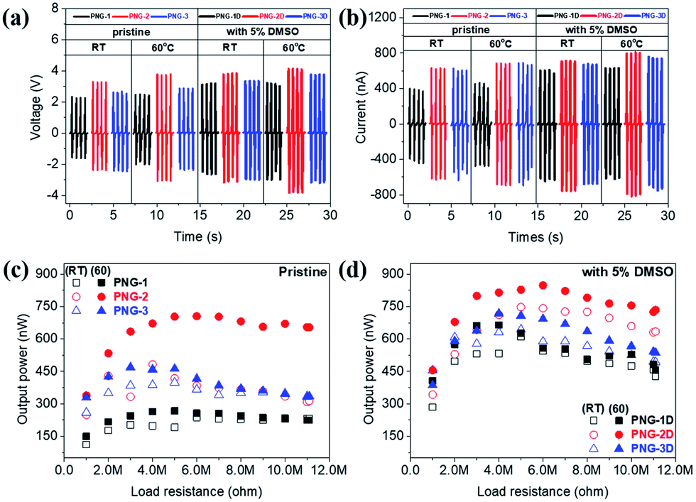 | ||
| Fig. 4 Piezoelectric output performance of PNG-1/1D (black), PNG-2/2D (red), and PNG-3/3D (blue); output voltages ((a) RT and 60) and output currents ((b) RT and 60) indicated with thin lines (pristine) and thick lines (with 5% DMSO), and the output power of PNG-(1–3) ((c) pristine) and PNG-(1–3)D ((d) with 5% DMSO) indicated with hollow shapes (RT) and solid shapes (60) at various load resistances. | ||
The maximum output powers of PNG-1(RT), PNG-2(RT), and PNG-3(RT) were 237.2, 482.4, and 399.1 nW at 6, 4, and 5 MΩ, respectively, while those of PNG-1(60), PNG-2(60), and PNG-3(60) were 267.7, 705.2, and 468.7 nW at 5, 6, and 3 MΩ, respectively. All the PNGs exhibited increased outputs after annealing, with a higher level of increase at 60 °C than at RT. The difference was insignificant for PNG-1 where PEDOT:PSS was applied without the crosslinking effect. On the contrary, PNG-2 and PNG-3, where PEDOT:P(SS-co-HBA) and PEDOT:P(SS-co-CEA) were, respectively, applied with the crosslinking effect, showed 46.2% and 17.4% improvements in the maximum output power, respectively, compared with that at RT, and 263.4% and 175.1% improvements, respectively, compared with those of PNG-1(60), indicating an enhanced performance.
To get higher output power, DMSO-treated PEDOT composites were introduced as electrodes for PNGs, which are named PNG-1D, PNG-2D, and PNG-3D. The Vavg and Iavg values were 3.17 V and 646.5 nA for PNG-1D(RT); 3.83 V and 758.7 nA for PNG-2D(RT); and 3.35 V and 677.6 nA for PNG-3D(RT), respectively. In the case of PNGs-D(60), 3.19 V and 630.0 nA for PNG-1D(60); 4.12 V and 817.3 nA for PNG-2D(60); 3.75 V and 756.5 nA for PNG-3D(60), respectively. The maximized output power of PNGs-D(60) is 665.0 nW at 4 MΩ, 847.5 nW at 6 MΩ, and 716.9 nW at 4 MΩ, respectively. The detailed output performances of all PNGs at various load resistances are demonstrated in Fig. S7 and S8.†
The most outstanding performance was obtained for PNG-2D comprising PEDOT:P(SS-co-HBA) which showed the highest electrical conductivity (∼3.3 times higher than that of PEDOT:PSS) based on the crosslinking effect. This was followed by PNG-3D comprising PEDOT:P(SS-co-CEA) which showed the second highest electrical conductivity (∼1.8 times higher than that of PEDOT:PSS). The crosslinking effect converted the structure of PEDOT into a quinoid structure, thereby improving the electrical properties of PEDOT as an electrode, and the output increased in proportion to the improved electrical properties.28,39 The results are summarized in Table 2.
| Voltage (V) | Current (nA) | Resistance (MΩ) | Power (nW) | |
|---|---|---|---|---|
| PNG-1(RT) | 2.31 | 444.6 | 6 | 237.2 |
| PNG-2(RT) | 3.28 | 636.7 | 4 | 482.4 |
| PNG-3(RT) | 2.62 | 633.6 | 5 | 399.1 |
| PNG-1(60) | 2.47 | 460.5 | 5 | 267.7 |
| PNG-2(60) | 3.76 | 693.1 | 6 | 705.2 |
| PNG-3(60) | 2.88 | 695.2 | 3 | 468.7 |
| PNG-1D(RT) | 3.17 | 646.5 | 5 | 611.1 |
| PNG-2D(RT) | 3.83 | 758.7 | 5 | 747.3 |
| PNG-3D(RT) | 3.35 | 677.6 | 5 | 643.9 |
| PNG-1D(60) | 3.19 | 630.0 | 4 | 665.0 |
| PNG-2D(60) | 4.12 | 817.3 | 6 | 847.5 |
| PNG-3D(60) | 3.75 | 756.5 | 4 | 716.9 |
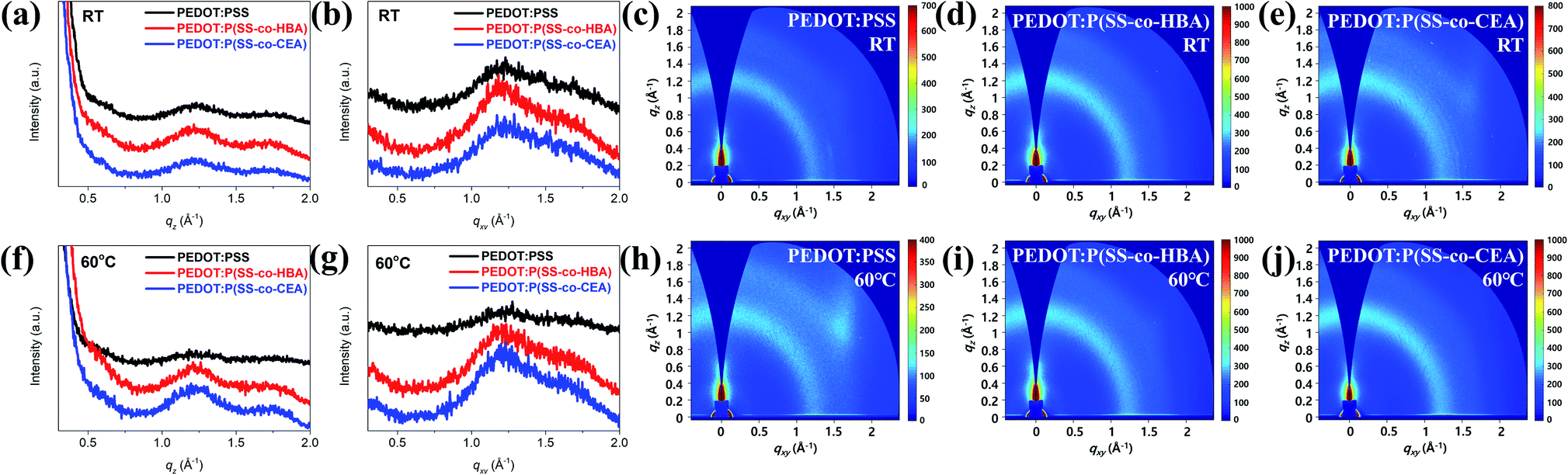
Fig. 5 shows the GIWAXS line-cut profiles (Fig. 5(a, b and f, g)) and images (Fig. 5(c–e and h–j)) of the PEDOT:PSS, PEDOT:P(SS-co-HBA), and PEDOT:P(SS-co-CEA) thin films. As can be seen, the profiles are mostly amorphous without a distinct peak.
 | ||
| Fig. 5 GIWAXS line-cut profiles and images of PEDOT:PSS, PEDOT:P(SS-co-HBA), and PEDOT:P(SS-co-CEA) films: RT (a–e) and 60 °C (f–j). | ||
As shown in Fig. 5(a and f), the three PEDOT composite films display a weak and broad PEDOT (200) lamellar peak at qz = 0.58 Å−1 (d = 10.83 Å). In addition, a broad π–π stacking peak was displayed by amorphous PSS and PEDOT (010) at qz = 1.21 Å−1 (d = 5.19 Å) and qz = 1.77 Å−1 (d = 3.55 Å), respectively. As shown in Fig. 5(b and g), no (h00) lamellar peak was detected for all the films, and a broad peak emerged at qxy = 1.7–1.8 Å−1, indicating that the PEDOT chains formed an edge-on orientation. However, as can be seen in Fig. 5(c–e and h–j), the q values represent a ring pattern, whereby randomly oriented π–π stacking forms.40,41 Applying a small amount (10 mol%) of HBA and CEA to the PSS chain did not to exert a significant influence on the orientation of the PEDOT chain based on the crosslinking effect, and as in a general PEDOT:PSS, an edge-on oriented structure was formed. Such a structural orientation contributes to output enhancements of the PNGs.28
As shown in Fig. S9,† the Vavg of PNG-(1D–3D)(60) for the stability test was measured after 20 days of storage in exposed air. The Vavg after 20 days was 2.20 V for PNG-1D(60), decreased about 1 V (∼31%); 3.93 V for PNG-2D(60), decreased about 0.19 V (∼4.6%); and 3.33 V for PNG-3D(60), decreased about 0.42 V (∼11.2%). The reduction rate of PNG-2D and PNG-3D is less than that of PNG-1D. The PEDOT:PSS film easily absorbs water molecules from air and becomes weaker due to the hygroscopic nature of PSS. The crosslinking system of P(SS-co-HBA) and P(SS-co-CEA) is efficient in preventing water penetration. Also, the PSS molar ratios of the two anionic polyelectrolytes are less than that of original PSS, and they represent relatively low acidity, PEDOT:PSS of pH 1.8, PEDOT:P(SS-co-HBA) of pH 2.0, and PEDOT:P(SS-co-CEA) of pH 2.0 measured using a pH meter.42–45
The PEDOT composite is one of the critical conductive materials for flexible electronics applications such as nanogenerators, sensors, photodetectors, memristors etc. due to its flexibility, transparency and electrical properties.46–51 Especially, flexible PVDF-based PNGs with PEDOT composites can be some of the ways to supply energy to self-powered systems. The PNG-(1D–3D)(60) samples were tested for use in sensing applications by finger and wrist bending and releasing motions as shown in Fig. 6. The output voltage signals, regardless of the body parts, have good repeatability at both low and high bending angles (15–60°) representing positive signals in the bent state and negative signals in the released state. In the case of PNG-2D(60) and PNG-3D(60), they showed relatively sensitive signals compared to PNG-1D(60). The results indicate their possible application for motion detection in healthcare systems.
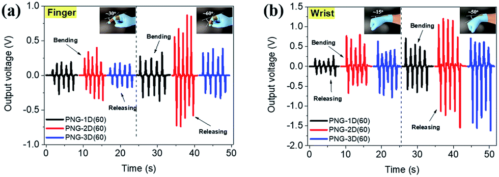 | ||
| Fig. 6 The output voltages of PNG-(1D–3D)(60) for a body motion monitoring system; tested using a finger at two bending angles (∼30° and ∼60°) (a) and a wrist at two bending angles (∼15° and ∼50°) (b). | ||
Also, Fig. S10† shows the charging performances of the PNGs-(1–3) evaluated by connecting them to a bridge circuit and a 1 μF capacitor, as shown in Fig. S10(d).† The conditions were identical to those shown in Fig. S6,† and the frequency was measured in the range of 1 to 5 Hz. At 1 Hz, PNG-(1–3)(RT) charged a 1 μF capacitor to 0.80, 0.86, and 0.86 V in 60 s, respectively, while PNG-(1–3)(60), which showed enhanced outputs, charged the capacitor to 0.80, 0.97, and 0.90 V, respectively. For PNG-1, the charging performances were not significantly different at RT and 60 °C; however, for PNG-2 and PNG-3, the outputs improved by 12.8% and 4.7%, respectively. Similar improvement trends were observed with a change in frequency. At 5 Hz, PNG-(2 and 3)(60) charged the capacitor to 4.63 V and 3.73 V, respectively, exhibiting adequate performances as power sources using mechanical energy. These values are summarized in Table S1.†
Conclusions
In this study, two types of PEDOT composites (PEDOT:P(SS-co-HBA) and PEDOT:P(SS-co-CEA)) that exhibited outstanding electrical properties and stability based on the crosslinking effect were synthesized. For adequate doping of PEDOT by PSS, small quantities of HBA and CEA were added, respectively, in 9:1 molar ratio to PSS. Nevertheless, the crosslinking effect was observed to increase with increasing annealing temperature from RT to 60 °C and 140 °C, leading to a reduction in sheet resistance by −36% to −54% with an increase in electrical conductivity. The PEDOT grains formed a homogeneously dispersed network due to the slight crosslinking effect even at a mild temperature, resulting in improved electrical properties.
PNG-2(60) and PNG-3(60) comprising PEDOT:P(SS-co-HBA) and PEDOT:P(SS-co-CEA), respectively, were applied as electrodes, and exhibited 13.4% and 11.3% improvements in the maximum output power, respectively, which were to a greater degree at a mild temperature (60 °C) than at RT. Compared with PNG-1D(60) in which PEDOT:PSS was applied with no crosslinking effect, the maximum output power improved by 27.4% and 7.8%. PNGs showed good sensitivity as body motion sensors and the charging performance also showed proportional improvements, suggesting an adequate level of performance as a power source.
Conflicts of interest
There are no conflicts to declare.Acknowledgements
This research was supported by the New & Renewable Energy Core Technology Program of the Korea Institute of Energy Technology Evaluation and Planning (KETEP) grant funded by the Ministry of Trade, Industry and Energy, Republic of Korea (no. 20153010140030), and the Human Resources Program in Energy Technology of the Korea Institute of Energy Technology Evaluation and Planning (KETEP) granted financial resource from the Ministry of Trade, Industry and Energy, Republic of Korea (Grant No. 20194010201790).Notes and references
- F. R. Fan, W. Tang and Z. L. Wang, Adv. Mater., 2016, 28, 4283–4305 CrossRef CAS PubMed.
- Y. Zi and Z. L. Wang, APL Mater., 2017, 5, 074103 CrossRef.
- F. Narita and M. Fox, Adv. Eng. Mater., 2018, 20, 1–22 CrossRef.
- Y. Yang and W. Gao, Chem. Soc. Rev., 2018, 48, 1465–1491 RSC.
- J. S. Heo, J. Eom, Y. H. Kim and S. K. Park, Small, 2018, 14, 1–16 CrossRef PubMed.
- L. Peng, L. Hu and X. Fang, Adv. Funct. Mater., 2014, 24, 2591–2610 CrossRef CAS.
- W. Ouyang, F. Teng and X. Fang, Adv. Funct. Mater., 2018, 28, 1707178 CrossRef.
- Z. Zhang, Y. Ning and X. Fang, J. Mater. Chem. C, 2019, 7, 223–229 RSC.
- Z. Zhou, C. Lan, R. Wei and J. C. Ho, J. Mater. Chem. C, 2019, 7, 202–217 RSC.
- C. H. Lin, B. Cheng, T. Y. Li, J. R. D. Retamal, T. C. Wei, H. C. Fu, X. Fang and J. H. He, ACS Nano, 2019, 13, 1168–1176 CAS.
- W. Guo, C. Tan, K. Shi, J. Li, X. X. Wang, B. Sun, X. Huang, Y. Z. Long and P. Jiang, Nanoscale, 2018, 10, 17751–17760 RSC.
- N. P. Maria Joseph Raj, N. R. Alluri, V. Vivekananthan, A. Chandrasekhar, G. Khandelwal and S. J. Kim, Appl. Energy, 2018, 228, 1767–1776 CrossRef CAS.
- B. Liu, B. Lu, X. Chen, X. Wu, S. Shi, L. Xu, Y. Liu, F. Wang, X. Zhao and W. Shi, J. Mater. Chem. A, 2017, 5, 23634–23640 RSC.
- E. J. Lee, T. Y. Kim, S. W. Kim, S. Jeong, Y. Choi and S. Y. Lee, Energy Environ. Sci., 2018, 11, 1425–1430 RSC.
- E. J. Ko, E. J. Lee, M. H. Choi, T. H. Sung and D. K. Moon, Sens. Actuators, A, 2017, 259, 112–120 CrossRef CAS.
- K. Maity and D. Mandal, ACS Appl. Mater. Interfaces, 2018, 10, 18257–18269 CrossRef CAS PubMed.
- H. Yuan, T. Lei, Y. Qin, J. H. He and R. Yang, J. Phys. D: Appl. Phys., 2019, 51, 194002 CrossRef.
- B. Deng, P. C. Hsu, G. Chen, B. N. Chandrashekar, L. Liao, Z. Ayitimuda, J. Wu, Y. Guo, L. Lin, Y. Zhou, M. Aisijiang, Q. Xie, Y. Cui, Z. Liu and H. Peng, Nano Lett., 2015, 15, 4206–4213 CrossRef CAS PubMed.
- S. Kim, S. Y. Kim, J. Kim and J. H. Kim, J. Mater. Chem. C, 2014, 2, 5636–5643 RSC.
- H. Peng, W. Dang, J. Cao, Y. Chen, D. Wu, W. Zheng, H. Li, Z. X. Shen and Z. Liu, Nat. Chem., 2012, 4, 281–286 CrossRef CAS PubMed.
- K. Sun, S. Zhang, P. Li, Y. Xia, X. Zhang, D. Du, F. H. Isikgor and J. Ouyang, J. Mater. Sci.: Mater. Electron., 2015, 26, 4438–4462 CrossRef CAS.
- K. W. Song, T. H. Lee, E. J. Ko, K. H. Back and D. K. Moon, J. Polym. Sci., Part A: Polym. Chem., 2014, 52, 1028–1036 CrossRef CAS.
- H. J. Song, D. H. Kim, E. J. Lee, J. R. Haw and D. K. Moon, Sol. Energy Mater. Sol. Cells, 2014, 123, 112–121 CrossRef CAS.
- Z. Wang, J. Xu, Y. Yao, L. Zhang, Y. Wen, H. Song and D. Zhu, Sens. Actuators, B, 2014, 196, 357–369 CrossRef CAS.
- J. J. Lee, S. H. Lee, F. S. Kim, H. H. Choi and J. H. Kim, Org. Electron., 2015, 26, 191–199 CrossRef CAS.
- W. Cho, J. K. Hong, J. J. Lee, S. Kim, S. Kim, S. Im, D. Yoo and J. H. Kim, RSC Adv., 2016, 6, 63296–63303 RSC.
- D. Mantione, I. Del Agua, W. Schaafsma, M. Elmahmoudy, I. Uguz, A. Sanchez-Sanchez, H. Sardon, B. Castro, G. G. Malliaras and D. Mecerreyes, ACS Appl. Mater. Interfaces, 2017, 9, 18254–18262 CrossRef CAS PubMed.
- E. J. Ko, S. J. Jeon, Y. W. Han, S. Y. Jeong, C. Y. Kang, T. H. Sung, K. W. Seong and D. K. Moon, Nano Energy, 2019, 58, 11–22 CrossRef CAS.
- J. Lee, Y. Kim, C. Kim and M. Ree, Mater. Horiz., 2017, 4, 423–430 RSC.
- A. N. Mondal, C. Zheng, C. Cheng, M. M. Hossain, M. I. Khan, Z. Yao, L. Wu and T. Xu, RSC Adv., 2015, 5, 95256–95267 RSC.
- D. K. Lee, J. T. Park, D. K. Roh, B. R. Min and J. H. Kim, Macromol. Res., 2009, 17, 325–331 CrossRef CAS.
- X. Du, J. S. Li, L. X. Li and P. A. Levkin, J. Mater. Chem. A, 2013, 1, 1026–1029 RSC.
- H. Song, C. Liu, J. Xu, Q. Jiang and H. Shi, RSC Adv., 2013, 3, 22065–22071 RSC.
- X. Zhang, J. Wu, J. Wang, J. Zhang, Q. Yang, Y. Fu and Z. Xie, Sol. Energy Mater. Sol. Cells, 2016, 144, 143–149 CrossRef CAS.
- J. Ouyang, C. W. Chu, F. C. Chen, Q. Xu and Y. Yang, Adv. Funct. Mater., 2005, 15, 203–208 CrossRef CAS.
- T. R. Chou, S. H. Chen, Y. Te Chiang, Y. T. Lin and C. Y. Chao, J. Mater. Chem. C, 2015, 3, 3760–3766 RSC.
- U. Lang, E. Muller, N. Naujoks and J. Dual, Adv. Funct. Mater., 2009, 19, 1215–1220 CrossRef CAS.
- R. N. Wenzel, Ind. Eng. Chem., 1936, 28, 988–994 CrossRef CAS.
- T. Park, B. Kim, Y. Kim and E. Kim, J. Mater. Chem. A, 2014, 2, 5462–5469 RSC.
- A. V. Volkov, K. Wijeratne, E. Mitraka, U. Ail, D. Zhao, K. Tybrandt, J. W. Andreasen, M. Berggren, X. Crispin and I. V. Zozoulenko, Adv. Funct. Mater., 2017, 27, 1–10 CrossRef.
- S. Kee, N. Kim, B. S. Kim, S. Park, Y. H. Jang, S. H. Lee, J. Kim, J. Kim, S. Kwon and K. Lee, Adv. Mater., 2016, 28, 8555 CrossRef CAS.
- X. Fan, W. Nie, H. Tsai, N. Wang, H. Huang, Y. Cheng, R. Wen, L. Ma, F. Yan and Y. Xia, Adv. Sci., 2019, 1900813, 1900813 CrossRef.
- S. R. Ha, S. Park, J. T. Oh, D. H. Kim, S. Cho, S. Y. Bae, D. W. Kang, J. M. Kim and H. Choi, Nanoscale, 2018, 10, 13187–13193 RSC.
- S. R. Dupont, F. Novoa, E. Voroshazi and R. H. Dauskardt, Adv. Funct. Mater., 2014, 24, 1325–1332 CrossRef CAS.
- Y. Meng, Z. Hu, N. Ai, Z. Jiang, J. Wang, J. Peng and Y. Cao, ACS Appl. Mater. Interfaces, 2014, 6, 5122–5129 CrossRef CAS PubMed.
- Y. Ai, T. H. Hsu, D. C. Wu, L. Lee, J. H. Chen, Y. Z. Chen, S. C. Wu, C. Wu, Z. M. Wang and Y. L. Chueh, J. Mater. Chem. C, 2018, 6, 5514–5520 RSC.
- Y. Z. Chen, S. W. Wang, T. Y. Su, S. H. Lee, C. W. Chen, C. H. Yang, K. Wang, H. C. Kuo and Y. L. Chueh, Small, 2018, 14, 174052 Search PubMed.
- C. Lan, Z. Zhou, Z. Zhou, C. Li, L. Shu, L. Shen, D. Li, R. Dong, S. P. Yip and J. C. Ho, Nano Res., 2018, 11, 3371–3384 CrossRef CAS.
- V. Q. Le, T. H. Do, J. R. D. Retamal, P. W. Shao, Y. H. Lai, W. W. Wu, J. H. He, Y. L. Chueh and Y. H. Chu, Nano Energy, 2019, 56, 322–329 CrossRef CAS.
- J. R. Duran Retamal, C. H. Ho, K. T. Tsai, J. J. Ke and J. H. He, IEEE Trans. Electron Devices, 2019, 66, 938–943 Search PubMed.
- S. C. Chen, N. Z. She, K. H. Wu, Y. Z. Chen, W. S. Lin, J. X. Li, F. I. Lai, J. Y. Juang, C. W. Luo, L. T. Cheng, T. P. Hsieh, H. C. Kuo and Y. L. Chueh, ACS Appl. Mater. Interfaces, 2017, 9, 14006–14012 CrossRef CAS PubMed.
Footnote |
| † Electronic supplementary information (ESI) available. See DOI: 10.1039/c9na00314b |
| This journal is © The Royal Society of Chemistry 2019 |