
 Open Access Article
 This Open Access Article is licensed under a Creative Commons Attribution-Non Commercial 3.0 Unported Licence
Photostability and long-term preservation of a colloidal semiconductor-based single photon emitter in polymeric photonic structures†
Thi Huong
Au
ab,
Stéphanie
Buil
 b,
Xavier
Quélin
b,
Jean-Pierre
Hermier
*b and
Ngoc Diep
Lai
*a
b,
Xavier
Quélin
b,
Jean-Pierre
Hermier
*b and
Ngoc Diep
Lai
*a
aLaboratoire de Photonique Quantique et Moléculaire, UMR 8537, École Normale Supérieure de Cachan, Centrale Supélec, CNRS, Université Paris-Saclay, 61 Avenue du Président Wilson, 94235 Cachan Cedex, France. E-mail: ngoc-diep.lai@ens-paris-saclay.fr
bGroupe d’Étude de la Matière Condensée, Université de Versailles Saint-Quentin-en-Yvelines, CNRS UMR 8635, Université Paris-Saclay, 45 Avenue des Etats-Unis, 78035 Versailles Cedex, France
First published on 4th July 2019
Abstract
Colloidal semiconductor quantum dots (QDs) are promising candidates for various applications in electronics and quantum optics. However, they are sensitive and vulnerable to the chemical environment due to their highly dynamic surface with a large portion of exposed atoms. Hence, oxidation and detrimental defects on the nanocrystal (NC) interface dramatically deteriorate their optical as well as electrical properties. In this study, a simple strategy is proposed not only to obtain good preservation of colloidal semiconductor QDs by using a protective polymer matrix but also to provide excellent accessibility to micro-fabrication by optical lithography. A high-quality QD–polymer nanocomposite with mono-dispersion of the NCs is synthesized by incorporating the colloidal CdSe/CdS NCs into an SU-8 photoresist. Our approach shows that the oxidation of the core/shell QDs embedded in the SU-8 resist is completely avoidable. The deterministic insertion of multiple QDs or a single QD into photonic structures is demonstrated. Single photon generation is obtained and well-preserved in the nanocomposite and the polymeric structures.
Introduction
Fluorescent colloidal semiconductor quantum dots (QDs) with core–shell structures have attracted growing attention during the last few decades. Their photo-stabilities and size-tunable optical properties have found a wide range of applications in imaging microscopy,1 bioanalysis,2,3 and biomedicine.4 On a commercial scale, they are highly desirable in solar cells,5 photovoltaic devices6 and LED displays.7 At the single molecule level, the antibunching emission8 of semiconductor QDs is a potential and promising characteristic for quantum information technology.9,10However, a majority of colloidal semiconductor QDs are highly susceptible to surface oxidation11–14 which degrades their properties, i.e. decreasing the quantum efficiency and photo-stability of photoluminescence (PL) under ambient conditions. To solve this problem, surface passivation or incorporation of colloidal QDs into organic environments has been proposed.15–20 Positive environmental effects are reported on the ensemble molecular scale,15–17,21 meanwhile, a number of intriguing phenomena have not been revealed at the single molecule level. Further investigations remain challenging due to the small size, photo-bleaching of single QDs and numerous related photo-chemical events.12,22 The intensity blinking and photo-bleaching behaviors have not been well controlled in organic environments.18,19,23 In particular, when QDs are embedded in a dielectric medium, the chemical component of the “host” may generate different dynamics in electron recombination processes which result in the diversity of intermittency mechanisms and energy transfer effects.24–28
In the field of nanophotonics, significant efforts have been devoted to achieving the control of ensemble29–31 and single QD32–34 properties in integrated photonic devices. Regardless of the quantum efficiency reaching unity, the improvement of the photostability and long-term preservation of QDs in photonic devices has also become highly desirable but not yet satisfactorily achieved, especially under ambient conditions. Moreover, since QDs are incorporated into the material, there may exist a mixing of fluorescence of the host and the QDs which results in the reduction of the single photon quality (g(2)(0)). Hence, a better understanding of QD characteristics in the coupling medium as well as in structures is a necessary step to achieve the control and manipulation of single photon emission.
In this study, we investigate the influence of a photo-patternable polymer on the optical properties of colloidal semiconductor QDs and fabricate photonic structures embedded with multiple NCs and/or a single NC. After incorporating the CdSe/CdS core/shell QDs into a commercial SU-8 photoresist, we study the compatibility, photostability, and long-term preservation of these QDs inside the polymer at room temperature. The optical properties of the polymer and their influence on QD fluorescence as well as single photon generation are systematically investigated. The fabrication of photonic structures on this material is performed using a low one-photon absorption (LOPA) direct laser writing (DLW) technique.35,36 The coupling of the ensemble and/or single QDs in 2D photonic structures is demonstrated and characterized, showing the potential applications of the colloidal CdSe/CdS in the SU-8 environment, and their coupling in photonic devices.
Results and discussion
The colloidal CdSe/CdS core/shell QDs studied in this work were chemically synthesized by the isotropic and epitaxial growth of a thick CdS layer (5 nm) on a 2.5 nm-diameter CdSe core as described in ref. 37. Fig. 1(a) illustrates the structural model of a QD including the core and shell components embedded in the SU-8 monomer. The normalized absorption spectra of materials shown in Fig. 1(b) were measured at ambient temperature using a Lambda 950 UV/VIS-PerkinElmer spectrometer with a resolution of 1 nm. Due to the low absorption rate at wavelengths longer than 500 nm related to the excitation energy dependence mechanism, CdSe/CdS QDs are proved to have better performances in terms of photostability and single photon quality compared to the case of conventional pumping (blue wavelengths),38 specifically, the suppression of blinking behavior is achieved. Hence, a green laser (532 nm) is chosen to characterize the QDs as indicated by a vertical green line in Fig. 1(b). More conveniently, the same laser also enables us to fabricate photonic submicron-structures containing QDs using an LOPA-based effect on the SU-8 photoresist39,40 as discussed in the following parts. | ||
| Fig. 1 (a) Illustration of a CdSe/CdS core/shell structure in the SU-8 photoresist. (b) Absorption spectrum of SU-8 (green) and the CdSe/CdS QDs in hexane/octane solution (yellow). The vertical line indicates the wavelength of 532 nm used for the characterization of CdSe/CdS fluorescence and fabrication of polymeric structures. (c) Emission spectra of the nanocomposite obtained before (green) and after (yellow) bleaching the SU-8 fluorescence. (d) Antibunching curve of a single CdSe/CdS QD embedded in the SU-8 monomer before (green) and after (yellow) bleaching the fluorescence of SU-8, with g(2)(0) = 0.81 ± 0.07 and 0.15 ± 0.01, respectively, obtained with a pumping power of 10 μW. | ||
After incorporating the colloidal QDs into SU-8 (Experimental section), the spectrum of a single QD was measured under ambient conditions using an Ocean Optics USB2000+UV-VIS spectrometer. The emission is initially composed of the fluorescence of both SU-8 and the CdSe/CdS QD with an asymmetric shape (green curve), as shown in Fig. 1(c). The spectrum of pure SU-8 is presented in Fig. S1(a) ESI.† This mixing of fluorescence issue results in a reduction of the single photon quality of the single QD. Indeed, due to the contribution of the polymer background, low single photon quality was observed as presented by a higher value of g(2)(0) = 0.81 ± 0.07 (Fig. 1(d)). This background contribution is clearly undesirable. However, thanks to the photo-bleaching of the polymer, its fluorescence can be gradually decreased and completely suppressed by using a sufficient laser power (200–500 μW), leaving only the fluorescence of QDs (yellow curve) with an emission peak at around 620 nm and a full width at half maximum (FWHM) of about 30 nm. Consequently, the single photon emission of the QD is significantly improved with g(2)(0) = 0.15 ± 0.01, as shown in (Fig. 1(d)). The same QD was excited with a pumping power of 10 μW before and after the bleaching of SU-8. For this reason, bleaching the medium fluorescence is also an important step for precisely determining the single photon quality of a QD and further coupling to the photonic structures.
More environmental effects on the electronic recombination processes of the QDs are investigated by studying the time-resolved PL of individual QDs embedded in the SU-8 thin film compared to the ones without SU-8. The single QDs were excited with a pulsed laser at a constant repetition rate of 1 MHz and a mean power of 3.1 nW. Fig. 2(a) shows examples of lifetime measurements of different materials under different conditions. We can distinguish the mono-exponential PL decay of SU-8 (black), of a single QD in SU-8 (green) and of a single QD (without SU-8) on a glass substrate (yellow). By statistically studying over 100 individual QDs on glass substrates, we obtained the mean lifetime of the QDs to be τon-glass = 65.66 ± 2.12 ns. However, when embedding QDs into SU-8, the individual ones have a shorter lifetime with a mean value of τin-SU8 = 45.2 ± 0.91 ns, as shown in Fig. 2(b). The reduction of the QD lifetime in SU-8 by approximately 1.5 fold compared to the one on the glass substrate is due to the refractive index change from the air/glass interface (nair ≈ 1, nglass ≈ 1.52) to the SU-8 film on the glass (nSU8 ≈ 1.6). This result is consistent with that of previous studies.41
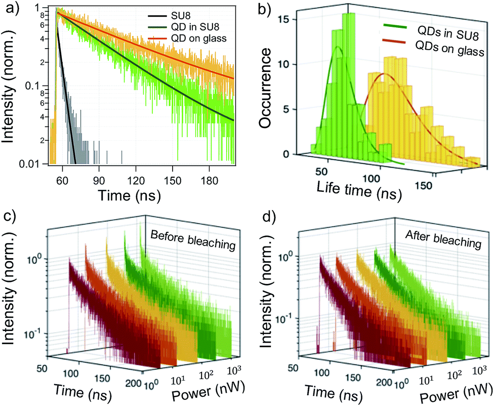 | ||
| Fig. 2 (a) The time-resolved PL decay of SU-8 (black), of a QD in SU-8 (green) and of a QD on a glass substrate (yellow) with the fitted lifetimes of 3.7 ± 0.15, 40.1 ± 0.23 and 65.2 ± 0.43 ns, respectively. (b) The lifetime statistics of individual QDs in SU-8 (green) and on the glass (yellow) with mean values of τin-SU8 = 45.2 ± 0.91, and τon-glass = 65.66 ± 2.12 ns, respectively. The dependence of PL radiative decay of a single QD in the SU-8 thin film on the excitation intensity before (c) and after (d) bleaching the fluorescence of SU-8. | ||
Again, the fluorescence of the SU-8 photoresist was observed during the lifetime measurement of a single QD. Indeed, since the effective volume of the focusing spot (diffraction limit) exciting the SU-8 photoresist is much larger than the actual volume of a single QD having a diameter of about 10 nm, the fluorescence signal of SU-8 appears as a sharp peak at the beginning of the PL decay of the QD, in particular with high excitation intensity (Fig. 2(c)). This sharp peak corresponds to a lifetime that fits well with the SU-8 lifetime (3.7 ± 0.15 ns), as shown in Fig. 2(a). To remove this background contribution from SU-8, higher excitation power was again used to photo-bleach the SU-8 fluorescence. Fig. 2(d) shows that the lifetime component of SU-8 is totally suppressed leaving the mono-exponential decay behavior of the single QD fluorescence. This result again confirms that the mixing of fluorescence issue of the host environment and the QDs is completely avoidable by photobleaching SU-8.
More interestingly, when considering only QDs on the glass substrate, the fluorescence lifetime tends to decrease with the excitation intensity, as shown in Fig. S3(a) (ESI†). This is explained by the higher contribution of the charged state fluorescence of single QDs.42 In strong contrast, the QDs embedded in SU-8 show a constant fluorescence lifetime versus the pumping power (the mean power ranges from nW to μW), as presented in Fig. S3(b) (ESI†) and in Fig. 2(c and d). This intensity independent lifetime results can be explained by the protection of the polymer material surrounding the QDs. The charged states, as well as the effects of oxidized QDs (discussed below), are minimized within the polymer matrices. Consequently, the fluorescence lifetime (τin-SU8) of the QDs remains the same for different pumping powers. This result contributes to the positive impacts of the SU-8 environment on QDs in short-term within the polymer nanocomposite.
To study the long-term effect of the photoresist on the colloidal CdSe/CdS QDs, the retained optical quality of the QDs embedded in SU-8 was investigated and compared to the optical quality of ones left in air (without SU-8) on glass cover-slips. Fig. 3(a) shows the fluorescence images (10 × 10 μm2) of QDs embedded in the SU-8 film and of bare QDs without SU-8. The fluorescence density of QDs in the two samples was daily examined by manually counting on different areas of 10 × 10 μm2 to study the fluorescence behavior of QDs. It is clear that the density of fluorescent QDs without SU-8 quickly reduced and disappeared from the fluorescence map after a course of 20 days (Fig. 3 (a – upper panel)). In strong contrast, QDs dispersed in SU-8 retained good quality with a quasi-constant number of bright QDs (Fig. 3 (a – lower panel)). For this experiment, two samples were stored in a dark place under ambient conditions. The fluorescence scans were performed at different areas for each day, and the statistic measurements as presented in Fig. 3(b) show fairly the trend of QD density versus time in SU-8, and without SU-8. In another experiment, two samples were stored under room light instead of the dark place to test the effect of photoradiation. We found that the disappearance of QDs without SU-8 becomes even more pronounced, as shown in Fig. 3(c). Specifically, within 5 days, most of the bare QDs lost their fluorescence properties, meanwhile, the ones embedded in SU-8 still had strong fluorescence. This result is consistent with the photo-oxidation and photo-bleaching of CdSe/ZnS QDs when comparing them in air and in nitrogen gas.12 It is clear that the presence of oxygen in the air is the main cause of the QDs becoming non-fluorescent. Indeed, due to the high number of dangling bonds, the oxidation process becomes easy to take place on the surface of QDs.13,43 This redox reaction turns a smooth crystalline shell into a defective shell with the formation of the respective oxide species as illustrated in Fig. 4(a and e). This oxidation effect is well-documented on bare CdSe QDs13,43,44 but little investigated on core/shell CdSe/CdS QDs. Despite the fact that the CdS shell helps to protect the core CdSe from oxidation in short-term, the oxygen diffusion gradually attacks the shell and consequently degrades the fluorescence properties of the QDs after a few days out of the solution. Fig. S4(c and d) (ESI†) presents schematically the energy diagram of core/shell QD structures with and without defects on the shell to illustrate the mechanism of fluorescence blinking and bleaching.
 | ||
| Fig. 3 (a – Upper panel) 100 μm2 fluorescence maps of bare CdSe/CdS without SU-8 spin-coated on the glass substrate. (a – Lower panel) 100 μm2 fluorescence maps of CdSe/CdS embedded in SU-8 and spin-coated on the glass substrate. The statistic density of QDs in air and in SU-8 on the same area of 100 μm2 when stored in a dark place (b) and stored under room light (c) for several days after the preparation. | ||
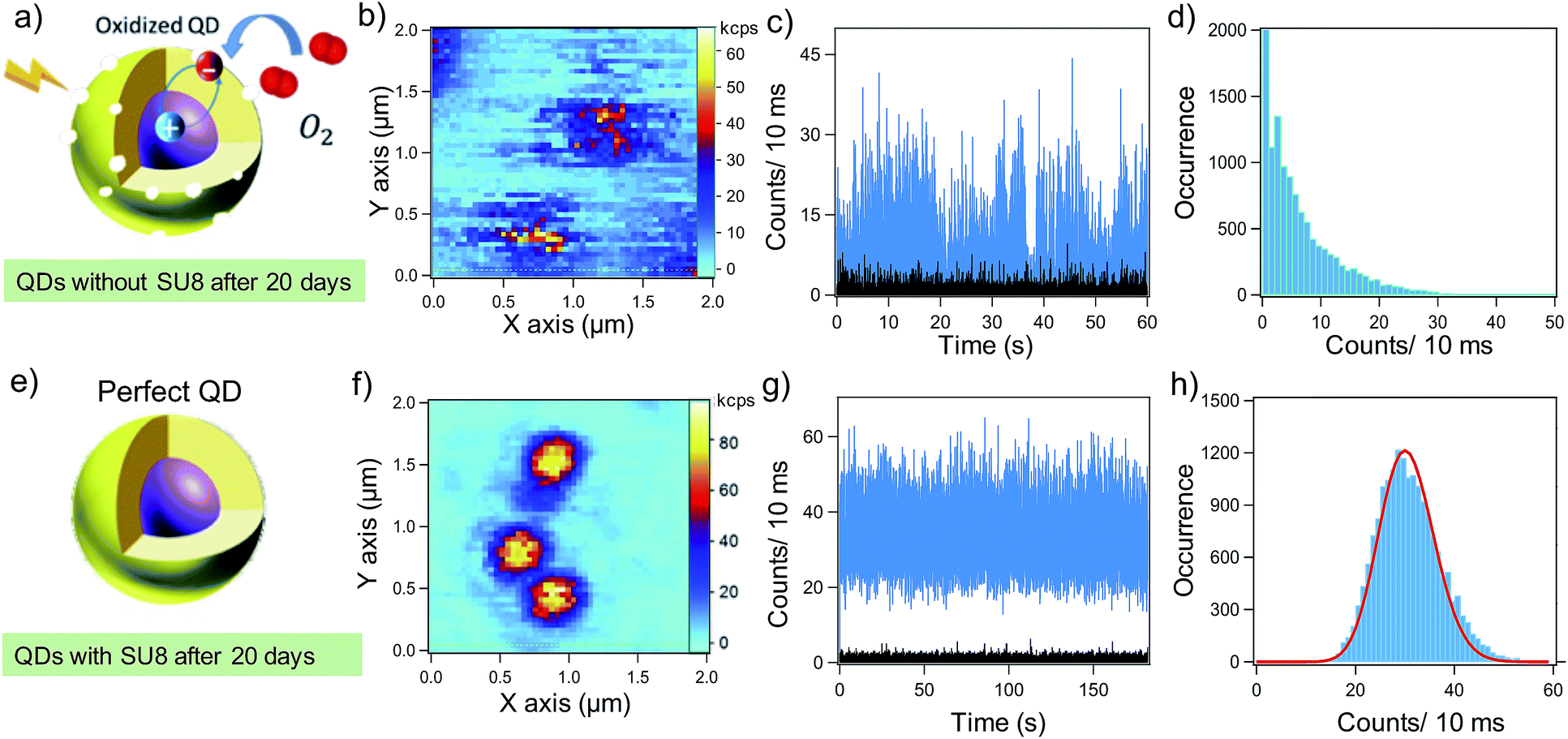 | ||
| Fig. 4 (a) Illustration of an oxidized (a) and a perfect (e) CdSe/CdS core/shell structure. (b) Fluorescence image of bare CdSe/CdS QDs without SU-8 after 20 days of preparation. (c) The fluorescence trajectory and (d) the intensity distribution corresponding to a single QD without SU-8 exposed to air. (f) Fluorescence image of CdSe/CdS QDs embedded in SU-8 after 20 days of preparation. (g) The fluorescence trajectory and (h) the intensity distribution corresponding to a single QD in the SU-8 photoresist. | ||
Fig. 4 shows the comparison between the fluorescence behavior of QDs without SU-8 and with SU-8 after 20 days under ambient conditions. In the presence of defect modes and surface trapping states, the fluorescence of single QDs is no longer stable (Fig. 4(b)). The switching between the bright state and dark state is confirmed by fluorescence intensity trace and distribution (Fig. 4(c and d)). The QD spends a little time in the bright state and exhibits fast flickering. This process becomes more efficient via photo-radiation (bright area) where the flow of e–h exchanges frequently in the core/shell structure during the excitation, radiative recombination, and fast Auger processes. Consequently, the blinking behavior becomes more pronounced and finally, the quenching of QD fluorescence occurs. In strong contrast, the QDs inside polymer matrices are observed to better retain the high quality of optical properties with a low possibility of nonradiative effects. The fluorescence intensity trajectory of a single QD (Fig. 4(g)) exhibits very low blinking on the 10 ms time scale. The intensity histogram with a single peak is well-fitted by a Poisson distribution with a standard deviation of 5.8, very close to the standard deviation of the experimental data which is equal to 7 (Fig. 4(h)). It is clear that the incorporation of QDs into the SU-8 photoresist helps to prevent the oxidation effect and allows keeping the good quality of fluorescence properties. Moreover, it is well-known that SU-8 is a common material used for the fabrication of photonic structures. This nanocomposite has, therefore, excellent accessibility for the fabrication of photonic structures containing QDs in order to optimize and manipulate the single photon emission.45
By using the LOPA-based DLW technique, we present the micro-fabrication on the synthesized CdSe/CdS/SU-8 nanocomposite and a fluorescence enhancement of an embedded QD in a simple pillar structure. We tuned the concentration of QDs in the material to adjust the microscale interdot-spacing between QDs for various applications of the fabricated structures. For example, with a highly concentrated nanocomposite, polymeric structures containing multiple QDs are easily fabricated without determination of QD location. Fig. 5(a and b) demonstrate the micro-ring structure fabricated from a high concentration of the QD composite. The bright ring (Fig. 5(b)) represents the fluorescence of QDs embedded in the SU-8 polymer. Meanwhile, with a nanomolar concentration, a single QD is demonstrated to be embedded in the desired position within polymeric multi-dimensional photonic structures thanks to the flexibility of LOPA-based DLW.39,40Fig. 5(c) shows the insertion of a single CdSe/CdS QD into a pillar array structure as an example of an embedded single photon emitter into the polymeric pattern. The pillar has a radius of 150 nm and a height of 1 μm. The fluorescence image (Fig. 5(d)) of the corresponding structure indicates the position of the QD (bright spot) at the central pillar. The embedding precision is fully controlled on the nanoscale by using the integrated optical confocal set-up.
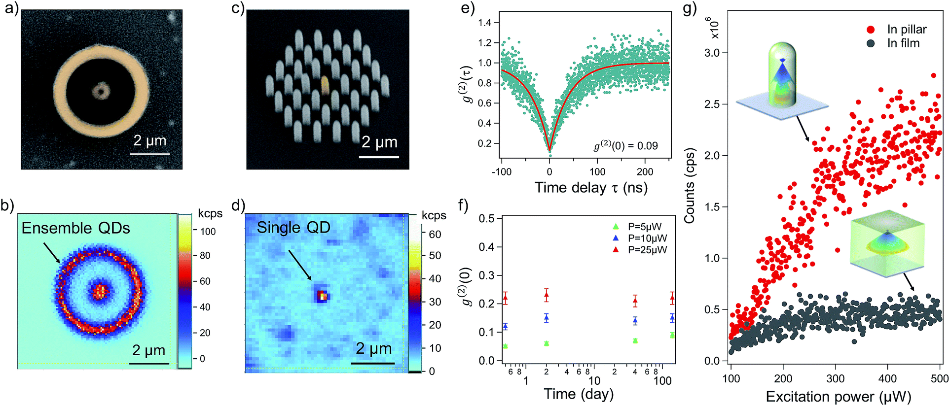 | ||
| Fig. 5 (a) Colorized SEM image of a micro-ring with a central dot structure fabricated with a high concentration of QDs in the nanocomposite. The colorized part depicts the structures with embedded QDs. (b) Fluorescence image of the micro-ring containing the ensemble of CdSe/CdS QDs corresponding to the structure (a). (c) Colorized SEM image of pillar structures fabricated with a low concentration of the nanocomposite to embed a single QD in the central pillar. (d) Fluorescence image of the pillar structure corresponding to the structure (d). The bright spot indicates the location of the embedded QD in the center of the structure. (e) Antibunching curve of the single CdSe/CdS QD corresponding to the one embedded in the pillar structure, with g(2)(0) = 0.09 ± 0.004 at a pumping power of 5 μW. (f) The dependence of g(2)(0) on excitation powers and different time durations after fabrication. (g) Comparison of the emission flux of a single QD embedded in the SU-8 film and pillar as a function of excitation power. The subset figure depicts the radiation pattern (transverse magnetic polarized light – TM mode) of the QD in the corresponding film and pillar. | ||
The single photon emission of the coupled QD was then characterized by using the autocorrelation function g(2)(τ). Fig. 5(e) shows the antibunching curve obtained from the QD embedded in a single pillar structure with g(2)(0) = 0.09 ± 0.004 at a pumping power of 5 μW. The photo-corrosion and oxidation of the QDs are now prevented by the surrounding polymer, which helps the QDs retain their optical characteristics. Moreover, the chemical resistant properties of the cured SU-8 also offer long-term preservation of single photon sources in coupling devices. Fig. 5(f) shows the maintenance of single photon quality of the embedded QDs after more than 100 days. In particular, regarding the single photon emission (g(2)(0) ≤ 0.5), we excited the coupled QDs at three low excitation power values (5, 10 and 25 μW). Comparing the value of g(2)(0) right after fabrication and after several days, the results appear stable at 0.08 ± 0.001, 0.14 ± 0.02 and 0.22 ± 0.025 for different pumping powers of 5, 10 and 25 μW, respectively. These results clearly confirm the positive influence of SU-8 on the single photon emission maintained in polymeric photonic structures. Consequently, the device can be reusable for further characterization.
With such a simple geometry of submicron pillars,36,48,49 we particularly demonstrate the fluorescence enhancement of a single QD embedded into the polymeric structure. Fig. 5(g) shows the emission rate of a single QD coupled in the SU-8 film (black dots) and in an SU-8 pillar (red dots) as a function of the excitation power. In the film, the single QD emits from 100 thousand counts per second (kcps) to a saturated value of nearly 500 kcps. Meanwhile, the emission rate of the coupled QD in a pillar significantly increases to a saturated value of over 2 million cps with continuous excitation at 532 nm. The emission enhancement reaches an increase of around 4-fold as a result of the shaping radiation pattern in the pillar structure.36,48,49 This experimental result was confirmed by numerical calculations using the finite-difference time-domain method (FDTD-Lumerical). The insets of Fig. 5(g) show the calculated angular emission pattern of a single QD in the film and in a pillar (for TM mode). In the film, the angular radiation pattern of TM mode strongly diverges out of the half-angle (58.1°) of the used objective lens having NA = 1.3 (see Fig. S5 in the ESI†). In contrast, due to the geometry of the pillar, the TM angular radiation pattern of the single QD is shaped into a low divergent profile where a large portion of the pattern is captured within the objective lens. Hence, the collection efficiency of the embedded QD is significantly improved. We note that the SU8 pillars around the central one do not have an influence on the fluorescence of the QD located in the central pillar. The distance between pillars is relatively large to possess a photonic bandgap effect at the fluorescence wavelength of the used QD. Nonetheless, due to the low refractive index contrast (nSU8 = 1.6, nglass = 1.52), the coupling (weak or strong) of the QDs with polymeric structures requires a strict optimization of the cavity factor, which is under further investigation. Also, the coupling of a single emitter to a single polymeric pillar realized by the LOPA direct laser writing presents a great advantage compared to previous similar studies,48,49 because the single QD could be added into the pillar at any desired position, which will be optimum for the coupling.
Conclusion
In conclusion, we have demonstrated that by embedding colloidal semiconductor CdSe/CdS core/shell nanoparticles into an SU-8 photoresist, we obtain the high-quality QD–polymer nanocomposite, which offers not only the long-term preservation of such colloidal QDs but also the accessibility to the fabrication of polymeric photonic structures. Due to the high chemical compatibility, the QDs inside the polymer are shown to better retain their optical properties without any damage by oxidation processes. By tuning the concentration level of QDs in polymer matrices, multiple QDs or a single QD was inserted into the polymeric devices by an LOPA DLW technique. At the single molecule level, the fluorescence of SU-8 is proved to be negligible and does not deteriorate the single photon generation of the individual QDs. The chemical resistance of cured SU-8 not only contributes to the maintenance of QDs inside structures after fabrication but also makes the device reusable. With a simple geometry of a pillar structure, we demonstrated a strong enhancement of QD fluorescence. These results are particularly important and promising for further coupling to devices since this approach is easy to implement under ambient conditions. Further efforts will be devoted to investigating photonic devices that exhibit photonic effects in terms of quantum confinement and efficient light harvesting capabilities such as micro-cavities and three-dimensional photonic structures.Experimental
Elaboration of the colloidal CdSe/CdS–SU8 nanocomposite
The colloidal CdSe/CdS QDs were synthesized by the isotropic and epitaxial growth of a thick CdS layer (5 nm) on a 2.5 nm-diameter CdSe core as described in ref. 37. The QDs with an average diameter of 13 nm diluted in hexane/octane (ratio 9/1) were exchanged to a toluene solution which enables their mixing with the SU-8 monomer. The QDs in toluene at a low concentration were injected gradually into SU-8 with constant stirring. Note that with a high concentration of QDs, it is difficult to obtain mono-dispersion of CdSe/CdS QDs in the polymer material but rather the dispersion of clusters is obtained. The mixed solution was kept stirring for 4 hours to obtain a homogeneous distribution of QDs as well as to evaporate the toluene solution giving the QD/SU-8 nanocomposite the initial SU-8 viscosity level. After preparation, the nanocomposite was spin-coated on glass substrates to perform optical characterization.Single photon measurement
The single photon emission was characterized using the time statistics of the photons on a short time scale through a second-order intensity correlation function defined as: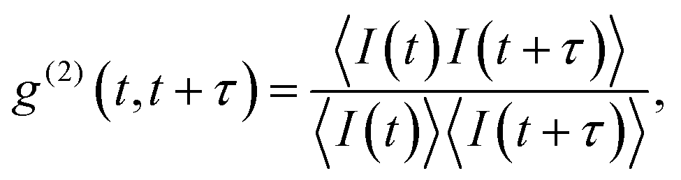 | (1) |
 8,46 with the time delay τ and an average lifetime τ0 (the lifetime is the asymptotic value reached at zero pumping).
Fabrication of coupled QDs/polymeric structures
The LOPA-based DLW technique35,39 was used to fabricate polymeric structures. A continuous-wave green laser (CW-532 nm) with controlled power is tightly focused into the sample by using an objective lens having a numerical aperture of 1.3 (oil immersion). The sample is mounted in a three-dimensional piezoelectric translation system, which allows realizing the arbitrary structure on demand. The feature size of the structures is controlled by finely adjusting the exposure dose, i.e. laser power or exposure time. The samples were prepared as explained above followed by a standard soft-baking step before fabrication. Note that, thanks to the optical-thermal induced polymerization effect47 at the focusing spot, after the light exposure, a solid structure is obtained without the post-exposure baking.To embed a single QD into a polymeric structure, the fabrication procedure consists of 3 main steps: (1) positioning the location of individual QDs using low laser power (a few μW), (2) fabricating structures by the optical-thermal induced polymerization around the pre-defined QD using high power of the same laser (a few mW), and (3) developing structures to remove the unpatterned area using a standard SU-8 developer (MicroChem). The fabricated structures are then ready for further characterization.
Conflicts of interest
There are no conflicts to declare.Acknowledgements
This work is supported by a public grant overseen by the French National Research Agency (ANR) as part of the “Investissements d'Avenir” program (Labex NanoSaclay, reference: ANR-10-LABX-0035).Notes and references
- L. Damalakiene, V. Karabanovas, S. Bagdonas and R. Rotomskis, Int. J. Mol. Sci., 2016, 17, 473 CrossRef.
- S.-E. Stiriba, H. Frey and R. Haag, Angew. Chem., 2002, 41, 1329–1334 CrossRef CAS.
- P. Alivisatos, Nat. Biotechnol., 2004, 22, 47–52 CrossRef CAS.
- M.-X. Zhao and B.-J. Zhu, Nanoscale Res. Lett., 2016, 11, 207 CrossRef.
- I. Robel, V. Subramanian, M. Kuno and P. V. Kamat, J. Am. Chem. Soc., 2006, 128, 2385–2393 CrossRef CAS.
- B. Sun, E. Marx and N. C. Greenham, Nano Lett., 2003, 3, 961–963 CrossRef CAS.
- M. K. Choi, J. Yang, T. Hyeon and D.-H. Kim, npj Flexible Electronics, 2018, 2, 10 CrossRef.
- B. Lounis, H. A. Bechtel, D. Gerion, P. Alivisatos and W. E. Moerner, Chem. Phys. Lett., 2000, 329, 399–404 CrossRef CAS.
- J. L. O'Brien, A. Furusawa and J. Vuckovic, Nat. Photonics, 2009, 3, 687–695 CrossRef.
- N. Gisin, G. Ribordy, W. Tittel and H. Zbinden, Rev. Mod. Phys., 2002, 74, 145–195 CrossRef.
- C. Galland, Y. Ghosh, A. Steinbruck, M. Sykora, J. A. Hollingsworth, V. I. Klimov and H. Htoon, Nature, 2011, 479, 203–207 CrossRef CAS.
- W. G. J. H. M. van Sark, P. L. T. M. Frederix, D. J. Van den Heuvel, H. C. Gerritsen, A. A. Bol, J. N. J. van Lingen, C. de Mello Donega and A. Meijerink, J. Phys. Chem. B, 2001, 105, 8281–8284 CrossRef CAS.
- D. A. Hines, M. A. Becker and P. V. Kamat, J. Phys. Chem. C, 2012, 116, 13452–13457 CrossRef CAS.
- S. Rosen, O. Schwartz and D. Oron, Phys. Rev. Lett., 2010, 104, 157404 CrossRef PubMed.
- T. Pellegrino, L. Manna, S. Kudera, T. Liedl, D. Koktysh, A. L. Rogach, S. Keller, J. Radler, G. Natile and W. J. Parak, Nano Lett., 2004, 4, 703–707 CrossRef CAS.
- S. Wei, Z. Zhu, Z. Wang, G. Wei, P. Wang, H. Li, Z. Hua and Z. Lin, Mater. Res. Express, 2016, 3, 075904 CrossRef.
- S.-K. Park, X. Teng, J. Jung, P. Prabhakaran, C. W. Ha and K.-S. Lee, Opt. Mater. Express, 2017, 7, 2440–2449 CrossRef CAS.
- S. Cho, J. Kwag, S. Jeong, Y. Baek and S. Kim, Chem. Mater., 2013, 25, 1071–1077 CrossRef CAS.
- M. Vasileiadis, I. Koutselas, S. Pispas and N. A. Vainos, J. Polym. Sci., Part B: Polym. Phys., 2015, 54, 552–560 CrossRef.
- J. Aldana, Y. A. Wang and X. Peng, J. Am. Chem. Soc., 2001, 123, 8844–8850 CrossRef CAS.
- K.-S. Lee, P. Prabhakaran, K. K. Jang, J.-J. Park, D.-Y. Yang and Y. Son, Embedding silver nanoparticles or quantum dots in photonic structures|SPIE Newsroom, 2011 Search PubMed.
- W. G. J. H. M. v. Sark, P. L. T. M. Frederix, A. A. Bol, H. C. Gerritsen and A. Meijerink, ChemPhysChem, 2002, 3, 871–879 CrossRef.
- J.-P. Merkl, C. Wolter, S. Flessau, C. Schmidtke, J. Ostermann, A. Feld, A. Mews and H. Weller, Nanoscale, 2016, 8, 7402–7407 RSC.
- H. Zang, P. K. Routh, Q. Meng and M. Cotlet, Nanoscale, 2017, 9, 14664–14671 RSC.
- N. Al-Attar, E. Kennedy, G. Kelly and J. H. Rice, J. Phys. Chem. C, 2015, 119, 6278–6287 CrossRef CAS.
- H. Leng, J. Loy, V. Amin, E. A. Weiss and M. Pelton, ACS Energy Letters, 2016, 1, 9–15 CrossRef CAS.
- H. Zang, P. K. Routh, Y. Huang, J.-S. Chen, E. Sutter, P. Sutter and M. Cotlet, ACS Nano, 2016, 10, 4790–4796 CrossRef CAS.
- Y. A. Gromova, A. O. Orlova, V. G. Maslov, A. V. Fedorov and A. V. Baranov, Nanoscale Res. Lett., 2013, 8, 452 CrossRef PubMed.
- A. Qualtieri, L. Martiradonna, T. Stomeo, M. T. Todaro, R. Cingolani and M. D. Vittorio, Microelectron. Eng., 2009, 86, 1127–1130 CrossRef CAS.
- L. Martiradonna, T. Stomeo, L. Carbone, G. Morello, A. Salhi, M. D. Giorgi, R. Cingolani and M. D. Vittorio, Phys. Status Solidi B, 2006, 243, 3972–3975 CrossRef CAS.
- H. Gordillo, I. Suarez, R. Abargues, P. Rodriguez-Canto, S. Albert and J. P. Martinez-Pastor, J. Nanomater., 2012, 2012, 33 Search PubMed.
- E. Moreau, I. Robert, J. M. Gerard, I. Abram, L. Manin and V. Thierry-Mieg, Appl. Phys. Lett., 2001, 79, 2865–2867 CrossRef CAS.
- K. Hennessy, A. Badolato, M. Winger, D. Gerace, M. Atature, S. Gulde, S. Falt, E. L. Hu and A. Imamoglu, Nature, 2007, 445, 896–899 CrossRef CAS.
- T. Yoshie, A. Scherer, J. Hendrickson, G. Khitrova, H. M. Gibbs, G. Rupper, C. Ell, O. B. Shchekin and D. G. Deppe, Nature, 2004, 432, 200–203 CrossRef CAS.
- F. Mao, Q. C. Tong, D. T. T. Nguyen, T. H. Au, R. Odessey, F. Saudrais and N. D. Lai, Proc. SPIE, 2017, 1011509 Search PubMed.
- D. T. T. Nguyen, T. H. Au, Q. C. Tong, M. H. Luong, A. Pelissier, K. Montes, H. M. Ngo, M. T. Do, D. B. Do, D. T. Trinh, T. H. Nguyen, B. Palpant, C. C. Hsu, I. Ledoux-Rak and N. D. Lai, Journal of Science: Advanced Materials and Devices, 2016, 1, 18–30 Search PubMed.
- B. Mahler, P. Spinicelli, S. Buil, X. Quelin, J.-P. Hermier and B. Dubertret, Nat. Mater., 2008, 7, 659–664 CrossRef CAS.
- T. H. Au, S. Buil, X. Quelin, J.-P. Hermier and N. D. Lai, Appl. Phys. Lett., 2018, 113, 111105 CrossRef.
- M. T. Do, T. T. N. Nguyen, Q. Li, H. Benisty, I. Ledoux-Rak and N. D. Lai, Opt. Express, 2013, 21, 20964–20973 CrossRef.
- T. Au, D. Trinh, Q. Tong, D. Do, D. Nguyen, M.-H. Phan, N. Lai, T. H. Au, D. T. Trinh, Q. C. Tong, D. B. Do, D. P. Nguyen, M.-H. Phan and N. D. Lai, Nanomaterials, 2017, 7, 105 CrossRef PubMed.
- M. Zhu, J. Zhou, Z. Hu, H. Qin and X. Peng, ACS Photonics, 2018, 5(10), 4139–4146 CrossRef CAS.
- P. Spinicelli, S. Buil, X. Quelin, B. Mahler, B. Dubertret and J.-P. Hermier, Phys. Rev. Lett., 2009, 102, 136801 CrossRef CAS.
- N. A. Eom, T.-S. Kim, Y.-H. Choa, W.-B. Kim and B. S. Kim, J. Nanosci. Nanotechnol., 2014, 14, 8024–8027 CrossRef CAS.
- L. Liu, Q. Peng and Y. Li, Inorg. Chem., 2008, 47, 3182–3187 CrossRef CAS.
- P. Senellart, G. Solomon and A. White, Nat. Nanotechnol., 2017, 12, 1026–1039 CrossRef CAS PubMed.
- G. Messin, J. P. Hermier, E. Giacobino, P. Desbiolles and M. Dahan, Opt. Lett., 2001, 26, 1891–1893 CrossRef CAS.
- D. T. T. Nguyen, Q. C. Tong, I. Ledoux-Rak and N. D. Lai, J. Appl. Phys., 2016, 119, 013101 CrossRef.
- A. Dousse, L. Lanco, J. Suffczynski, E. Semenova, A. Miard, A. Lemaitre, I. Sagnes, C. Roblin, J. Bloch and P. Senellart, Phys. Rev. Lett., 2008, 101, 267404 CrossRef CAS.
- T. M. Babinec, B. J. M. Hausmann, M. Khan, Y. Zhang, J. R. Maze, P. R. Hemmer and M. Loncar, Nat. Nanotechnol., 2010, 5, 195–199 CrossRef CAS.
Footnote |
| † Electronic supplementary information (ESI) available. See DOI: 10.1039/c9na00411d |
| This journal is © The Royal Society of Chemistry 2019 |