 Open Access Article
A solvent-free porous liquid comprising hollow nanorod–polymer surfactant conjugates†
Raj
Kumar‡
,
Prabhu
Dhasaiyan‡
 ,
Parinamipura M.
Naveenkumar
and
Kamendra P.
Sharma
 *
*
Department of Chemistry, Indian Institute of Technology Bombay, Mumbai-400076, India. E-mail: k.sharma@chem.iitb.ac.in
First published on 3rd September 2019
Abstract
Liquids having permanent porosity can offer significant processing advantages over their solid counterparts. This has recently led to tremendous activity towards the design and development of intrinsic pores in the liquid phase, predominantly for studies involving gas sequestration. We show here the development of a solvent-free mesoporous liquid material based on anisotropic “hollow-core and silica-shell” nanorods conjugated with polymer surfactant chains, which can sequester CO2 gaseous molecules at 0 °C. Hollow silica nanorods (SiNRs) with average aspect ratios of 2.5, 8, and 11 (as obtained by transmission electron microscopy (TEM) and small angle X-ray scattering) were synthesized using a surfactant-templating methodology, and fluidity/flow processability were imparted by a three-step process involving covalent coupling of an organosilane (OS) canopy to form OS@SiNR, followed by electrostatic grafting of polymer surfactant (PS) chains to the organosilane, and subsequent removal of solvent to provide a solvent-free composite, PS-OS@SiNR. Differential scanning calorimetric and frequency sweep rheological measurements of PS-OS@SiNR indicated melting transition between 15 and 20 °C, while thermal gravimetric analysis showed ca. 20 w/w% silica content (i.e. 9.5% volume fraction of silica and containing ca. 3% volume fraction as voids). As observed using TEM, the surface modification of the nanorods resulting in the formation of PS-OS@SiNR does not lead to blockage of the hollow core. We show that whilst N2 adsorption in the porous liquid is hindered due to the glassy polymer-surfactant layer at −196 °C, CO2 adsorption at 0 °C showed 3.3–4.8 w/w% gas uptake. Overall we demonstrate the synthesis of an anisotropic porous liquid which not only sequesters CO2 but also has the ability to flow like a liquid.
1. Introduction
Porosity is an important property to be considered during the design and development of advanced multifunctional materials. This is a result of the broad application range of porous materials that find usage in drug delivery, gas separation, catalysis, biosensing, etc. In terms of the length scales, porosity can be of the order of <2 nm (microporous), 2–50 nm (mesoporous), and >50 nm (macroporous). Natural microporous materials include clay, zeolite, charcoal etc. and these have found tremendous use in drug delivery applications. For the past several decades, there has been continuous upsurge of interest towards developing porous materials for the uptake of gases, catalysis, use in energy storage materials etc.1,2 The majority of these porous materials are microporous, solid, and range from amorphous (e.g. porous carbons) to highly crystalline (e.g. metal–organic frameworks; MOFs),3–11 as well as discrete molecules.12–14 Although solid porous materials exhibit a low energy penalty towards gas adsorption–desorption cycles, the solid phase itself imparts inherent limitations towards implementation of such materials in conventional flow related processes.15 Moreover, the porous solids need packaging in cartridges/columns which makes them unsustainable with a heavy environmental footprint. In order to alleviate these problems, porosity in the liquid phase is desirable. Achieving permanent porosity in the liquid phase can result in porous liquids which when compared with their solid counterparts can have advantages related to processing. For instance, these can be smeared or coated onto surfaces to make thin films and provide a continuous stream in pipes thus resulting in faster diffusion and exchange kinetics of the sequestered gaseous molecules. Therefore, porous liquids can combine the porous property and liquid-like flowing behaviour for developing next generation multifunctional materials.15,16 Further, it can be envisaged that the combination of porosity–fluidity in a zero vapour pressure solvent environment can offer great scientific and technological opportunities for the future.However, porosity in conventional liquids is transient and the associated length scales are extremely small, of the order of 0.1 to 0.4 Å.17 Therefore, research for design and development of liquids with permanent empty pores is continually flourishing.18,19 Recently, Cooper et al. reported the synthesis of porous liquids with permanent pores between ∼1 and 3 Å based on the synthesis of crown-ether cages dispersed in a crown ether (15-crown-5) solvent that cannot enter the cages.15 The same group also developed a quantitative understanding on gas occupancy (∼75%) and diffusion in these crown ether based porous liquids, and demonstrated the reversibility in gas separation processes. More recently, Coudert et al. showed using a combination of X-ray/neutron scattering and molecular dynamics simulations the formation of a metal organic framework (MOF) liquid with pore sizes of ∼5 Å based on the melting of a zeolitic imidazole framework at ∼2000 °C. Their study revealed the retention of chemical configuration, coordinative bonding and porosity of the MOF in the liquid state.20
The above examples show permanent pores/cavities in a liquid state residing in the form of micropores (i.e. below 2 nm), achieved by using either molecular crown-ether cages dispersed in a solvent (which is larger than the cage cavities) or relatively larger MOFs at higher temperatures. However, for meso-/nano-pores (2–50 nm) the object/particle size would be commensurate with the size of the pore. Also, the interaction-potential for meso-/nano-scale objects varies significantly from the typical Lennard-Jones pair potential for small molecules. As a result, the length scale associated with the interacting force field is significantly shorter than the size of the meso-/nano-object itself. Therefore a liquid or molten like state for pure mesoscale objects is usually not accessible.21 This was first demonstrated by the classical studies of Frenkel and co-workers on C60 molecules.22 Using computer simulations they plotted a phase diagram of C60 which demonstrated the liquid vapour critical point to be approximately 45 K lower than the sublimation line, suggesting the non-attainment of a liquid phase in C60. A similar understanding can be applied for inorganic nanoparticles and quantum dots for not attaining a liquid phase, but rather undergoing sintering after subjecting the system to very higher temperatures. Giannelis and co-workers circumvented the above problem by using polymers with melting points close to room temperature, and grafting them to the surface of nanoparticles for making hybrid nanoscale liquids, which can flow in the absence of any solvent.23–26 With the same approach Giannelis et al. prepared a variety of liquid like materials extending their utility for biomaterials.27–29 Based on this idea Dai et al. reported the preparation of liquids with mesoporosity (2–50 nm) by electrostatic grafting of polymers on the surface of hollow and spherical silica nanoparticles via a core–corona–canopy approach.19 The hollow pores could be utilized for gas adsorption and exchange. However, reports on making porous liquids based on anisotropic (directionally dependent) cylindrical mesopores are still limited. Porous liquids made using anisotropic nanoparticles can be extremely advantageous over their spherical counterparts, simply due to the morphology of the nanoparticles. It is well known in the literature that polydisperse nanospheres can fill space easily and therefore have a higher percolation threshold volume fraction. Comparatively, nanorods can form a connecting network by percolating at much lower volume fractions, resulting in an easier network formation and gelation.30 This property of nanorods can have interesting implications in flow-related processes as the viscosity of the porous liquids made using nanorods can be tuned by changing the nanorods’ aspect ratio, packing fraction, and the attraction potential. Moreover, the dependence of adsorption on the aspect ratio of nanorods has not been investigated.
In this work, we show the development of another class of mesoporous liquid materials based on anisotropic “hollow-core and silica-shell” nanorods (SiNRs). Hollow silica nanorods with different aspect ratios (2.5, 8, and 11) were synthesized using surfactant-templating methodology and thoroughly characterized using small angle X-ray scattering (SAXs) and transmission electron microscopy (TEM) for size analysis, and BET for gas adsorption analysis. These rods were subsequently used to synthesize a solvent-free porous liquid via a three-step process involving covalent coupling of an organosilane (OS) canopy to form OS@SiNR, followed by electrostatic grafting of polymer surfactant (PS) chains to the organosilane, and finally the removal of solvent to provide the solvent-free composite materials PS-OS@SiNR-2.5, 8 and 11. Differential scanning calorimetry and frequency sweep rheological measurements indicated melting transition of all PS-OS@SiNR samples in the range of 15–20 °C. The cryo-TEM of PS-OS@SiNR showed porous rods with an overall pore fraction of 3%. As observed using TEM and CO2 gas adsorption, the surface modification of the nanorods leading to the formation of PS-OS@SiNR did not lead to blockage of the intrinsic pores. Gas adsorption measurements at 0 °C using CO2 as the adsorbate showed 3.3–4.8% w/w gas uptake.
2. Experimental section
(a) Materials
Brij® 58 (average Mn ∼ 1124; P5884), cyclohexane (227048), diethylamine (471216), tetraethyl orthosilicate (TEOS; 131903), dimethyloctadecyl[3-(trimethoxysilyl)propyl]ammonium chloride (435708), and poly(ethylene glycol) 4-nonylphenyl 3-sulfopropyl ether potassium salt (473197; polymer surfactant, PS) were all purchased from Sigma-Aldrich and used as such. NiCl2.6H2O, NaOH, HCl, tetrahydrofuran (THF), isopropyl alcohol (IPA), and toluene were all purchased from Merck India and used as received without any further purification. All solvents used for the entire experiments were of analytical grade (AR). Milli-Q water with a resistivity of 18.2 MΩ cm−1 was used for all the experimental procedures.(b) Instrumentation and characterization
Poly core–shell cylindrical model: This model calculates scattering from a polydisperse (log-normal distribution) sample of cylindrical rods with a core–shell like scattering length density (SLD). The final intensity is obtained in the form of weighted normalized distribution of scattering from each rod of different size. The core in the hollow rods can be considered to be filled with solvent in the case of an aqueous dispersion or air in the case of a porous liquid.
where Vs and Vc are the volumes of the shell and core, respectively. θ is the angle between the cylindrical axis and the scattering vector, q, and J1(x) is the first order Bessel function. All possible orientations of the rod w.r.t q are averaged in the form factor, F2 (q, θ), data. The core radius = R, core length = L, shell length = L + 2T, and shell radius = R + T, where T = shell thickness. ρc, ρs and ρsolv are the SLD of the core, shell and solvent, respectively.
The apparent structure factor (Sapp(q); as given below) in the PS-OS@SiNR samples can be extracted by dividing the scattering from the PS-OS@SiNR with the form factor of the dilute aqueous solution of the corresponding nanorods multiplied by the inverse of volume fractions (φ) of rods in composite and dilute samples, respectively.
(c) Methods for the preparation of the porous liquid
The preparation was carried out in two steps:3. Results and discussion
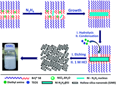
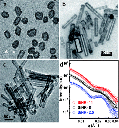
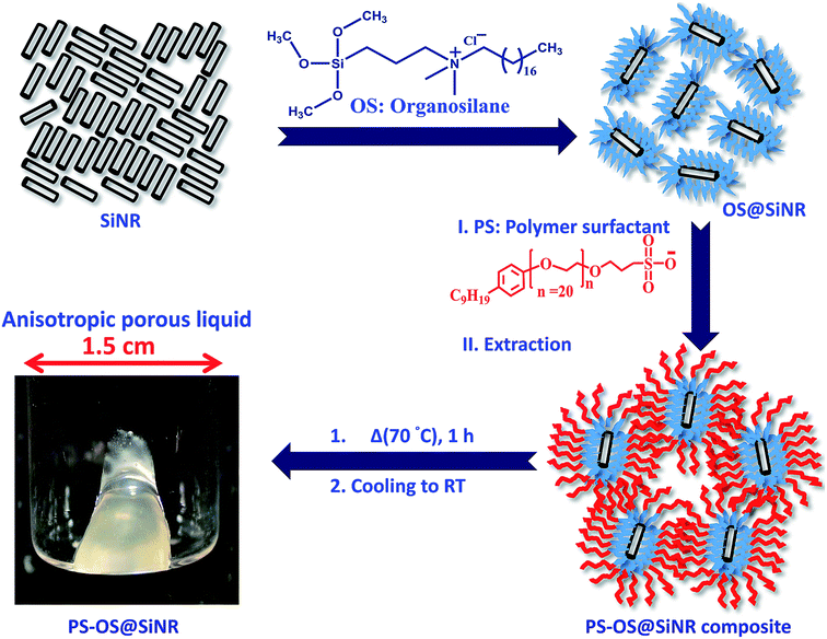
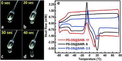
Hollow silica nanorods were synthesized according to the reverse micelle template-assisted methodology shown in Fig. 1.31 Briefly, silica nanorods having three different aspect ratios were synthesized by varying the ratio of NiCl2/N2H4 and Brij® 58 surfactant. Selective etching (removal) of nickel hydrazine from the Ni–N2H4@Si complex with 1 M HCl resulted in hollow silica nanorods (henceforth mentioned as SiNRs (the detailed synthesis procedure is given in the Experimental section). The transmission electron microscopy (TEM) images of all three samples showed a hollow core with a silica shell. The aspect ratio from the TEM images provided values of 2.5 ± 1.2, 8.3 ± 3.5, and 11.4 ± 2.7 (based on size averaging of ≈150 particles (Fig. 2a–c)). Further, to obtain statistically relevant information on the size of the nanorods viz. the aspect ratios, small angle X-ray scattering (SAXs) characterization on 0.1 w/w% dispersion of SiNRs in ethanolic solution was performed. The modelling and analysis of the SAXs data were performed using a polydisperse core–shell cylinder model which provided approximate aspect ratios of 1.3, 6.6 and 7.5 (Fig. 2d; see ESI Table S2†). This significant deviation of SAXs results from TEM was not surprising as SAXs provides data from statistically relevant population in the form of 〈L〉/〈R〉 (where 〈 〉 represent ensemble averaging, L = length, R = radius). However, based on TEM observations the rod samples with three different aspect ratios were named SiNRs 2.5, 8, and 11. The surface area/average pore size of the mesopores in SiNRs was obtained using the Brunauer–Emmett–Teller (BET)/Barrett–Joyner–Halenda (BJH) method applied on the N2 adsorption isotherms taken at −196 °C, which provided values of 127 m2 g−1/37.1 Å, 143 m2 g−1/37.3 Å, and 196 m2 g−1/88 Å for aspect ratios 2.5, 8 and 11, respectively. The FT-IR spectra of the SiNRs showed typical vibrational bands of silica at 796, 957, and 1095 cm−1 suggesting the formation of an extended silica network from the precursor (ESI Fig. S1a–c† red FT-IR spectra).32The synthesis of the anisotropic porous liquid was achieved via a three-step process involving (a) covalent conjugation of organosilane (OS; dimethyloctadecyl[3-(trimethoxysilyl)propyl]ammonium chloride) to form a coronal layer on the surface of bare and hollow silica nanorods (OS@SiNR), (b) electrostatic coupling with a polymer surfactant (PS; 4-nonylphenyl 3-sulfopropyl ether potassium salt) (Fig. 3) to form a canopy similar to that reported in the literature,19 followed by extraction of excess PS by toluene and (c) finally heating the system for 1 h at 70 °C under low pressure conditions to form the solvent-free composite (henceforth mentioned as PS-OS@SiNR), which was stored in a desiccator after drying under vacuum, prior to analysis. The sequential synthesis steps were characterized using a combination of transmission electron microscopy (TEM), Fourier-transform infra-red spectroscopy (FTIR), small angle X-ray scattering (SAXs), thermogravimetric analysis (TGA), and differential scanning calorimetry (DSC). After covalent coupling of organosilane (OS) on the surface of the anisotropic rods (OS@SiNR), TEM indicated retention of the rod like structure and the porous/hollow core in all three samples with different aspect ratios (ESI Fig. S2a–c†). It was observed that the aspect ratios did not change significantly after the OS coupling to the bare SiNRs (ESI Fig. S2a–c†). FT-IR of OS@SiNRs (A.R 2.5, 8 and 11) exhibited clear bands corresponding to the stretching and bending vibrations of alkane moieties at 2929, 2854, and 1471 cm−1, respectively, which were in agreement with the literature (ESI Fig. S1a–c†).19 The increase of peak amplitude around 1062 cm−1 arising due to the Si–O–Si bond was a result of OS chemical modification of bare SiNRs and was consistent with literature reports.19 All the composite samples, i.e. PS-OS@SiNR-2.5, 8, and 11, obtained by electrostatic interaction of the anionic polymer surfactant with OS@SiNR showed a soft-gel like appearance at close to room temperature (Fig. 3). However, heating further to 35 °C resulted in flow under the influence of gravity (Fig. 4a–d). Therefore to understand the different phase transitions associated with these composite samples, they were further characterized using differential scanning calorimetry (DSC), thermal gravimetric analysis (TGA), and rheometry. The DSC of solvent-free PS-OS@SiNR (Fig. 4e) provided a second-order transition temperature of ca. −50 °C, −55 °C, and −60 °C for aspect ratios of 2.5, 8 and 11, respectively. These peaks were attributed to the glass transition temperature (Tg) as a result of the polymer surfactant (ESI Fig. S3†). On further heating, exothermic crystallization transitions, Tc, at −4.6, −7.2, and −6 °C, and endothermic melting transitions (Tm) at ca. 20.5 °C, 20 °C, and 13 °C were also observed for PS-OS@SiNR-2.5, PS-OS@SiNR-8, and PS-OS@SiNR-11 samples, respectively. Overall, these results were in agreement with the literature values for similar systems made with hollow silica spheres.19 This was also confirmed from the frequency sweep rheological experiments (ESI Fig. S4a and b†) which showed melting transition temperatures (i.e. above which G″ > G′) of ≈20 °C and ≈15 °C for samples with aspect ratios 8 and 11, respectively (ESI Fig. S4†). The solid to liquid transition was also evident from the decrease in the modulus from ≈1000 Pa at 15 °C to ≈100 Pa at 25 °C. Further at 25 °C, it was noted that G′ and G″ showed no dependence on the angular frequency, thus indicating gel like behaviour of the PS-OS@SiNR composites. TGA of PS-OS@SiNR samples (ESI Fig. S5†) showed an insignificant weight loss up to 200 °C, suggesting the absence of any residual moisture or solvent. However, heating to ≈225 °C resulted in a loss of weight which continued up to ≈394 °C. This could be correlated with the pyrolysis of the grafted organic moieties. Further heating to temperatures of 600 °C yielded a residual mass of inorganic silica of 20, 22, and 22 w/w% for PS-OS@SiNRs-2.5, PS-OS@SiNR-8, and PS-OS@SiNR-11, respectively. This corresponded to ≈80 wt% of the organic content in all three composite samples under consideration.
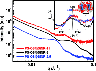
ATR-FTIR spectra of the PS-OS@SiNR samples showed absorption bands between 1130 and 1000 cm−1, suggesting a retained Si–O–Si structure similar to that observed for SiNRs and OS@SiNR (ESI Fig. S1a–c† black ATR-FTIR spectra). However, the PS-OS@SiNR samples showed additional peaks for ether (1098 cm−1), phenyl (1641 cm−1), sulfonate (1296 cm−1), and aliphatic (2875 cm−1) groups which corresponded to the coverage of the hollow OS-SiNR by the PEG based polymer-surfactant. In order to ascertain the morphology of the nanorods in PS-OS@SiNR and for understanding whether the hollow core of the rods was retained after coupling with organosilane and subsequently with the polymer surfactant, we performed cryo-TEM studies on the composite samples. Cryo-TEM of PS-OS@SiNR 2.5, 8 and 11 samples showed a retained rod like structure with a hollow core (Fig. 5a–c). It was interesting to note that the SAXs studies at 25 °C of the three PS-OS@SiNR samples, viz. 2.5, 8, and 11 (Fig. 6), showed apparent structure factor Sapp(q) peaks centred at q ≈ 0.015, 0.016 and 0.018 Å−1, respectively. These peaks corresponded to average d spacing values (for different aspect ratios) of 40 (2.5), 38.5 (8), and 35 (11) nm, and could be attributed to the centre-to-centre distance between the polymer-surfactant chain conjugated hollow silica nanorods (inset) assembled in a side-to-side fashion in the PS-OS@SiNR composite samples (inset in Fig. 6). The control SAXs profile of the polymer surfactant at 25 °C showed a dPS-spacing of 4.8 nm (q ≈ 0.13 Å−1; ESI Fig. S6†), suggesting that the d spacing (≈35–40 nm) for side-to-side ordering in PS-OS@SiNR samples was in fact correlated to the centre-to-centre distance between polymer surfactant molecules (4.8 nm) plus twice the silica shell radius of the nanorods (2 × ≈20 nm).
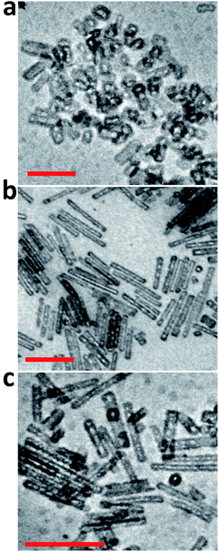 | ||
| Fig. 5 Cryo-transmission electron micrographs of PS-OS@SiNR liquid samples with different aspect ratios: (a) 2.5, (b) 8, and (c) 11. The scale bar indicates 200 nm. | ||
Further to address the porosity, we performed N2 gas adsorption experiments at −196 °C (77 K) on the OS@SiNR samples, and compared the results with those of their unmodified counterpart, SiNRs. The organosilane coupling on the surface of SiNRs reduced the BET surface area to 81 m2 g−1 (from 127 m2 g−1), 86 m2 g−1 (from 143 m2 g−1) and 70 m2 g−1 (from 196 m2 g−1) for OS@SiNR-2.5, OS@SiNR-8 and OS@SiNR-11, respectively (for details see ESI Fig. S7b and e†). The shape of N2 adsorption curves of OS@SiNR showed type 4 behaviour (similar to SiNR adsorption isotherms; ESI Fig. S7a and d†), and the results were in good agreement with the TEM data which showed retained porosity even after the chemical modification with organosilane. Although mesoporous solids have been well studied for their gas uptake and separation measurements,3–11 gas adsorption in mesoporous liquids with anisotropic pores has rarely been performed.33 Therefore moving ahead with this idea, we performed N2 gas adsorption studies on the solvent-free PS-OS@SiNR composite liquids by using the procedure shown in ESI Fig. S8†. The N2 adsorption isotherms of all the PS-OS@SiNR samples at −196 °C showed the characteristic adsorption of a non-porous/macroporous sample with weak adsorbate–adsorbent interactions (ESI Fig. S7c and f†). The BET surface areas of the samples were found to be 12.1, 27, and 5.1 m2 g−1 for PS-OS@SiNR-2.5, PS-OS@SiNR-8, and PS-OS@SiNR-11, respectively. These results were in contradiction to the study on similar porous liquids but based on hollow silica nanospheres, whereby a significant N2 adsorption was shown at −196 °C.19 In order to understand this further, a control BET experiment performed on a neat polymer surfactant provided a similar adsorption isotherm related to a non-porous material (ESI Fig. S9a and b†). It was surprising that although the cryo-TEM of PS-OS@SiNR samples showed hollow cores, the N2 gas adsorption isotherm showed a steep decrease in the BET surface area from OS@SiNR to PS-OS@SiNR. This suggested blockage of the small micropores in the silica shell. In order to understand this, we revisited the DSC data of PS-OS@SiNR samples which showed a Tc in the range of ca. −6 °C to −10 °C, and a glass transition temperature (Tg) in the range of −60 to −70 °C which was associated with the polymer surfactant (ESI Fig. S3†). It is important to note here that the N2 adsorption experiments were carried out at −196 °C, much lower than the Tg of the PS-OS@SiNR system. We hypothesize that the decrease in surface area from OS@SiNR to PS-OS@SiNR was associated with the polymer surfactant forming a glassy layer around the silica nanorods which ultimately prevented N2 sequestration and adsorption in the hollow cores. To validate our hypothesis, we carried out control N2 adsorption experiments with a well-known sorbent, activated charcoal, in the presence and absence of PS (ESI Fig. S10†). The BET results showed that the surface area of neat activated charcoal (1046 m2 g−1) (ESI Fig. S10a and c†) was highly reduced in the presence of the polymer surfactant (3.89 m2 g−1) (ESI Fig. S10b and d†).
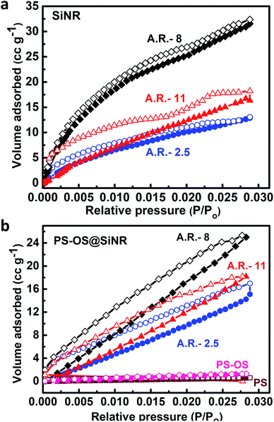
In order to alleviate the problem related to the non-adsorption of N2 gas at −196 °C in the PS-OS@SiNR composite, we performed CO2 physi-sorption measurements at 0 °C i.e. above the Tg and Tc of the PS-OS@SiNR samples. Generally, CO2 physi-sorption experiments are performed at 0 °C, with the saturation pressure (Po) of CO2 being approximately 34.7 bar at this temperature.34 However due to instrument limitation, CO2 adsorption measurements were carried out in a sub-atmospheric (low) pressure sorption analyser at 0 °C, providing a maximum relative pressure (P/Po) of ca. 0.03, much similar to the studies reported in the literature.34 The CO2 adsorption isotherms for PS-OS@SiNR with aspect ratios 2.5, 8 and 11 showed an uptake of approximately 17 cm3 g−1, 25 cm3 g−1, and 18 cm3 g−1, respectively, at 0.03 P/Po (Fig. 7b). This corresponded to 3.3% w/w, 4.8% w/w and 3.4% w/w CO2 adsorption for PS-OS@SiNR samples with aspect ratios 2.5, 8 and 11, respectively. This indicated that the amount of CO2 adsorbed did not exhibit significant dependence on the aspect ratio of the nanorods. Moreover, these values were found to be roughly similar to the literature obtained values for solid mesoporous silica (MCM-48) samples which showed ≈34 cm3 g−1 of CO2 physi-sorption, at similar temperature and pressure.34 It was also observed that the adsorption and desorption isotherms of all the samples exhibited significant hysteresis. This could be associated with the diffusion controlled process,35 whereby an adsorption equilibrium could not be attained probably due to the complex porous structure of the silica shell combined with high viscosity of the solvent-free composite liquid. In comparison, experiments performed with bare SiNRs having aspect ratios 2.5, 8, and 11 showed a CO2 adsorption of 13 cm3 g−1, 32.4 cm3 g−1, and 18.2 cm3 g−1, respectively (Fig. 7a), suggesting that the hollow cavity within the SiNRs and PS-OS@SiNR was available for CO2 gas adsorption at 0 °C and at 0.03 P/Po relative pressure. Control experiments with the PS-OS or PS alone showed minimal CO2 adsorption of 0.7 cm3 g−1 and 0.6 cm3 g−1, respectively, as shown in Fig. 7b. Thus, the adsorption experiments combined with the cryo-TEM images in Fig. 5c suggested that the mesopores were not blocked by the sequential modification steps of bare SiNRs, and were accessible for CO2 adsorption at 0 °C in the PS-OS@SiNR liquid samples.
4. Conclusion
We show here the design and development of another class of composite and solvent-free porous liquids based on anisotropic “hollow-core and silica-shell” nanorods with varying aspect ratios and surface engineered with organosilane followed by electrostatic and stoichiometric coupling of oppositely charged polymer surfactant molecules. The TEM and SAXs studies on bare and unmodified silica nanorods indicate retention of hollow cores, while N2 adsorption experiments provide a surface area from ≈120 to ≈200 m2 g−1. The solvent-free composite material comprises ≈3 v/v% pores, and exhibits liquid-like flow behaviour above the melting transition temperature of 15–20 °C. We further show that whilst N2 adsorption in the composite liquid at −196 °C is inhibited due to the glassy polymer surfactant layer, CO2 adsorption at 0 °C is still accomplishable. The CO2 adsorption experiment on the solvent-free porous liquid indicates an uptake of up to ≈4.8 w/w%, which is comparable to that of solid mesoporous silica. Our results therefore indicate the formation of a model porous material which not only sequesters gas molecules but also has the ability to flow like a liquid and thus could be retrofitted in flow pipes or employed for various applications such as gas separation, catalysis, etc. This would allow various possibilities and design opportunities that can be created to utilize high fraction free volume liquid-like materials in flow processes to allow increased kinetics of exchange of trapped gaseous species. Further, the presence of rods can provide interesting rheological properties and thus show a unique structure–property relationship. In conclusion, through this study we envisage a path forward for creating multifunctional materials which can sequester harmful gases, and catalytically convert them into non-hazardous substances.Conflicts of interest
There are no conflicts to declare.Acknowledgements
K·P. S. thanks the SERB-DST and IRCC, IIT Bombay, for funding through grant numbers EMR/2016/000174 and 15IRCCSG029, respectively. P. D. and R. K. thank the Department of Chemistry, IITB, for Institute Post-Doctoral funding, and T. A. funding, respectively. K. P. S. thanks the SAIF, IIT Bombay, for SAXs facility obtained through DST grant number C/3217/IFD/2017-18.References
- F. Gándara, H. Furukawa, S. Lee and O. M. Yaghi, J. Am. Chem. Soc., 2014, 136, 5271–5274 CrossRef PubMed.
- Y.-B. Huang, J. Liang, X.-S. Wang and R. Cao, Chem. Soc. Rev., 2017, 46, 126–157 RSC.
- B. Li, H.-M. Wen, W. Zhou and B. Chen, J. Phys. Chem. Lett., 2014, 5, 3468–3479 CrossRef CAS PubMed.
- J. A. Mason, M. Veenstra and J. R. Long, Chem. Sci., 2014, 5, 32–51 RSC.
- P. J. Waller, F. Gándara and O. M. Yaghi, Acc. Chem. Res., 2015, 48, 3053–3063 CrossRef CAS PubMed.
- D. Banerjee, C. M. Simon, A. M. Plonka, R. K. Motkuri, J. Liu, X. Chen, B. Smit, J. B. Parise, M. Haranczyk and P. K. Thallapally, Nat. Commun., 2016, 7, 11831 CrossRef PubMed.
- X. Yang and Q. Xu, Cryst. Growth Des., 2017, 17, 1450–1455 CrossRef CAS.
- S. B. Alahakoon, C. M. Thompson, G. Occhialini and R. A. Smaldone, ChemSusChem, 2017, 10, 2116–2129 CrossRef CAS PubMed.
- D. Banerjee, S. K. Elsaidi and P. K. Thallapally, J. Mater. Chem. A, 2017, 5, 16611–16615 RSC.
- K. Dey, M. Pal, K. C. Rout, S. Kunjattu H, A. Das, R. Mukherjee, U. K. Kharul and R. Banerjee, J. Am. Chem. Soc., 2017, 139, 13083–13091 CrossRef CAS PubMed.
- C. H. Hendon, A. J. Rieth, M. D. Korzyński and M. Dincă, ACS Cent. Sci., 2017, 3, 554–563 CrossRef CAS PubMed.
- H. Furukawa, K. E. Cordova, M. O'Keeffe and O. M. Yaghi, Science, 2013, 341, 1230444 CrossRef PubMed.
- A. Corma, Chem. Rev., 1997, 97, 2373–2420 CrossRef CAS PubMed.
- T. Hasell and A. I. Cooper, Nat. Rev. Mater., 2016, 1, 16053 CrossRef CAS.
- N. Giri, M. G. Del Pópolo, G. Melaugh, R. L. Greenaway, K. Rätzke, T. Koschine, L. Pison, M. F. C. Gomes, A. I. Cooper and S. L. James, Nature, 2015, 527, 216 CrossRef CAS PubMed.
- G. Melaugh, N. Giri, C. E. Davidson, S. L. James and M. G. Del Pópolo, Phys. Chem. Chem. Phys., 2014, 16, 9422–9431 RSC.
- N. O'Reilly, N. Giri and S. L. James, Chem.–Eur. J., 2007, 13, 3020–3025 CrossRef PubMed.
- T. Shi, Y. Zheng, T. Wang, P. Li, Y. Wang and D. Yao, ChemPhysChem, 2018, 19, 130–137 CrossRef CAS PubMed.
- J. Zhang, S. H. Chai, Z. A. Qiao, S. M. Mahurin, J. Chen, Y. Fang, S. Wan, K. Nelson, P. Zhang and S. Dai, Angew. Chem., Int. Ed., 2015, 54, 932–936 CrossRef CAS PubMed.
- R. Gaillac, P. Pullumbi, K. A. Beyer, K. W. Chapman, D. A. Keen, T. D. Bennett and F.-X. Coudert, Nat. Mater., 2017, 16, 1149 CrossRef CAS PubMed.
- Y. Min, M. Akbulut, K. Kristiansen, Y. Golan and J. Israelachvili, Nat. Mater., 2008, 7, 527–538 CrossRef CAS PubMed.
- M. Hagen, E. Meijer, G. Mooij and D. Frenkel, Nature, 1993, 365, 425–426 CrossRef CAS.
- A. B. Bourlinos, R. Herrera, N. Chalkias, D. D. Jiang, Q. Zhang, L. A. Archer and E. P. Giannelis, Adv. Mater., 2005, 17, 234–237 CrossRef CAS.
- S. C. Warren, M. J. Banholzer, L. S. Slaughter, E. P. Giannelis, F. J. DiSalvo and U. B. Wiesner, J. Am. Chem. Soc., 2006, 128, 12074–12075 CrossRef CAS PubMed.
- R. Rodriguez, R. Herrera, L. A. Archer and E. P. Giannelis, Adv. Mater., 2008, 20, 4353–4358 CrossRef CAS.
- A. B. Bourlinos, S. Ray Chowdhury, R. Herrera, D. D. Jiang, Q. Zhang, L. A. Archer and E. P. Giannelis, Adv. Funct. Mater., 2005, 15, 1285–1290 CrossRef CAS.
- M. L. Jespersen, P. A. Mirau, E. v. Meerwall, R. A. Vaia, R. Rodriguez and E. P. Giannelis, ACS Nano, 2010, 4, 3735–3742 CrossRef CAS PubMed.
- A. B. Bourlinos, A. Stassinopoulos, D. Anglos, R. Herrera, S. H. Anastasiadis, D. Petridis and E. P. Giannelis, Small, 2006, 2, 513–516 CrossRef CAS PubMed.
- L. Sun, J. Fang, J. C. Reed, L. Estevez, A. C. Bartnik, B. R. Hyun, F. W. Wise, G. G. Malliaras and E. P. Giannelis, Small, 2010, 6, 638–641 CrossRef CAS PubMed.
- T. Schilling, M. A. Miller and P. van der Schoot, EPL, 2015, 111, 56004 CrossRef.
- C. Gao, Z. Lu and Y. Yin, Langmuir, 2011, 27, 12201–12208 CrossRef CAS PubMed.
- P. Shinde, S. S. Gupta, B. Singh, V. Polshettiwar and B. L. Prasad, J. Mater. Chem. A, 2017, 5, 14914–14921 RSC.
- P. Li, R. Yang, Y. Zheng, P. Qu and L. Chen, Carbon, 2015, 95, 408–418 CrossRef CAS.
- Z. Bacsik, N. Ahlsten, A. Ziadi, G. Zhao, A. E. Garcia-Bennett, B. Martín-Matute and N. Hedin, Langmuir, 2011, 27, 11118–11128 CrossRef CAS PubMed.
- P. I. Ravikovitch and A. V. Neimark, Adsorption, 2005, 11, 265–270 CrossRef.
Footnotes |
| † Electronic supplementary information (ESI) available. See DOI: 10.1039/c9na00353c |
| ‡ These authors contributed equally. |
| This journal is © The Royal Society of Chemistry 2019 |


