
 Open Access Article
 This Open Access Article is licensed under a Creative Commons Attribution-Non Commercial 3.0 Unported Licence
Three-step-in-one synthesis of supercapacitor MWCNT superparamagnetic magnetite composite material under flow†
Thaar M. D.
Alharbi
ab,
Ahmed H. M.
Al-Antaki
 a,
Mahmoud
Moussa
c,
Wayne D.
Hutchison
d and
Colin L.
Raston
*a
a,
Mahmoud
Moussa
c,
Wayne D.
Hutchison
d and
Colin L.
Raston
*a
aFlinders Institute for Nanoscale Science and Technology, College of Science and Engineering, Flinders University, Adelaide, SA 5001, Australia. E-mail: colin.raston@flinders.edu.au
bPhysics Department, Faculty of Science, Taibah University, Almadinah Almunawarah, Saudi Arabia
cSchool of Chemical Engineering and Advanced Materials, The University of Adelaide, Adelaide, SA 5001, Australia
dSchool of Science, University of New South Wales, ADFA campus, Canberra BC, Australian Capital Territory 2610, Australia
First published on 19th August 2019
Abstract
Composites of multi-walled carbon nanotubes (MWCNTs) and superparamagnetic magnetite nanoparticles, Fe3O4@MWCNT, were synthesized in DMF in a vortex fluidic device (VFD). This involved in situ generation of the iron oxide nanoparticles by laser ablation of bulk iron metal at 1064 nm using a pulsed laser, over the dynamic thin film in the microfluidic platform. The overall processing is a three-step in one operation: (i) slicing MWCNTs, (ii) generating the superparamagnetic nanoparticles and (iii) decorating them on the surface of the MWCNTs. The Fe3O4@MWCNT composites were characterized by transmission electron microscopy, scanning transmission electron microscope, TG analysis, X-ray diffraction and X-ray photoelectron spectroscopy. They were used as an active electrode for supercapacitor measurements, establishing high gravimetric and areal capacitances of 834 F g−1 and 1317.7 mF cm−2 at a scan rate of 10 mV s−1, respectively, which are higher values than those reported using similar materials. In addition, the designer material has a significantly higher specific energy of 115.84 W h kg−1 at a specific power of 2085 W kg−1, thereby showing promise for the material in next-generation energy storage devices.
1. Introduction
In recent years the drive for safe, efficient and high-performance energy storage devices, has resulted in major research efforts in supercapacitors. This has been driven by their potential for high power density, outstanding safety, fast charge/discharge rates, excellent reliability, and long cycling life.1–3 Several nanostructured materials have shown to be effective as electrodes for supercapacitors. These include carbon nanotubes,1,4 graphene,5,6 a number of other types of structured nanoparticles,7,8 nanowires,9,10 porous nanoflakes,11,12 and nanospheres.13,14 Composites of metal oxides and carbon based materials, especially carbon nanotubes, have been used as electrode materials, establishing that the electrochemical performance is enhanced.15,16Decorating carbon nanotubes with inorganic nanoparticles has received considerable attention both in fundamental research and the industrial arena.17 This relates to the unique physical and chemical properties of the composite materials. Indeed, MWCNTs decorated with iron oxide particles in general are promising composite materials for a variety of applications such as hydrogen storage,18 imaging and therapy,17,19 gas sensors,20 catalysis,17,21 CNT-based magnetic materials,22 CNT field emitters,17,23 and CNT-based electronic devices.17,24,25 Various routes have been developed in gaining access to such material, including solvothermal,26 hydrothermal,27 microwave,28 laser ablation29 and ultra-sonication processing,30 high-temperature decomposition,31 laser pyrolysis32 and chemical vapour deposition.33 Freedman et al.34 and Singhal et al.35 have demonstrated that a magnetic carbon nanotube pipette is effective for transferring liquid into and within a single cell. In addition, Šljukić et al.36 have shown that the electrochemical activity of carbon nanotubes for the reduction of H2O2 can arise from iron oxide nanoparticles decorated on CNT. Also noteworthy is that carbon nanotubes decorated with iron(III) oxide (Fe2O3) nanoparticle embedded in a co-polymer (derived from pyrrole and 3-carboxylated pyrrole) are highly sensitive for detecting H2S, as reported by Kim et al.37 Thus CNT–iron oxide nanoparticle composites have a diverse range of applications, and accordingly we sort to develop a robust synthesis of such material, ideally under continuous flow, as a potentially scalable process.
Previously we reported on the synthesis of superparamagnetic magnetite (Fe3O4) nanoparticles, spheroidal and hexagonal shaped, with an average size of ca. 15 nm, using a vortex fluidic device (VFD).38 Here the magnetite nanoparticles are generated by pulsed laser ablation of an iron rod (high purity, >99.998%) at 1064 nm, with the rod positioned over the dynamic thin film in the VFD, Fig. 1a, under at atmosphere of air. This is a single-step continuous flow process, and the operation of the VFD is effectively using it as a metal vapour synthesiser. In an analogous way, the VFD has been used for decorating hexagonal boron nitride (h-BN) with similar sized magnetite nano-particles, now as a one step process for making composite materials.39 Inspired by the aforementioned findings, we were motivated to translate this knowhow into developing a facile continuous flow VFD mediated process for decorating MWCNTs with magnetite nanoparticles, Fe3O4@MWCNT, in using the shear stress in the VFD to disentangle the MWCNTs which while irradiated with a the pulsed laser are sliced into more processible lengths.40 Thus it is a novel three in one continuous flow process, and we establish that the resulting composite material, Fe3O4@MWCNTs, is an active electrode for supercapacitance, achieving a high gravimetric (834 F g−1) and areal (1317.7 mF cm−2) capacitances, which are enhanced compared with those previously reported for iron oxide/carbon anodes.41 We note that the decoration of SWCNTs with magnetite nanoparticles has been established using the related spinning disc processor (SDP), also under continuous flow, but the process requires the use of harsh chemicals and pre-treatment (oxidation and binding of Fe2+ and Fe3+) of the SWCNTs,42 and thus where the integrity of the carbon nanotubes is lost.
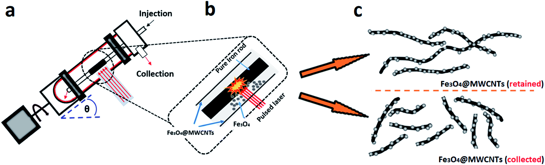 | ||
| Fig. 1 Schematic illustration of the experimental procedure for the preparation for Fe3O4@MWCNT. (a) The vortex fluidic device (VFD) and laser Nd:YAG processing at 1064 nm. (b) Zoomed in schematic for generating Fe3O4 NPs under laser irradiation of an iron rod (power at 250 mJ). (c) Fe3O4@MWCNT exiting the tube under continuous flow (collected) and retained in the tube. | ||
The VFD is a versatile microfluidic platform with a diversity of applications, including in processing carbon nanomaterials, as in slicing of SWCNTs, especially in controlling their length,43 exfoliation of graphite and boron nitride,44 transforming graphene oxide sheets into scrolls,45 decorating carbon nano-onions with Pt46 and Pd47 nanoparticles, the synthesis of carbon dots,48 and the fabrication of C60 tubules using water as an ‘anti-solvent’.49 Other applications of the VFD include controlling chemical reactivity and selectivity,50 protein folding,51 enhancing enzymatic reactions52 and protein immobilization.53 The dynamic thin film in a VFD has Stewartson/Ekman layers and Faraday pressure waves, with the liquid moving up the rapidly rotating tube under gravitational force and exiting at the top.54 The continuous flow mode of operation of the VFD has the attractive feature of addressing scalability of a process at the inception of the research. Here jet feeds deliver reagents into an inclined rapidly rotating tube, typically a 20 mm O.D. glass or quartz tube.55
2. Experimental section
2.1. Materials
MWCNTs used in the present work have an average outside diameter (O.D.) × inside diameter (I.D.) × length equivalent dimensions 10 nm ± 1 nm × 4.5 nm ± 0.5 nm, and 3 to 6 μm respectively. They were purchased from Sigma-Aldrich, as chemical vapour deposition prepared material with an as received purity ≥ 98%, and were used as received. N,N-Dimethylformamide (DMF) was purchased from Sigma-Aldrich and used as received. High purity Fe (>99.998%) 8361 h iron rod, 5 mm in diameter (Koch-Light Laboratories) was used as the laser target and source of metal.2.2. Fabrication of Fe3O4@MWCNT
The preparation of Fe3O4@MWCNT nanocomposites is shown in Fig. 1a. MWCNTs were dispersed in N,N-dimethylformamide (DMF) at a concentration of 0.08 mg mL−1 and the mixture ultrasonicated for 15 minutes prior to VFD processing. The experimental setup mainly followed the previously published work for the VFD mediated slicing of CNTs and the synthesis of superparamagnetic nanoparticles,38,40,43 in merging two different applications of the VFD. The experiments were carried out using the continuous flow mode of operation of the device at a flow rate of 0.45 mL min−1. Stainless steel jet feed was used to deliver MWCNTs dispersed in DMF solution to the bottom of the rapidly rotating quartz tube (O.D. 20 mm, I.D. 17.5 mm). The tilt angle (θ) of the device was 45°, which is the optimal angle for a number of VFD processes,43–45,48 relative to the horizontal position. For fabricating Fe3O4@MWCNTs, the iron rod was immobilized on a stainless steel jet feed and irradiated in the VFD tube at a wavelength of 1064 nm using a Q-switched Nd:YAG laser (Spectra Physics GCR170) operating at a pulse repetition rate of 10 Hz. The power of the laser was optimized first by conducting the experiment under continuous flow conditions at different laser powers, 250 mJ, 400 mJ and 600 mJ, as shown in Fig. S5 (ESI†). For high laser powers, 400 and 600 mJ, the MWCNTs were unzipped and fragmented, whereas at the optimum laser power (250 mJ), Fe3O4 nanoparticles were generated and decorated on the surface of MWCNTs. Initially the MWCNTs were dispersed in DMF at a concentration of 0.08 mg mL−1 and were injected into the base of the quartz tube through a jet feed using a 50 mL glass syringe, at a flow rate of 0.45 mL min−1 while the iron rod was irradiated with the pulsed laser. After the 50 mL of the solutions was delivered, the experiment was stopped, affording two products, one exiting the VFD tube during the processing (collected), which accounted for 42% of the isolated material, with 58% of the material generated remaining in the tube (retained). Both products contained MWCNTs decorated with Fe3O4 nanoparticles in a high yield, based on the amount of MWCNTs consumed and the overall weight of the combined product taking into account the ratio of magnetite to MWCNTs.2.3. Electrochemistry
A specific amount of active material (10 mg) was sonicated for 1 h in 20 mL of ethanol. Next, the resulting suspension was vacuum filtered through a PTFE membrane to make a free-standing film. The composite film was cut into electrodes of footprint area of 1 cm2, and platinum foils were used as current collectors and 1 M Na2SO4 as electrolyte. Cyclic voltammetry (CV) and galvanostatic charge/discharge (CD) were carried out by a two-electrode configuration using a CHI 660E electrochemical workstation. All measurements were performed at room temperature. The gravimetric capacitance and areal capacitance were calculated from CV curves.2.4. Characterization
X-ray powder diffraction (XRD) data were collected using a Bruker Advanced D8 diffractometer (capillary stage) using Co-Kα (λ = 1.7889 Å, 35 kW/28 mA, 2θ = 10–90°). Thermogravimetric analysis (TGA) was recorded on a Perkin Elmer STA8000 operating at a heating rate of 10 °C min−1 under an air gas flow. Atomic force microscopy (AFM) using a Nanoscope 8.10 in tapping mode and transmission electron microscopy (TEM) was conducted on a TECNAI 20 microscope operated at 120 and 200 kV. STEM investigation and compositional mapping were conducted using an aberration-corrected FEI Titan Themis TEM operating at 200 kV equipped with an energy dispersive X-ray spectroscopy (EDX) detector. Magnetization measurements used a Quantum Design PPMS with ACMS option at room temperature (295 K) in applied magnetic fields up to 2.50 T.3. Results and discussion
3.1. Fabrication of Fe3O4@MWCNT
We have developed a high yielding method for preparing a composite material based on MWCNTs decorated with superparamagnetic magnetite (Fe3O4) nanoparticles, Fe3O4@MWCNT, as a three in one process – slicing, laser ablation and growth of nanoparticles, and decoration. The solvent of choice was DMF, with the processing devoid of other reagents, and the processing is therefore limiting the generation of a waste stream for any downstream applications. Salient features for preparing Fe3O4@MWCNT are schematically illustrated in Fig. 1. The Fe3O4 nanoparticles (NPs) are generated in situ in the VFD by irradiating a high purity (>99.998%) iron rod (5 mm diameter) with a pulsed laser (Q-switched Nd:YAG) operating at 1064 nm wavelength, Fig. 1b. MWCNTs dispersed in DMF were delivered to the bottom of the rapidly rotating quartz VFD tube through a jet feed with an iron rod attached. As the liquid passes through the laser beam the MWCNTs are sliced into shorter tubes and simultaneously decorated with Fe3O4 NPs, Fig. 1c. The length distribution of Fe3O4@MWCNT exiting the tube is centred at 500 nm (inset Fig. 3a). MWCNTs which were retained in the VFD during the processing were similarly decorated with Fe3O4 NPs, Fig. 1c, but they are significantly longer at ca. 2 μm. The reason for the longer lengths of MWCNTs in the composite material being retained in the tube presumably relates to the build-up, on both sides of the laser beam, of magnetite being faster than untangling and slicing of the MWCNTs. Such build up is likely to result in magnetite particles bridging different tube which are then locked into place, with the shear stress in the fluid dynamics unable to separate them. MWCNTs sliced prior to a substantial build-up of magnetite particles on their surface, can then be decorated and move under the fluid flow. See below for further discussion on the size of the magnetite NPs and associated mass differences, and potential effect on the processing.3.2. Characterisation
The nature of the Fe3O4@MWCNT nanocomposite was investigated using AFM, TEM, HRTEM and STEM. Fig. 2a and d show AFM and low magnification TEM images for the material retained in the tube during processing revealing bundles of strands mixed with a high density of Fe3O4 nanoparticles, seen as black areas. These modified MWCNTs appear unaltered in length relative to the as received material. Fig. 2b and c show TEM and HRTEM images of the same material, revealing MWCNTs decorated with Fe3O4 NPs. Corresponding images for Fe3O4@MWCNT flowing out of the tube (collected) are shown in Fig. 3a and d, clearly establishing that the MWCNTs have been sliced down to 500 nm in length (inset Fig. 3a) as well as being decorated with Fe3O4 nanoparticles. Fig. 3b and c show TEM and HRTEM images of the collected Fe3O4@MWCNT, which are also decorated with Fe3O4 NPs. We note that Fe3O4@MWCNTs (retained) has MWCNTs decorated with Fe3O4 nanoparticles with an average diameter of 15.1 ± 2.4 nm, as determined using HRTEM, Fig. 2c, whereas they are smaller in diameter, 10 ± 1.2 nm, for the material exiting the VFD tube under flow, Fig. 3c.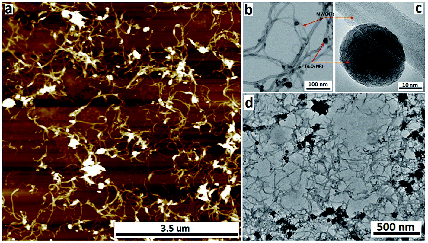 | ||
| Fig. 2 (a) AFM image, (b) STEM image, (c) HRTEM image and (d) TEM of Fe3O4@MWCNT (retained), formed in the VFD (optimised parameters) operating at 8.5k rpm rotational speed, under continuous flow, with the concentration of the as received MWCNTs at 0.08 mg mL−1 (DMF), tilt angle 45°, flow rate 0.45 mL min−1, and laser power 250 mJ, with the MWCNTs ca. 2 μm in length. | ||
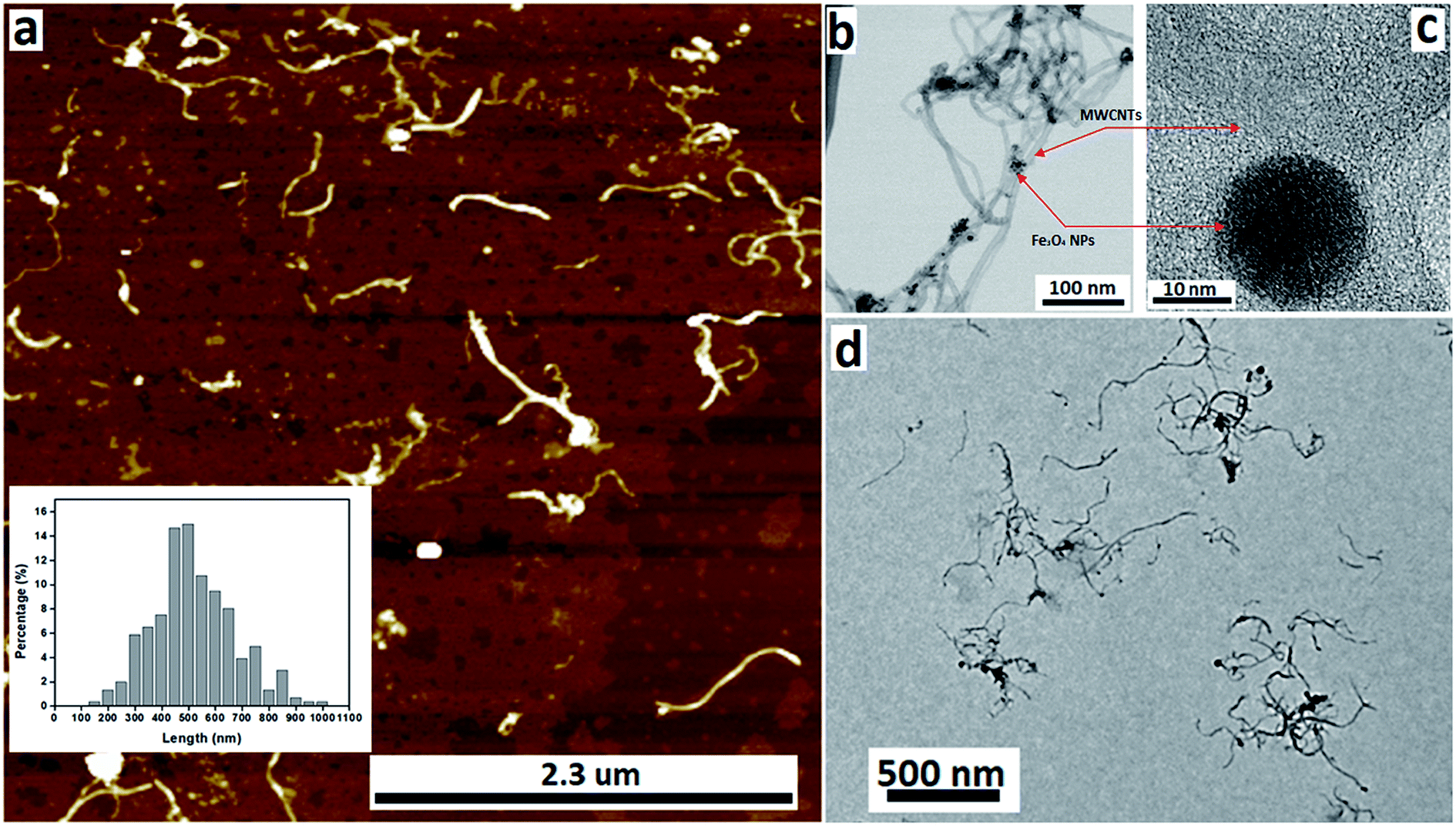 | ||
| Fig. 3 (a) AFM image, (b) STEM image, (c) HRTEM image and (d) TEM image of Fe3O4@MWCNT exiting the tube under continuous flow (collected), processed in the VFD (optimised parameters) operating at 8.5k rpm rotational speed, with the concentration of the as received MWCNTs at 0.08 mg mL−1 (DMF), tilt angle 45°, flow rate 0.45 mL min−1, and laser power 250 mJ. The inset in (a) is the length distribution of the carbon nanotubes in Fe3O4@MWCNTs (collected). | ||
High-resolution STEM was used to gain further insight into the nature of the Fe3O4@MWCNT nanocomposite. Fig. 4a displays BF and HAADF-STEM images of collected Fe3O4@MWCNT along with the elemental mapping. Interestingly, while most Fe3O4 NPs decorate the surface of the MWCNTs, Fig. 3a and b, there are some that are encapsulated inside the MWCNTs, Fig. 4a, as highlighted by elemental mapping of Fe and O. BF and HAADF-STEM images, and the corresponding elemental mapping, for the collected material are shown in Fig. 4b, with the mapping consistent with coating of MWCNTs with Fe3O4 NPs. BF and HAADF, and STEM images, Fig. 4a and b also establish that the size of Fe3O4 nanoparticles for the collected material are smaller than those of the retained material. In addition, VFD processing in the absence of MWCNTs, generated Fe3O4 nanoparticles which were also smaller for the collected material, average diameter ca. 10 nm, compared to the material retained in the VFD, average diameter ca. 15, as determined using AFM (ESI Fig. S8†). This is in good agreement with HRTEM results for the NPs formed in the presence of MWCNTs, Fig. 2c and 3c. The results suggest that the larger particles, which have higher mass, determine whether the MWCNTs are decorated and sliced and free to leave the tube, or decorated without slicing and retained in the tube, i.e. if the build-up of NPs on the surface of MWCNTs is too fast relative to slicing the MWCNTs, then they will be retained in the quartz tube in the VFD. Additional STEM images are provided in the ESI, Fig. S3 and S4.†
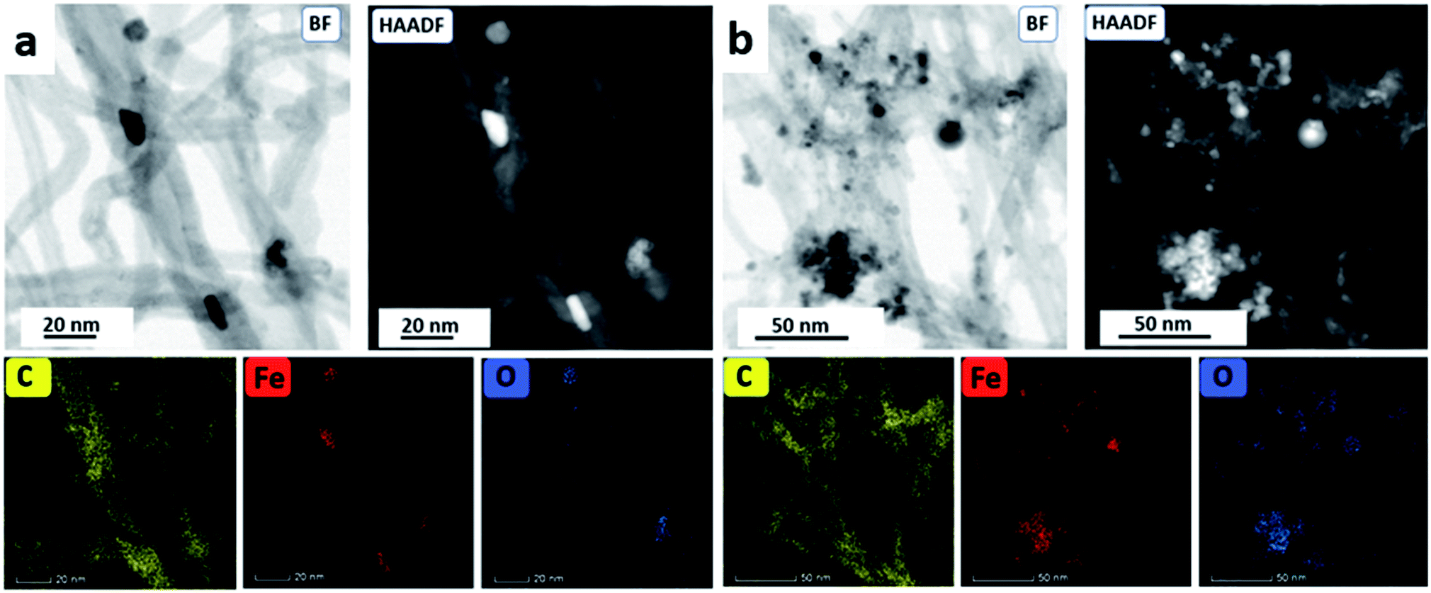 | ||
| Fig. 4 (a) BF and HAADF-STEM images of Fe3O4@MWCNT (collected) with the corresponding STEM element mapping. (b) BF and HAADF-STEM image of Fe3O4@MWCNT (retained) with the corresponding STEM element mapping. | ||
The X-ray diffraction (XRD) patterns of MWCNTs before processing (as received), Fe3O4@MWCNT (collected and retained) samples are shown in Fig. 5a. MWCNTs (as received) have diffraction peaks at 29.7° and 51.2°, which are assigned to the (002) and (110) planes of MWCNTs (ESI Fig. S6†),15,27 whereas for Fe3O4 nanoparticles only, there are seven characteristic peaks (21.5°, 37.3°, 44.6°, 54.9°, 62°, 69.1°, and 74.1°) which correspond to the (111), (220), (311), (400), (422), (511), and (440) reflections of magnetite (Fe3O4) (ESI Fig. S6†).26,27,31,38 XRD pattern for the nanocomposite material is shown in Fig. 5a, establishing the formation of magnetic NPs, with all of the peaks corresponding to magnetite and MWCNTs, consistent with the formation of Fe3O4@MWCNT.
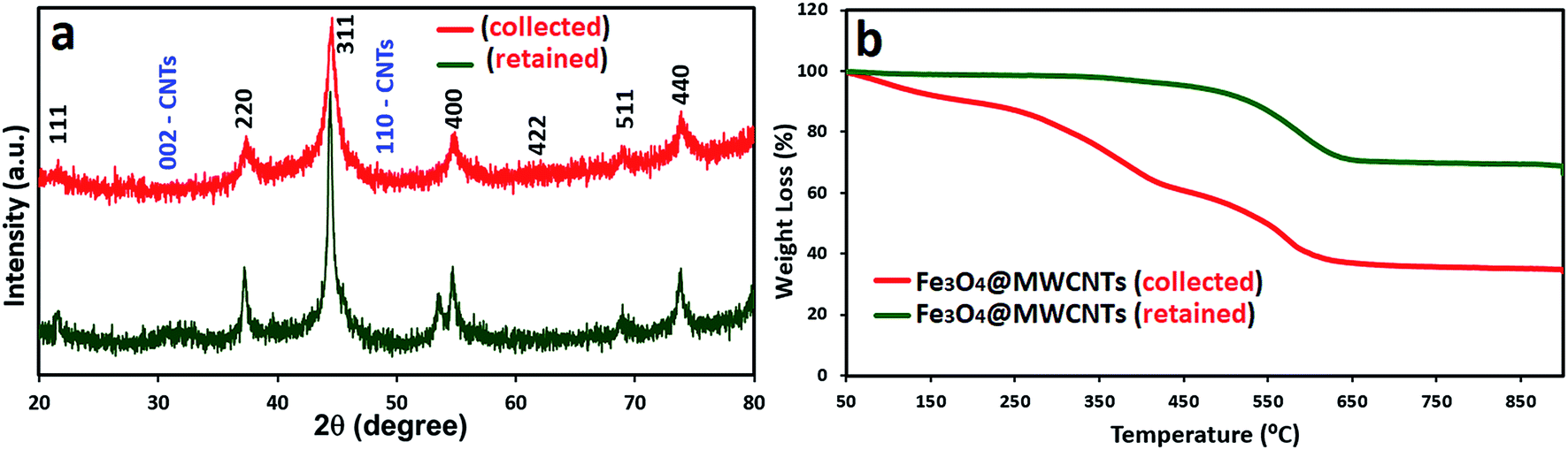 | ||
| Fig. 5 (a) XRD patterns and (b) TGA curves for Fe3O4@MWCNT exiting (red) and retained (green) in the quartz tube, processed in the VFD (optimised parameters) operating at 8.5k rpm rotational speed, with the concentration of the as received MWCNTs at 0.08 mg mL−1 (DMF), tilt angle 45°, flow rate 0.45 mL min−1, and laser power 250 mJ. | ||
Thermogravimetric analysis (TGA) was carried out under air, for MWCNTs (as received), (ESI Fig. S7†), and both Fe3O4@MWCNT nanocomposite materials (retained and collected), Fig. 5b. For as-received MWCNTs the material is stable when the temperature is <550 °C, with then a significant weight loss >600 °C corresponding to the decomposition of MWCNTs.56 The weight loss of retained Fe3O4@MWCNT nanocomposite was about 29.6 wt% between temperature 350–650 °C, whereas, the collected nanocomposite shows greater weight loss for increasing temperatures. Here there are two regions of weight loss, 40 and 25 wt% between 50–400 °C and 400–650 °C, respectively. The differences in the weight loss between two nanocomposite material (retained and collected) is ascribed to the uptake of DMF in solution when the MWCNTs are sliced. If the material retained in the VFD quartz tube is unsliced or has very little slicing, the end caps of the MWCNTs will limit the amount of solvent that can be taken up inside the nanotubes.57,58 Specific surface area from BET for MWCNTs (as received), Fe3O4@MWCNT (collected) and Fe3O4@MWCNT (retained) are 127.0396 m2 g−1, 83.8937 m2 g−1 and 55.1279 m2 g−1, respectively, Fig. S9.† The lower surface area for Fe3O4@MWCNT (collected) and Fe3O4@MWCNT (retained) compared to as received MWCNTs presumably relates to the build up of magnetite material, lowering the relative surface area. The higher surface area for the material exiting the tube relates to the now availability of the internal surface of the sliced MWCNTs.59
X-ray photoelectron spectroscopy (XPS) was used to investigate the elemental composition and chemical state of Fe3O4@MWCNT, with the results shown in Fig. 6. The XPS C 1s spectrum for Fe3O4@MWCNT (retained and collected) is shown in Fig. 6a and c respectively, with three peaks, at 285.1 eV, 286.8 eV and 289.1 eV, corresponding to C–C, C–O and C![[double bond, length as m-dash]](https://www.rsc.org/images/entities/char_e001.gif) O groups,60,61 respectively. Fig. 6b and d show the XPS Fe 2p spectra for retained and collected material, with two peaks at 711.5 and 724.7 eV, which are assigned to the Fe 2p3/2 and Fe 2p1/2 binding energies,37,62 respectively.
O groups,60,61 respectively. Fig. 6b and d show the XPS Fe 2p spectra for retained and collected material, with two peaks at 711.5 and 724.7 eV, which are assigned to the Fe 2p3/2 and Fe 2p1/2 binding energies,37,62 respectively.
 | ||
| Fig. 6 High-resolution XPS spectra for Fe3O4@MWCNT: (a) C 1s and (b) Fe 2p (collected), and (c) C 1s and (b) Fe 2p (retained). (e and f) Photographs of Fe3O4@MWCNT, collected and retained when placed next to a magnet, and (g) magnetic hysteresis loops for Fe3O4@MWCNTs (collected out of the tube, red line, and retained in the tube, green line), processed in the VFD (at optimised condition) operating at 8.5k rpm rotational speed, under continuous flow, with the concentration of the as received MWCNTs at 0.08 mg mL−1 (DMF), tilt angle 45°, flow rate 0.45 mL min−1, and laser power 250 mJ. | ||
The magnetic behaviour of Fe3O4@MWCNT composites was investigated by placing a suspension of the composite materials Fe3O4@MWCNTs in water, separately retained and collected, close to an external magnet, Fig. 6e and f. Both show a dramatic response with accumulation of the material towards the magnet. In addition, their response to magnetic fields between ±2.5 T where studied, with the results presented in Fig. 6g. Both composite materials (retained and collected) have similar shaped hysteresis loops. The saturation magnetization (Ms) of Fe3O4@MWCNT (retained) is 19.3 A m2 kg−1 establishing high magnetism and exhibiting typical ferromagnetic behaviour, being consistent with the results in literature values for superparamagnetic nanoparticles of magnetite.57 In contrast, Fe3O4@MWCNT collected under continuous flow has weak magnetic properties, with Ms of 6.2 A m2 kg−1. This is consistent with smaller sized magnetite particles decorating the MWCNTs (collected).63–65
3.3. Electrochemical response
Finally, in order to demonstrate a practical application of Fe3O4@MWCNT composites, they were used as electrodes for assembly of a supercapacitor with the performance presented for selected results in Fig. 7. The electrochemical behaviour of MWCNTs (as received), and Fe3O4@MWCNTs (retained and collected) were tested using cyclic voltammetry (CV) and galvanostatic charge/discharge (CD) in a two-electrode cell configuration with 1.0 M Na2SO4 as an electrolyte by a CHI 760E electrochemical workstation. Fig. 7a shows the CV curves of electrodes of these materials at a scan rate of 60 mV s−1. MWCNTs (as received) displayed CV curves with typical rectangular shape due to the clear EDLC behaviour. After adding Fe3O4 as pseudocapacitive material, Fe3O4@MWCNT (retained) and Fe3O4@MWCNTs (collected) had deformed CV curves with larger integrated area than MWCNTs (as received), thereby confirming the role of Fe3O4 in the composites for improving the electrochemical performance. However, the Fe3O4@MWCNT (retained) electrode exhibited much higher current densities than those of the collected Fe3O4@MWCNT electrode, and the enclosed area of Fe3O4@MWCNTs (retained) is also much larger than that of Fe3O4@MWCNTs (collected), showing that the capacitance is significantly increased after adding more Fe3O4 decoration owing to the significant synergistic effect between the Fe3O4 and MWCNTs in the composite. The CV curves of Fe3O4@MWCNTs (retained) at different scan rates, ranging from 5 to 100 mV s−1, are shown in Fig. 7b, displaying typical pseudocapacitive behaviour at different scan rates, indicating good charge propagation at the electrode surface. The current response in the CV curves increases proportionally with increasing scan rates, suggesting that the rates of electronic and ionic transport are not limiting at scan rates as high as 100 mV s−1.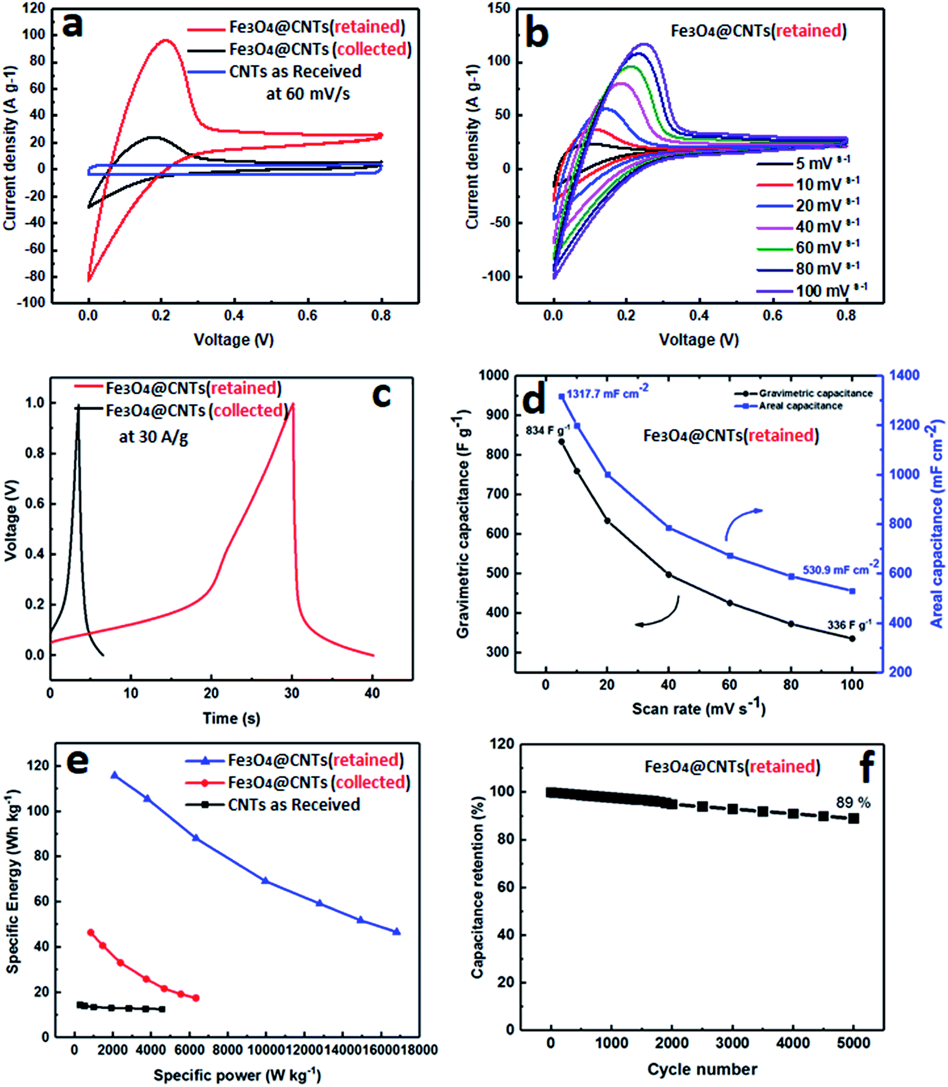 | ||
| Fig. 7 (a) Cyclic Voltammogram (CV) curves of MWCNTs (as received), Fe3O4@MWCNT (retained) and Fe3O4@MWCNTs (collected) at 60 mV s−1, (b) CV curves of Fe3O4@MWCNT (collected) at different scan rates from 5 to 100 mV s−1 and (c) charge–discharge curves of Fe3O4@MWCNT (retained and collected), (d) gravimetric capacitance and areal capacitance values versus scanning rate calculated from the CV curves of the Fe3O4@MWCNT (retained). (e) Specific energy vs. specific power of Fe3O4@MWCNT (retained). (f) Cycle performance of the Fe3O4@MWCNT (retained). | ||
The charge/discharge (CD) curves of both Fe3O4@MWCNT (retained and collected) are shown in Fig. 7c, confirming the same behaviour as displayed in CV measurements, and that Fe3O4@MWCNT (retained) has a longer charge and discharge time than Fe3O4@MWCNTs (collected) with noticeable deviation from linearity. Fig. 7d shows the areal and gravimetric (Cwt) capacitances of the Fe3O4@MWCNTs (retained) at different scan rates, ranging from 10 to 100 mV s−1, which were calculated from the CV curves of eqn (S1) and (S2) in the ESI.† The Fe3O4@MWCNTs (retained) electrode delivers gravimetric of 834 F g−1 and areal capacitance of 1317.7 mF cm−2 at a scan rate of 10 mV s−1. The exceptionally high value of the areal capacitance of the Fe3O4@MWCNTs (retained) electrode (1317.7 mF cm−2), highlights potential advantages of these composite materials and the method which was used to prepare them. The areal capacitance achieved in the present study is considerably higher or comparable than the recently reported values when using composite carbon materials for supercapacitor, such as (GF–CNT@Fe2O3) (659.5 mF cm−2 at 5 mA cm−2),41 (Ni/GF/Fe2O3) (572 mF cm−2 at 1 mA cm−2),66 (rGO–PEDOT/PSS films) (448 mF cm−2 at 10 mV s−1),67 (H2SO4–PVA this electrolyte, find materials) (402 mF cm−2),68 (FeOOH–MWCNT) (0.58 F cm−2 at 100 mV s−1),69 (MN3O4–MWCNTs) (2.8 F cm−2 at 2 mV s−1),70 (CNT hydrogel film with PANI) (680 mF cm−2 at 1 mA cm−2),71 and (V2O3–MWCNT) (4.4 F cm−2 at 2 mV s−1).72Fig. 7e features the Ragone plot of the calculated specific energy and specific power based on the total mass of electroactive materials in the two electrodes. The Fe3O4@MWCNT (retained) electrode delivers a significant high specific energy of 115.84 W h kg−1 at specific power of 2085 W kg−1. However, it can only provide a specific energy of 46.68 W h kg−1 at a specific power of 16![[thin space (1/6-em)]](https://www.rsc.org/images/entities/char_2009.gif) 803.33 W kg−1. More interestingly, the cyclic durability of the Fe3O4@MWCNTs (retained), shown in Fig. 7f, establishes excellent cycling ability. The Fe3O4@MWCNT (retained) electrode was tested for 5000 charge–discharge cycles at a current density of 30 A g−1, retaining 89% of the initial capacitance, and thus establishing good cycling performance.
803.33 W kg−1. More interestingly, the cyclic durability of the Fe3O4@MWCNTs (retained), shown in Fig. 7f, establishes excellent cycling ability. The Fe3O4@MWCNT (retained) electrode was tested for 5000 charge–discharge cycles at a current density of 30 A g−1, retaining 89% of the initial capacitance, and thus establishing good cycling performance.
4. Conclusion
We report a simple and effective method for decorating MWCNTs with superparamagnetic magnetite (Fe3O4) NPs using the VFD thin film microfluidic platform. The main advantages of the processing include that it is a focused three in one process, involving slicing the MWCNTs, generating the magnetite nanoparticles in situ, and the decoration of the MWCNTs. Both the slicing and the generation of the magnetite nanoparticles features the use of a pulsed laser operating at 1064 nm. This dual field effect application of the VFD adds to the versatility of the device, extending its field effect capabilities, with others including plasma processing and continuous light sources.73,74The generation of Fe3O4@MWCNT directly from pristine MWCNTs avoids the use of harsh chemicals while dramatically reducing the processing time, all of which are important in developing any applications. To this end, we have demonstrated the utility of the composite material retained in the VFD tube, in a high performing supercapacitor. The nanocomposite material (retained), resulted in a high areal capacitance (1317.7 mF cm−2) which is much larger than reported for other Fe3O4@CNTs electrodes.
Author contributions
All authors have given approval to the final version of the manuscript.Conflicts of interest
The authors declare no competing financial interest.Acknowledgements
T. M. D. A. would like to thank Taibah University (Ministry of Education, Saudi Arabia) for funding his scholarship. The authors also thank the Australian Research Council, The Government of South Australia, Adelaide Microscopy and AMMRF for support of this work.References
- H. Jiang, P. S. Lee and C. Li, Energy Environ. Sci., 2013, 6, 41–53 RSC.
- F. Ran, X. Yang and L. Shao, Advanced Composites and Hybrid Materials., 2018, 1, 32–55 CrossRef.
- Z. Yang, J. Ren, Z. Zhang, X. Chen, G. Guan, L. Qiu, Y. Zhang and H. Peng, Chem. Rev., 2015, 115, 5159–5223 CrossRef CAS PubMed.
- L. L. Zhang and X. S. Zhao, Chem. Soc. Rev., 2009, 38, 2520–2531 RSC.
- L. L. Zhang, R. Zhou and X. S. Zhao, J. Mater. Chem., 2010, 20, 5983–5992 RSC.
- Y. Huang, J. Liang and Y. Chen, Small, 2012, 8, 1805–1834 CrossRef CAS PubMed.
- Q. Liao, N. Li, S. Jin, G. Yang and C. Wang, ACS Nano, 2015, 9, 5310–5317 CrossRef CAS PubMed.
- L. Yuan, X.-H. Lu, X. Xiao, T. Zhai, J. Dai, F. Zhang, B. Hu, X. Wang, L. Gong, J. Chen, C. Hu, Y. Tong, J. Zhou and Z. Wang, ACS Nano, 2011, 6, 656–661 CrossRef PubMed.
- Z. Chen, V. Augustyn, J. Wen, Y. Zhang, M. Shen, B. Dunn and Y. Lu, Adv. Mater., 2011, 23, 791–795 CrossRef CAS PubMed.
- P.-C. Chen, G. Shen, Y. Shi, H. Chen and C. Zhou, ACS Nano, 2010, 4, 4403–4411 CrossRef CAS PubMed.
- Y. Zhao, W. Ran, J. He, Y. Huang, Z. Liu, W. Liu, Y. Tang, L. Zhang, D. Gao and F. Gao, Small, 2015, 11, 1310–1319 CrossRef CAS PubMed.
- S. G. Mohamed, C.-J. Chen, C. K. Chen, S.-F. Hu and R.-S. Liu, ACS Appl. Mater. Interfaces, 2014, 6, 22701–22708 CrossRef CAS PubMed.
- J. Chang, M. Jin, F. Yao, T. H. Kim, V. T. Le, H. Yue, F. Gunes, B. Li, A. Ghosh, S. Xie and Y. H. Lee, Adv. Funct. Mater., 2013, 23, 5074–5083 CrossRef CAS.
- C. X. Guo and C. M. Li, Energy Environ. Sci., 2011, 4, 4504–4507 RSC.
- A. L. M. Reddy and S. Ramaprabhu, J. Phys. Chem. C, 2007, 111, 7727–7734 CrossRef CAS.
- M. Zhi, C. Xiang, J. Li, M. Li and N. Wu, Nanoscale, 2013, 5, 72–88 RSC.
- J. Tucek, K. C. Kemp, K. S. Kim and R. Zboril, ACS Nano, 2014, 8, 7571–7612 CrossRef CAS PubMed.
- H.-S. Kim, H. Lee, K.-S. Han, J.-H. Kim, M.-S. Song, M.-S. Park, J.-Y. Lee, J.-K. Kang and J.-K. Kang, J. Phys. Chem. B, 2005, 109, 8983–8986 CrossRef CAS PubMed.
- X. J. Liu, I. Marangon, G. Melinte, C. Wilhelm, C. Menard-Moyon, B. P. Pichon, O. Ersen, K. Aubertin, W. Baaziz, C. Pham-Huu, S. Begin-Colin, A. Bianco, F. Gazeau and D. Begin, ACS Nano, 2014, 8, 11290–11304 CrossRef CAS PubMed.
- A. Star, V. Joshi, S. Skarupo, D. Thomas and J.-C. P. Gabriel, J. Phys. Chem. B, 2006, 110, 21014–21020 CrossRef CAS PubMed.
- G.-W. Yang, G.-Y. Gao, C. Wang, C.-L. Xu and H.-L. Li, Carbon, 2008, 46, 747–752 CrossRef CAS.
- Q. Liu, W. Ren, Z.-G. Chen, B. Liu, B. Yu, F. Li, H. Cong and H.-M. Cheng, Carbon, 2008, 46, 1417–1423 CrossRef CAS.
- S. Y. Lee, W. C. Choi, C. Jeon, C.-Y. Park, J. H. Yang and M. H. Kwon, Appl. Phys. Lett., 2008, 93, 103101 CrossRef.
- M. Liebau, E. Unger, G. Duesberg, A. Graham, R. Seidel, F. Kreupl and W. Hoenlein, Appl. Phys. A, 2003, 77, 731–734 CrossRef CAS.
- P. C. Ma, B. Z. Tang and J.-K. Kim, Carbon, 2008, 46, 1497–1505 CrossRef CAS.
- J. Deng, X. Wen and Q. Wang, Mater. Res. Bull., 2012, 47, 3369–3376 CrossRef CAS.
- D. Guan, Z. Gao, W. Yang, J. Wang, Y. Yuan, B. Wang, M. Zhang and L. Liu, Mater. Sci. Eng., B, 2013, 178, 736–743 CrossRef CAS.
- Y. Chen and H. Gu, Mater. Lett., 2012, 67, 49–51 CrossRef CAS.
- S. J. Henley, S. Mollah, C. E. Giusca and S. R. P. Silva, J. Appl. Phys., 2009, 106, 064309 CrossRef.
- Z. Sun, Z. Li, C. Huang, Y. Zhao, H. Zhang, R. Tao and Z. Liu, Carbon, 2011, 49, 4376–4384 CrossRef CAS.
- H. Zhou, C. Zhang, H. Li and Z. Du, J. Polym. Sci., Part A: Polym. Chem., 2010, 48, 4697–4703 CrossRef CAS.
- M. Morales, O. Bomati-Miguel, R. P. De Alejo, J. Ruiz-Cabello, S. Veintemillas-Verdaguer and K. O'Grady, J. Magn. Magn. Mater., 2003, 266, 102–109 CrossRef CAS.
- J. C. Tristao, A. A. Oliveira, J. D. Ardisson, A. Dias and R. M. Lago, Mater. Res. Bull., 2011, 46, 748–754 CrossRef CAS.
- J. Freedman, D. Mattia, G. Korneva, Y. Gogotsi, G. Friedman and A. K. Fontecchio, Appl. Phys. Lett., 2007, 90, 103108 CrossRef.
- R. Singhal, Z. Orynbayeva, R. V. K. Sundaram, J. J. Niu, S. Bhattacharyya, E. A. Vitol, M. G. Schrlau, E. S. Papazoglou, G. Friedman and Y. Gogotsi, Nat. Nanotechnol., 2011, 6, 57 CrossRef CAS PubMed.
- B. Šljukić, C. E. Banks and R. G. Compton, Nano Lett., 2006, 6, 1556–1558 CrossRef PubMed.
- W. Kim, J. S. Lee and J. Jang, RSC Adv., 2018, 8, 31874–31880 RSC.
- X. Luo, A. H. Al-Antaki, T. M. Alharbi, W. D. Hutchison, Y.-c. Zou, J. Zou, A. Sheehan, W. Zhang and C. L. Raston, ACS Omega, 2018, 3, 11172–11178 CrossRef CAS PubMed.
- A. H. M. Al-antaki, X. Luo, A. Duan, R. N. Lamb, E. Eroglu, W. Hutchison, Y.-C. Zou, J. Zou and C. L. Raston, RSC Adv., 2018, 8, 40829–40835 RSC.
- K. Vimalanathan, J. R. Gascooke, I. Suarez-Martinez, N. A. Marks, H. Kumari, C. J. Garvey, J. L. Atwood, W. D. Lawrance and C. L. Raston, Sci. Rep., 2016, 6, 22865 CrossRef CAS PubMed.
- C. Guan, J. Liu, Y. Wang, L. Mao, Z. Fan, Z. Shen, H. Zhang and J. Wang, ACS Nano, 2015, 9, 5198–5207 CrossRef CAS PubMed.
- S. F. Chin, K. S. Iyer and C. L. Raston, Lab Chip, 2008, 8, 439–442 RSC.
- T. M. Alharbi, K. Vimalanathan, W. D. Lawrance and C. L. Raston, Carbon, 2018, 140, 428–432 CrossRef CAS.
- X. Chen, J. F. Dobson and C. L. Raston, Chem. Commun., 2012, 48, 3703–3705 RSC.
- T. M. Alharbi, D. Harvey, I. K. Alsulami, N. Dehbari, X. Duan, R. N. Lamb, W. D. Lawrance and C. L. Raston, Carbon, 2018, 137, 419–424 CrossRef CAS.
- Y. A. Goh, X. Chen, F. M. Yasin, P. K. Eggers, R. A. Boulos, X. Wang, H. T. Chua and C. L. Raston, Chem. Commun., 2013, 49, 5171–5173 RSC.
- F. M. Yasin, R. A. Boulos, B. Y. Hong, A. Cornejo, K. S. Iyer, L. Gao, H. T. Chua and C. L. Raston, Chem. Commun., 2012, 48, 10102–10104 RSC.
- X. Luo, A. H. M. Al-Antaki, K. Vimalanathan, J. Moffatt, K. Zheng, Y.-C. Zou, J. Zou, X. Duan, R. Lamb and S. Wang, React. Chem. Eng., 2018, 3, 164–170 RSC.
- K. Vimalanathan, R. G. Shrestha, Z. Zhang, J. Zou, T. Nakayama and C. L. Raston, Angew. Chem., Int. Ed., 2017, 56, 8398–8401 CrossRef CAS PubMed.
- L. Yasmin, X. Chen, K. A. Stubbs and C. L. Raston, Sci. Rep., 2013, 3, 2282 CrossRef PubMed.
- T. Z. Yuan, C. F. G. Ormonde, S. T. Kudlacek, S. Kunche, J. N. Smith, W. A. Brown, K. M. Pugliese, T. J. Olsen, M. Iftikhar and C. L. Raston, ChemBioChem, 2015, 16, 393–396 CrossRef CAS PubMed.
- J. Britton, L. M. Meneghini, C. L. Raston and G. A. Weiss, Angew. Chem., 2016, 128, 11559–11563 CrossRef.
- J. Britton, C. L. Raston and G. A. Weiss, Chem. Commun., 2016, 52, 10159–10162 RSC.
- J. Britton, K. A. Stubbs, G. A. Weiss and C. L. Raston, Chem.–Eur. J., 2017, 23, 13270–13278 CrossRef CAS PubMed.
- K. Vimalanathan and C. L. Raston, Adv. Mater. Technol., 2017, 2, 1600298 CrossRef.
- M. Muruganathan, H. Mizuta and R. Sundara, Nano Lett., 2018, 18, 5688–5696 CrossRef PubMed.
- X. Jia, W. Li, X. Xu, W. Li, Q. Cai and X. Yang, ACS Appl. Mater. Interfaces, 2015, 7, 3170–3179 CrossRef CAS PubMed.
- M. Hao, M. Tang, W. Wang, M. Tian, L. Zhang and Y. Lu, Composites, Part B, 2016, 95, 395–403 CrossRef CAS.
- J. O. Marques Neto, C. R. Bellato, C. H. de Souza, R. C. d. Silva and P. A. Rocha, J. Braz. Chem. Soc., 2017, 28, 2301–2312 CAS.
- H. Chen, Z. Zhang, X. Wang, J. Chen, C. Xu, Y. Liu, Z. Yu and X. Wang, ACS Appl. Nano Mater., 2018, 1, 2386–2396 CrossRef CAS.
- T. Okpalugo, P. Papakonstantinou, H. Murphy, J. McLaughlin and N. Brown, Carbon, 2005, 43, 153–161 CrossRef CAS.
- L. Liu, J. Lang, P. Zhang, B. Hu and X. Yan, ACS Appl. Mater. Interfaces, 2016, 8, 9335–9344 CrossRef CAS PubMed.
- J. Wu and L. Kong, Appl. Phys. Lett., 2004, 84, 4956–4958 CrossRef CAS.
- C. Huiqun, Z. Meifang and L. Yaogang, J. Solid State Chem., 2006, 179, 1208–1213 CrossRef.
- W. Zhao, L. Zhu, Y. Lu, L. Zhang, R. H. Schuster and W. Wang, Synth. Met., 2013, 169, 59–63 CrossRef CAS.
- K. Chi, Z. Zhang, Q. Lv, C. Xie, J. Xiao, F. Xiao and S. Wang, ACS Appl. Mater. Interfaces, 2017, 9, 6044–6053 CrossRef CAS PubMed.
- Y. Liu, B. Weng, J. M. Razal, Q. Xu, C. Zhao, Y. Hou, S. Seyedin, R. Jalili, G. G. Wallace and J. J. S. r. Chen, Sci. Rep., 2015, 5, 17045 CrossRef CAS PubMed.
- Y. Xu, Z. Lin, X. Huang, Y. Liu, Y. Huang and X. Duan, ACS Nano, 2013, 7, 4042–4049 CrossRef CAS PubMed.
- R. Chen, I. K. Puri and I. Zhitomirsky, Ceram. Int., 2018, 44, 18007–18015 CrossRef CAS.
- M. Ata, J. Milne and I. Zhitomirsky, J. Colloid Interface Sci., 2018, 512, 758–766 CrossRef CAS PubMed.
- S. Zeng, H. Chen, F. Cai, Y. Kang, M. Chen and Q. Li, J. Mater. Chem. A, 2015, 3, 23864–23870 RSC.
- C. Wallar, R. Poon and I. Zhitomirsky, J. Electrochem. Soc., 2017, 164, A3620–A3627 CrossRef CAS.
- D. B. Jones, X. Chen, A. Sibley, J. S. Quinton, C. J. Shearer, C. T. Gibson and C. L. Raston, Chem. Commun., 2016, 52, 10755–10758 RSC.
- L. A. Ho, C. L. Raston and K. A. Stubbs, Chem.–Eur. J., 2018, 24, 8869–8874 CrossRef CAS PubMed.
Footnote |
| † Electronic supplementary information (ESI) available: Additional information on controlling experiments and optimizing conditions for fabricating composites of multi-walled carbon nanotubes (MWCNTs) and superparamagnetic magnetite nanoparticles. See DOI: 10.1039/c9na00346k |
| This journal is © The Royal Society of Chemistry 2019 |