
 Open Access Article
 This Open Access Article is licensed under a Creative Commons Attribution-Non Commercial 3.0 Unported Licence
Stress-transfer from polymer substrates to monolayer and few-layer graphenes†
Ch.
Androulidakis
 a,
D.
Sourlantzis
b,
E. N.
Koukaras
ac,
A. C.
Manikas
b and
C.
Galiotis
*ab
a,
D.
Sourlantzis
b,
E. N.
Koukaras
ac,
A. C.
Manikas
b and
C.
Galiotis
*ab
aInstitute of Chemical Engineering Sciences, Foundation of Research and Technology-Hellas (FORTH/ICE-HT), Stadiou Street, Platani, Patras, 26504 Greece. E-mail: c.galiotis@iceht.forth.gr; galiotis@chemeng.upatras.gr
bDepartment of Chemical Engineering, University of Patras, Patras, 26504 Greece
cLaboratory of Quantum and Computational Chemistry, Department of Chemistry, Aristotle University of Thessaloniki, GR-54124 Thessaloniki, Greece
First published on 5th November 2019
Abstract
In the present study, the stress transfer mechanism in graphene–polymer systems under tension is examined experimentally using the technique of laser Raman microscopy. We discuss in detail the effect of graphene edge geometry, lateral size and thickness which need to be taken under consideration when using graphene as a protective layer. The systems examined were composed of graphene flakes with a large length (over ∼50 microns) and a thickness of one to three layers simply deposited onto PMMA substrates which were then loaded to a tension of ∼1.60% strain. The stress transfer profiles were found to be linear while the results show that large lateral sizes of over twenty microns are needed in order to provide effective reinforcement at levels of strain higher than 1%. Moreover, the stress built up has been found to be quite sensitive to both edge shape and geometry of the loaded flakes. Finally, the transfer lengths were found to increase with the increase of graphene layers. The outcomes of the present study provide crucial insight into the issue of stress transfer from polymers to graphene nano-inclusions as a function of edge geometry, lateral size and thickness in a number of applications.
1. Introduction
Graphitic materials in various forms such as carbon fibres (CFs), carbon nanotubes (CNTs) and graphene (Gr) exhibit remarkable mechanical properties, such as high moduli up to ∼1 TPa (ref. 1–4) and tensile strengths up to ∼100 GPa,1 which can be put into good use in composites employing polymers,2 ceramics3 and even metal matrices.4 In the case of CF/polymer composites there is already a dearth of commercial applications in the aerospace, automotive, household, and recreational sectors which have sprung up over the last 30 years due to the unique combination of mechanical properties per unit mass that they can offer. CNTs and graphene have also been examined recently as nano-fillers in polymer matrices as they can provide moderate enhancement in modulus and strength at small loadings in combination with a significant increase of thermal and electrical conductivities of the host matrices.5,6 Graphene in particular offers certain advantages over CNTs as it can be handled much more easily and its high surface area makes it more effective as a potential filler for engineering polymers.7,8 Moreover, recent studies have shown that single and few layer graphenes are very effective for reinforcing metals such as nickel and palladium due to the strong interfacial bonding that is developed between these two classes of materials.4,9 Besides its use as a reinforcing filler, graphene is used as a coating in conventional materials for inducing multi-functionality.10 Various graphene coating applications have been demonstrated such as gilding of large structures4 and protection from corrosion.11For producing graphene/polymer composites even at low volume fractions, methods for scalable synthesis of graphene, such as shear liquid exfoliation,12,13 which yield relatively large quantities of multi-layer graphene flakes need to be employed. In fact, in a recent paper,14 it has been shown that the commercially available graphene with scalable production consists of few-layers of a lateral size of only a few microns. Furthermore, in most cases, the resulting graphene flakes are of small size (∼3 to 5 μm) and irregular shape. It is therefore clear that the size, thickness and shape of the flakes employed can play a critical role in the reinforcing capabilities of the filler.15,16 Despite the extensive use of these few-layer graphenes in nano-composites, there is very limited experimental work on the corresponding stress transfer mechanisms17 and particularly the required characteristics for efficient reinforcing capabilities.
The effective use and design of graphene as a reinforcing agent lies on the understanding of the interfacial behaviour of the graphene/matrix system. The mechanical load is transferred from the polymer to the graphitic inclusion by the interfacial shear, which is described by the well-known shear-lag mechanism in composite materials.18,19 The stress builds up from the edge and increases towards the inner part until it reaches the maximum value at some distance away from the edge which is usually termed as the transfer length (lt) (Fig. 1). The critical flake length (lc) will then be the minimum value required for the total stress build up and is defined as lc = 2lt.
 | ||
| Fig. 1 Schematic of the stress-transfer shear mechanism in the graphene/polymer system. For a large length of graphene, the applied strain to the matrix is fully transmitted to the graphene. The length required for the strain build-up is the transfer length (lt) and the required critical length (lc) of the flake for efficient reinforcement is lc = 2lt. | ||
The stress transfer mechanism of single layer graphene simply supported on polymers like PMMA20 and PET21,22 under tension has already been examined. The transfer length from previous studies was found to be in the range of 4–10 microns.16–18 These values were obtained from flakes of relatively small length (∼15 μm or less), and as will be shown later on, this is not the actual case since the transfer length is strain dependent. The shear-lag effect holds for small strain levels after which the strain is transferred through friction with a constant interface shear stress (ISS), until interface failure results in sliding of the graphene and no further transfer of mechanical stress is then possible.22 The ISS has been reported to be in the range of 0.40–0.80 MPa for graphene–polymer systems by converting the Raman data to strain maps and by considering the balance of shear-to-axial forces at the interface.17,20,22,23 These values are relatively low and methods to increase them have been proposed by the group in their previous work, such as the creation of a wrinkled interface which significantly enhances the stress transfer efficiency from the polymer to graphene16 or the introduction of artificial ‘defects’ into the filler which enhance the anchoring of graphene to the host polymer.24 Moreover, chemical modification of the polymer–graphene interface has proven to be effective in increasing the ISS.25
In order to estimate the values of the ISS, the strain profile and build-up from the edges of the graphene towards the inner part need to be captured as seen in Fig. 1.20,22 In this regard, Raman spectroscopy has been proven to be the most efficient method; the Raman peaks shift with the application of mechanical load26 and by monitoring the shift rates of the peaks (2D27 and G28), the level of stain in the graphene can be back-tracked in a straightforward manner.20,22 Raman maps can be taken for the 2D and G phonons across graphene flakes at small steps, even at the sub-micron level, providing high resolution for the strain distribution in graphene.20 The Raman maps are converted to values of strain based on the average shift rate which has been examined in numerous studies to be in the range of ∼50 to 64 cm−1/% for the 2D peak.20,27,29,30 As mentioned earlier, having established the strain build-up, the ISS can be obtained by a simple balance of axial-to-shear-force argument.20
Despite the recent extensive efforts to exploit graphene as a reinforcing filler in polymers, the stress transfer characteristics have been studied in a handful of studies only on monolayer graphene/polymer systems whereas studies of few-layer graphene deposited or embedded in polymers are scarce.17,31 This is indeed a problem for engineering applications of graphene composites as most mass exfoliation techniques yield distributions of flakes of various thicknesses and lateral sizes. Moreover, as mentioned above, graphene is used as a coating material for large surfaces and thus, a comprehensive investigation of interfacial interactions with graphene of various thicknesses on a substrate is of crucial importance. Herein, we examine the stress-transfer mechanism of large graphene flakes with a length of >50 microns for a thickness of one to three layers simply supported on engineering polymers, such as PMMA, using the methodology presented above. Various aspects that have not received attention in previous studies such as the effect of the graphene geometry on the ISS and the implications of the stress transfer through friction on the transfer length are highlighted. The present work provides significant guidelines and in-depth understanding for the effective use of graphene in strain engineering applications and as a protective coating.
2. Experimental section
Graphene flakes were prepared in a clean room by mechanical exfoliation of highly ordered pyrolytic graphite (HOPG) using the Scotch tape method.32 The exfoliated graphitic materials were deposited directly on the surface of the SU-8/PMMA substrate. In Fig. 2 the optical images of the examined graphene flakes are presented. The SU-8 photoresist [Microchem 2000.5] was spin coated on the surface of the PMMA bar with a speed of ∼4000 rpm, resulting in a very thin layer of ∼180 to 200 nm thickness. Curing of SU-8 was performed in three steps: pre-bake, UV exposure and post-bake treatment. Appropriate graphene flakes were located with an optical microscope and the exact thickness was identified from the line-shape of the 2D Raman peak. A four-point bending apparatus was adjusted under the Raman microscope for simultaneously loading the specimens under tension and for recording the Raman spectra (785 nm excitation). The laser power was kept below ∼1 mW to avoid local heating of the specimens. External strain was applied in a stepwise manner by bending of the polymer bar at increases of ∼0.1% and the 2D Raman peak was acquired in situ. At every strain level, the whole graphene flake was scanned from edge to edge at steps of ∼1 μm and Raman spectra were continuously recorded. The magnitude of strain on the top surface of the PMMA bar where graphene was located was estimated by beam deflection and also by means of electrical resistance strain gauges.15,16,20 | ||
| Fig. 2 Optical images of the examined graphene flakes with thicknesses of (a) one layer (b), two layers and (c) three layers. All the flakes are relatively large and with ribbon type geometry. The yellow dotted lines denote the shape of the flakes and the geometry of the edges with respect to the tensile direction. The scale bar is 10 microns. | ||
3. Results and discussion
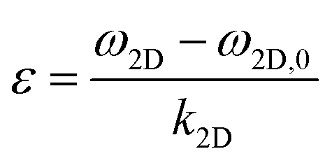
In Fig. 2a, an optical image of the examined single layer graphene is presented. The flake is relatively large with a length of ∼60 microns and has a micro-ribbon geometry. It is important to note that the right edge is almost perfectly vertical and normal to the tensile direction while the left edge is tapered at an angle of ∼32 degrees with respect to the horizontal axis (Fig. 2a).To measure accurately the Raman wavenumber shift for the monolayer graphene, we ensure that the data were collected from the middle of the flake for which the stress/strain distribution vs. distance from the edges forms a plateau. Evidently, measurements of small flakes can be problematic as the lateral size may be smaller than the critical length (see further comments below). Here, the specimen was subjected to a tension of up to ∼1.60% strain and the average shift of the 2D peak was found to be ∼ −47.4 ± 2 cm−1/%, which is somewhat lower from the expected value of ∼−55 cm−1/% for a laser line of 785 nm.27 The actual strain in the graphene can be obtained using the following equation:20
 | (1) |
 | (2) |
 | ||
| Fig. 3 (a) Average shift of the 2D peak of the single layer graphene of the specimen examined here. (b) Representative strain distributions across the length of graphene for selected levels of strain. The strain is derived by converting the spectroscopic data to values of strain. Until 0.56%, the left angle indicates the presence of axial strain transmission as noted by the shaded grey area. (c) The interfacial shear stress (ISS) estimated from eqn (2) for the left (angular) and right (aligned normal to the tensile direction) edges of the flake by linear fit of the strain build-up. (d) Expanding the fitting lines of the strain build-up until convergence. The top value of the formation of the triangle corresponds to the maximum strain that the graphene can reach before slipping from the substrate. It is interesting to note that no fracture is observed up to 1.6% strain which was the upper limit of strain applied on graphene in the experimental setup. | ||
 | ||
| Fig. 4 The distribution of the ISS across the length of the single layer graphene for ∼1.60% tension. | ||
 | ||
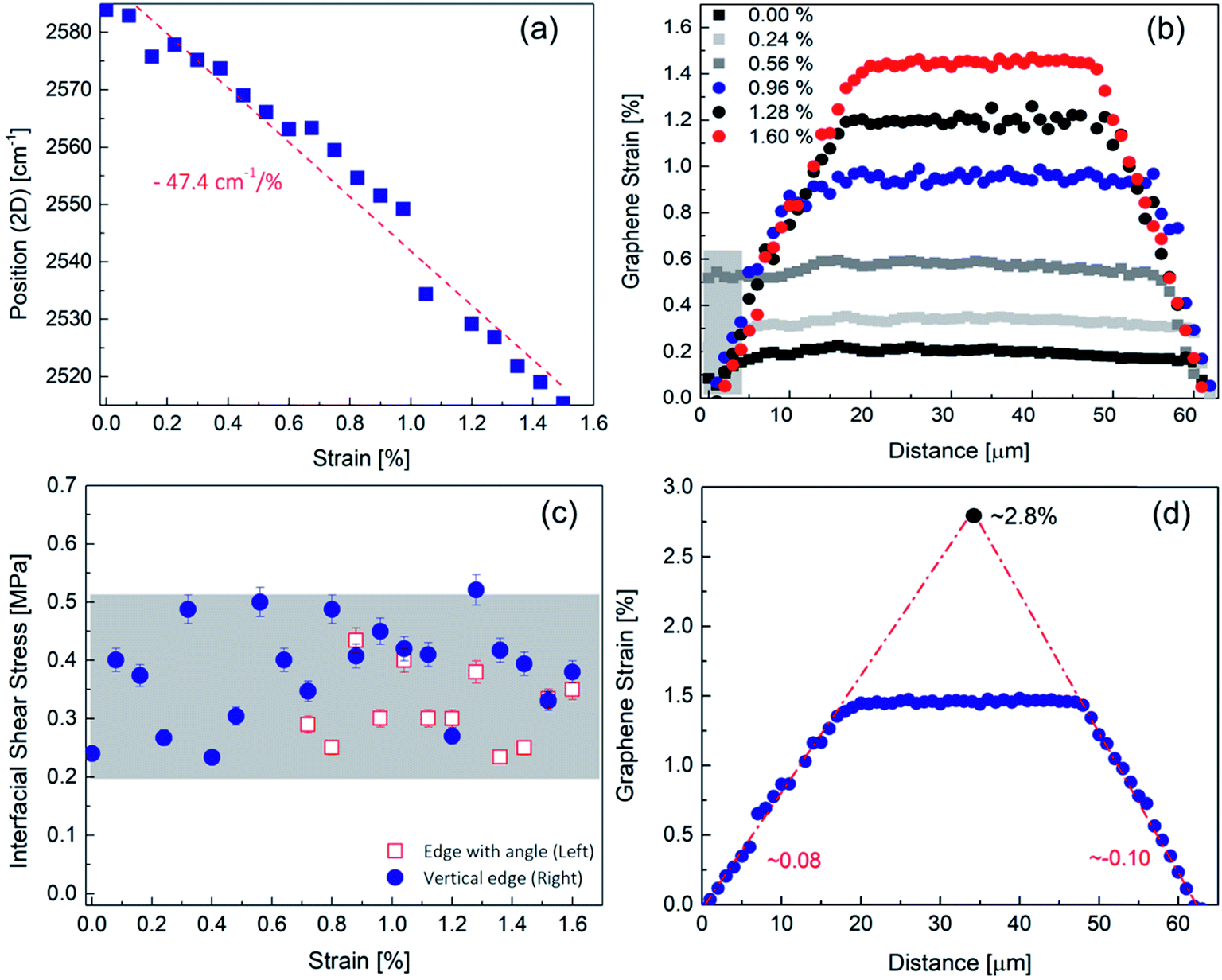
| Fig. 5 The average shift of the 2D peak which has been estimated based on the mid areas to avoid edge effects for (a) bilayer and (c) trilayer flakes, respectively.20 Representative strain distributions across the length of graphene for selected levels of strain for (b) the bilayer and (d) trilayer flakes, respectively. | ||
We can observe that the strain build-up is not the same for both edges, which indicates that the edge shape affects the ISS values. This is a significant point which has not received significant attention in previous studies. The build-up from the square edge normal to the applied stress follows the shearing mechanism and can be approximated with very good accuracy with linear fits, which indicates that the friction like mechanism is prevalent in the as-supported graphene/PMMA composite. It is interesting to note that very similar strain transfer profiles have been obtained in composite systems, such as in fibre/metal composites, for which the fibres are weakly bonded to the matrix.34 Furthermore, the group in their previous work has shown that linear profiles are also observed in untreated (and unsized) carbon fibre/epoxy systems35 whereas, in contrast, oxidised carbon fibres embedded in epoxy matrices exhibit quite pronounced shear lag behaviour in which the absolute value of the strain derivative of eqn (2) in the transfer length region is not a constant value but decays abruptly as one moves towards the centre of the fibre.35,36 Furthermore, the clear build-up from the very edges indicates no interface slippage between graphene and the polymer, since the Raman peak positions shift with the applied strain.
The strain built up profiles from the angular edge also show a quite complex behaviour. For small strains, a built-up from the edge toward the middle of the flake is observed but for higher strains, it seems that there is an axial transmission of stress (strain) rather than a shear generated stress (strain) transfer (Fig. 1b). The reasons for the axial transmission are not quite clear but it is not inconceivable that the angular edge has been embedded or bonded into the resin due to the transfer process, allowing axial transmission. From the Raman shift, we measure a maximum stress of 5 GPa for an applied strain of 0.56% and considering the angle of the edge, we obtain ∼4.3 GPa acting on the normal face of graphene. We must note that this is a rough estimation since the distribution of the normal stress is not constant throughout the edge area and changes with the applied strain as seen in Fig. 3b. This effect has been shown and examined elsewhere in detail by FEM simulations in a similar system.37 At applied strains of ∼1% or even higher, the axial transmission is lost possibly to the debonding of the flake angular edge and then a shear mechanism prevails. The fact that the graphene strain now builds in a linear fashion from a zero value at the edge confirms the above assertion. Finally, it is worth noting that no fracture or interface failure is observed up to 1.60% strain which was the upper limit applied on graphene in the experimental setup. This is quite significant since the overall loaded area is of the order of ∼60 × 8 = 480 μm2 which is much larger than that in any such experiments reported earlier by us20 or others23 and shows once more than the crystal perfection of graphene is retained at much higher length scales than envisaged earlier.
In Fig. 4 the ISS profile across the length of the single layer graphene for the maximum tensile strain is presented and that for various selected levels of strain is given in the ESI.† The maximum ISS occurs at the very edges of the graphene flakes, which indicates the absence of doping at the edges.20 As expected the ISS values (particularly in the case of the ‘square’ end) are of a constant value and of the opposite sign from each flake edge. For increasing tension, the length required for reaching zero ISS increases too, and for the ‘square’ end, it is about ∼10 μm at the maximum applied tensile strain of 1.6%. All ISS values from both ends (for the case of shear transfer) are presented in Fig. 3c. As seen, the ISS values as a function of the applied strain form a plateau – within the experimental error – with a mean value of ∼0.39 MPa for the square end and ∼0.31 MPa for the angular edge, respectively. The average ISS and the shift rate obtained herein are somewhat lower than previously reported values of 0.45 MPa (ref. 20) and ∼−55 cm−1/% (ref. 27) for the same polymer substrate and for same preparation procedure. This small deviation is within the experimental error and thus acceptable and stems from slight differences in the experimental conditions such as sample preparation and mechanical experiments. It is therefore evident that the shape of the graphene inclusions needs to be taken into consideration for the best exploitation of graphene as a reinforcing agent in composites. In the middle of the graphene, a remarkably constant strain distribution occurs. Due to the large length of the flake, this can be clearly observed even for a high level of the applied tension. Moreover, as presented elsewhere,38 the ribbon type geometry of the flake employed here prevents the formation of wrinkling induced by the Poisson contraction of the polymer38 due to its small width.15
Another crucial point when using graphitic fillers in polymers is the length of the inclusion required for efficient reinforcement of the polymer.18,39,40 In general, this length is ten times the transfer length obtained by the shear-lag model, and is estimated as the length required for reaching ∼90% of the maximum strain;23 however this analysis is not entirely correct since the transfer length is strain dependent and the level of applied external strain needs to be taken into account. As the results of Fig. 3d clearly show by extrapolation, the monolayer graphene flake can be efficiently loaded at its geometric middle up to an external applied tensile strain with maximum value of 2.80% beyond which it will start lagging behind the applied strain. At this level of strain, if slippage has not initiated, the required critical length (twice the transfer length) is as large as ∼60 μm. This value is already much larger than the average commercial flake size41 and thus it transpires that for a polymer matrix to transfer stress to, say, a simply-supported monolayer graphene, a critical length of at least 10 μm is required (Fig. 3b) to achieve strains as low as ∼0.5%. This may be quite acceptable for structural composites but it may be a problem for certain functional applications. However it must be stressed that as has been shown earlier, for fully embedded flakes, the transfer lengths have been found to be much smaller than the values reported here for simply-supported flakes.15
We turn our attention now to the stress transfer characteristics of bi and tri-layer graphene–polymer composites. Graphene flakes of large length (>50 μm) and small width were chosen and the corresponding optical images are shown in Fig. 2b and c. In this case, almost all edges were fairly square and as will be argued below, shear at the interface was again the main stress transfer mechanism. In the ESI,† we also present results for another bilayer with both edges of angular shape, which shows axial transmittance for both edges and the strain transfer characteristics show certain differences from those presented below. Thus, one can conclude that the edge geometry plays a crucial role in the reinforcing capacity of graphene.
Before we move forward to further discussion of the results of the few-layer flakes, we need to thoroughly consider the validity of eqn (2) for this case. The derivation of eqn (2) assumes a material of thickness t and Young's modulus E and a particular Raman shift rate. When interlayer slippage occurs, eqn (2) which is based on load transfer through shear at the graphene/polymer interface cannot be applied. As the onset of interlayer slippage is hard to detect, eqn (2) cannot be safely employed in this work to deduct the values of interfacial shear stress. Moreover, it has been found that the adhesion energy of a graphene–substrate interface decreases with increase in graphene thickness;42 thus we cannot assume that the ISS for the few layers would be the same with that of the single layer, although this can be tested in future work. It is expected that if the graphene was stretched as a whole unit, as for example, in the case of hexagonal boron nitride as shown recently,43 the ISS would be identical for all flakes without layer number dependence where a value of 0.30 MPa was estimated. However, for the current experiments, we can use the slopes of wavenumber shifts per increment of strain as a comparative measure of load transfer as they reflect accurately the stress take-up by the multilayer graphenes.
The average shift rate of the 2D peak is ∼−43.7 ± 2 cm−1/% and ∼−44 ± 2 cm−1/% for the bi and tri-layer flakes, respectively. As pointed out for the case of a single layer, the area for the extraction of the shift rate plays a pivotal role. For the bilayer, again the shift is obtained from the central area that exhibits a constant strain profile up to ∼1.50%. For the trilayer, we can obtain the shift from the plateau area up to ∼1%, but for higher strains, the critical length is larger than the lateral flake length so the measurements are inaccurate. These values are slightly smaller than the shift of the single layer but they are in broad agreement with earlier findings.16 Still, the above values are much higher than those obtained in the past from flakes that were smaller in size than the required critical length for maximum stress transfer.20 Thus, multiple layers can achieve high shift rates having sufficiently large length, but still they are lacking compared to the single layers. Moreover, the good alignment with the loading direction also contributes to this large shift as discussed below. In Fig. 5b and e representative strain profiles for selected levels of tension are introduced in order to present the behaviour for the whole examined tensile regime. For both flakes, the results appear similar to those obtained in the case of monolayer graphene albeit at much higher transfer lengths.
We observe for the bilayer a convex shape at the right edge which we attribute to its angular shape (Fig. 2b), since the same feature in the strain transfer mechanism was observed for another bilayer with geometrically angular edges (see the ESI†). For the initial levels of strain until ∼0.60%, the strain profile fluctuates and becomes smooth as the tension increases. A second built-up occurs at a distance of ∼10 microns from the left edge, which is a result of the loss of stacking and interlayer relative slippage which creates a discontinuity in the multi-layer structure as observed optically previously.44 The loss of stacking is clearly demonstrated from the line-shape of the 2D (Fig. S6†) peak for both the examined few-layer flakes and is in agreement with previous results.45
The stress transfer behaviour of the tri-layer is very similar to that of the bi-layer. Again, we observe problematic build-up for the right edge where axial transmittance occurs (Fig. 5e). For a tension of ∼0.80% where the strain profile is smooth along the length of the graphene, the shear mechanism is the same friction-like one as discussed for the mono and bilayer flakes. Local discontinuities in the strain build-up are also present for the trilayer (Fig. 5e), which are plausibly due to the loss of stacking (see the ESI† for the 2D peak line-shape) as in the case of the bilayer. More results for the trilayer flake are given in the ESI.†
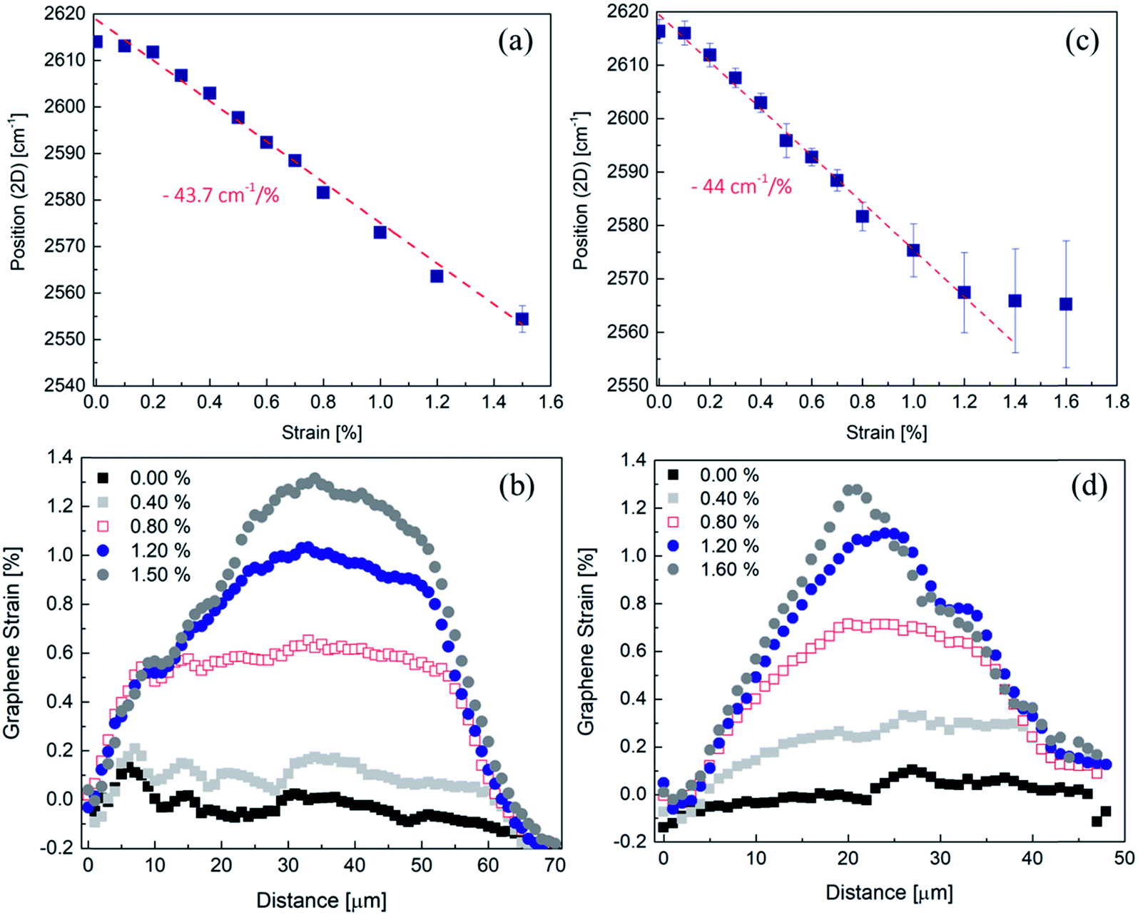
The bilayer of ∼70 microns in length can reach a critical strain for slippage of ∼1.90%, while for the trilayer (see above) this critical point has already been reached at ∼1.30% and the interface cannot support any higher stresses/strains (Fig. 6a). For these strain levels, the transfer lengths are of the order of ∼15 to 22 μm for the bilayer which is approximately twice the values obtained for monolayer graphene with square ends at a similar strain (Fig. 3b). For the tri-layer, the maximum tensile strain has indeed been reached ∼1.30% (Fig. 6a). This is also clearly depicted in the deviation of the 2D shift rate which shows no further downshift of the position of the peak after ∼1.20% tension (Fig. 5d) since the transfer length required for higher tension has overcome the length of the graphene, in contrast to the bilayer which could be stretched to higher strains. A tri-layer of ∼50 microns in length can be stretched up to a maximum tension of ∼1.20% when supported on a polymer, while the transfer length at ∼1.20% is ∼22 to 30 microns, depending on the edge as shown in Fig. 6a. Again, the single layer is beneficial in this regard too, as it needs a much smaller length for reaching the same strain compared to a few-layer material. The above results clearly demonstrate that while the same level of interfacial shear can be developed between graphene and the polymer, the few-layer graphenes are still lacking compared to the single layer, due to the inefficient interlayer stress transfer between the individual graphene layers.16,31 In cases that graphene needs to reach higher deformations, it is apparent from previous analysis that graphene flakes with a length of a few-tens of microns are required, and this length increases for the bilayer and trilayer flakes.
 | ||
| Fig. 6 (a) Expanding the fitting lines of the strain build-up until convergence for the examined bilayer (grey circles) and trilayer (black rectangles) graphenes. The top value of the formation of the triangle corresponds to the maximum strain that the graphene can reach before slipping from the substrate. The bilayer could reach a tensile strain of ∼1.90% while the trilayer has already reached its maximum strain. (b) The average values of the slopes obtained from the strain profiles for all flakes and the whole tensile regime. For the single layer, the slopes obtained from both edges are plotted. | ||
In Fig. 6b, the slopes of dε/dx are plotted versus the number of layers of graphene for all examined tensile strain levels. In Fig. 6b the values obtained from both edges for the case of the monolayer are plotted, which show a small decrease for the angular edge compared to the square edge as discussed above. We observe from Fig. 6b that the slopes for the few-layers are strain dependent and increase almost linearly with the tensile strain until a maximum value is reached. However, the actual values for both bilayer and trilayer are markedly lower than the corresponding shifts of the monolayer for the same strain. This is a direct consequence of the stress transfer process as expressed by the balance-of-forces argument (eqn (2)), since for the same interfacial shear stress, a thicker material of the same stiffness cannot be stressed by the same amount. The increase of slopes with strain was not expected in view of the onset of interlayer slippage but it may be due to the gradual offset of the compressive residual stresses of the as-prepared specimens. Over approximately 0.5–0.6% strain, the slopes form a plateau but still, in spite of the expected interlayer slippage, the system can take up considerable stresses (strains). Overall, the results obtained here suggest that while the graphene thickness increases, much larger lateral sizes are required for efficient reinforcement in the case of commercially produced flakes which exhibit a quite broad distribution of lateral sizes typically of smaller size than those measured here.
In summary, we examined the stress transfer mechanism in simply supported graphene–polymer systems with thicknesses of one to three layers. The results clearly show that single layer graphene is more effective as a reinforcement agent in polymers in terms of dimensions, since a much smaller length is required compared to few layers for effective reinforcement. We redefined the graphene length required for efficient reinforcement based on the stress transfer through a constant ISS which is found to be strain dependent and estimated that much higher values are actually needed in order to fully exploit the potential of graphene. Graphene flakes with lengths of tens of microns are required for ensuring reinforcing capacity from a polymer substrate to the as-supported graphenes at large deformations and the lateral size increases with the increase of graphene thickness. The results also reveal that square edges with the applied load are more efficient and lead to a higher ISS compared to angular and random shaped graphene flakes. The present study provides an in-depth investigation and design guidance when using graphene of random shape and thickness, which is commonly produced by large scale production methods.
Conflicts of interest
There are no conflicts to declare.Acknowledgements
CG acknowledges the support from “Graphene Core 2, GA: 696656” which is implemented under the EU-Horizon 2020 Research & Innovation Actions (RIA) and is financially supported by EC-financed parts of the Graphene Flagship. The authors acknowledge the financial support from the European Research Council (ERC Advanced Grant 2013) via project no. 321124, “Tailor Graphene”. E. N. K. acknowledges the funding for this project from the Hellenic Foundation for Research and Innovation (HFRI) and the General Secretariat for Research and Technology (GSRT), under grant agreement No 1536. CG and AM acknowledge support from the Open FET project “Development of continuous two-dimensional defect-free materials by liquid-metal catalytic routes” no. 736299-LMCat which is implemented under the EU-Horizon 2020 Research Executive Agency (REA) and is financially supported by EC.References
- C. Lee, X. Wei, J. W. Kysar and J. Hone, Measurement of the Elastic Properties and Intrinsic Strength of Monolayer Graphene, Science, 2008, 321(5887), 385–388 CrossRef CAS PubMed.
- B. Sreenivasulu, B. Ramji and M. Nagaral, A Review on Graphene Reinforced Polymer Matrix Composites, Mater. Today: Proc., 2018, 5(1), 2419–2428 CAS.
- H. Porwal, S. Grasso and M. Reece, Review of Graphene–Ceramic Matrix Composites, Adv. Appl. Ceram., 2013, 112(8), 443–454 CrossRef CAS.
- K. Zhang, C. Androulidakis, M. Chen and S. Tawfick, Gilding with Graphene: Rapid Chemical Vapor Deposition Synthesis of Graphene on Thin Metal Leaves, Adv. Funct. Mater., 2018, 28(48), 1804068 CrossRef.
- Z. Spitalsky, D. Tasis, K. Papagelis and C. Galiotis, Carbon Nanotube–Polymer Composites: Chemistry, Processing, Mechanical and Electrical Properties, Prog. Polym. Sci., 2010, 35(3), 357–401 CrossRef CAS.
- S. Stankovich, D. A. Dikin, G. H. Dommett, K. M. Kohlhaas, E. J. Zimney, E. A. Stach, R. D. Piner, S. T. Nguyen and R. S. Ruoff, Graphene-Based Composite Materials, Nature, 2006, 442(7100), 282 CrossRef CAS PubMed.
- P. Liu, Z. Jin, G. Katsukis, L. W. Drahushuk, S. Shimizu, C.-J. Shih, E. D. Wetzel, J. K. Taggart-Scarff, B. Qing and K. J. Van Vliet, Layered and Scrolled Nanocomposites with Aligned Semi-Infinite Graphene Inclusions at the Platelet Limit, Science, 2016, 353(6297), 364–367 CrossRef CAS PubMed.
- I. Vlassiouk, G. Polizos, R. Cooper, I. Ivanov, J. K. Keum, F. Paulauskas, P. Datskos and S. Smirnov, Strong and Electrically Conductive Graphene-Based Composite Fibers and Laminates, ACS Appl. Mater. Interfaces, 2015, 7(20), 10702–10709 CrossRef CAS PubMed.
- K. Zhang, M. Poss, P. J. Chen and S. Tawfick, Strengthening Nickel by in Situ Graphene Synthesis, Adv. Eng. Mater., 2017, 19(12), 1700475 CrossRef.
- L. Tan, C. Wang, M. Zeng and L. Fu, Graphene: An Outstanding Multifunctional Coating for Conventional Materials, Small, 2017, 13(13), 1603337 CrossRef PubMed.
- A. Krishnamurthy, V. Gadhamshetty, R. Mukherjee, B. Natarajan, O. Eksik, S. A. Shojaee, D. A. Lucca, W. Ren, H.-M. Cheng and N. Koratkar, Superiority of Graphene over Polymer Coatings for Prevention of Microbially Induced Corrosion, Sci. Rep., 2015, 5, 13858 CrossRef PubMed.
- K. R. Paton, E. Varrla, C. Backes, R. J. Smith, U. Khan, A. O'Neill, C. Boland, M. Lotya, O. M. Istrate and P. King, Scalable Production of Large Quantities of Defect-Free Few-Layer Graphene by Shear Exfoliation in Liquids, Nat. Mater., 2014, 13(6), 624 CrossRef CAS PubMed.
- A. Amiri, M. Naraghi, G. Ahmadi, M. Soleymaniha and M. Shanbedi, A Review on Liquid-Phase Exfoliation for Scalable Production of Pure Graphene, Wrinkled, Crumpled and Functionalized Graphene and Challenges, FlatChem, 2018, 8, 40–71 CrossRef CAS.
- A. Kovtun, E. Treossi, N. Mirotta, A. Scidà, A. Liscio, M. Christian, F. Valorosi, A. Boschi, R. J. Young and C. Galiotis, Benchmarking of Graphene-Based Materials: Real Commercial Products Vs. Ideal Graphene, 2D Mater., 2019, 6, 025006 CrossRef CAS.
- C. Androulidakis, E. N. Koukaras, O. Frank, G. Tsoukleri, D. Sfyris, J. Parthenios, N. Pugno, K. Papagelis, K. S. Novoselov and C. Galiotis, Failure Processes in Embedded Monolayer Graphene under Axial Compression, Sci. Rep., 2014, 4, 5271 CrossRef PubMed.
- C. Androulidakis, E. N. Koukaras, J. Rahova, K. Sampathkumar, J. Parthenios, K. Papagelis, O. Frank and C. Galiotis, Wrinkled Few-Layer Graphene as Highly Efficient Load Bearer, ACS Appl. Mater. Interfaces, 2017, 9(31), 26593–26601 CrossRef CAS PubMed.
- C. Androulidakis, K. Zhang, M. Robertson and S. Tawfick, Tailoring the Mechanical Properties of 2d Materials and Heterostructures, 2D Mater., 2018, 5(3), 032005 CrossRef.
- J. A. Nairn, On the Use of Shear-Lag Methods for Analysis of Stress Transfer in Unidirectional Composites, Mech. Mater., 1997, 26(2), 63–80 CrossRef.
- A. Weerasinghe, C.-T. Lu, D. Maroudas and A. Ramasubramaniam, Multiscale Shear-Lag Analysis of Stiffness Enhancement in Polymer–Graphene Nanocomposites, ACS Appl. Mater. Interfaces, 2017, 9(27), 23092–23098 CrossRef CAS PubMed.
- G. Anagnostopoulos, C. Androulidakis, E. N. Koukaras, G. Tsoukleri, I. Polyzos, J. Parthenios, K. Papagelis and C. Galiotis, Stress Transfer Mechanisms at the Submicron Level for Graphene/Polymer Systems, ACS Appl. Mater. Interfaces, 2015, 7(7), 4216–4223 CrossRef CAS PubMed.
- C. Xu, T. Xue, W. Qiu and Y. Kang, Size Effect of the Interfacial Mechanical Behavior of Graphene on a Stretchable Substrate, ACS Appl. Mater. Interfaces, 2016, 8(40), 27099–27106 CrossRef CAS PubMed.
- T. Jiang, R. Huang and Y. Zhu, Interfacial Sliding and Buckling of Monolayer Graphene on a Stretchable Substrate, Adv. Funct. Mater., 2014, 24(3), 396–402 CrossRef CAS.
- L. Gong, I. A. Kinloch, R. J. Young, I. Riaz, R. Jalil and K. S. Novoselov, Interfacial Stress Transfer in a Graphene Monolayer Nanocomposite, Adv. Mater., 2010, 22(24), 2694–2697 CrossRef CAS PubMed.
- G. Anagnostopoulos, L. Sygellou, G. Paterakis, I. Polyzos, C. A. Aggelopoulos and C. Galiotis, Enhancing the Adhesion of Graphene to Polymer Substrates by Controlled Defect Formation, Nanotechnology, 2018, 30(1), 015704 CrossRef PubMed.
- G. Wang, Z. Dai, L. Liu, H. Hu, Q. Dai and Z. Zhang, Tuning the Interfacial Mechanical Behaviors of Monolayer Graphene/Pmma Nanocomposites, ACS Appl. Mater. Interfaces, 2016, 8(34), 22554–22562 CrossRef CAS PubMed.
- C. Androulidakis, E. N. Koukaras, J. Parthenios, G. Kalosakas, K. Papagelis and C. Galiotis, Graphene Flakes under Controlled Biaxial Deformation, Sci. Rep., 2015, 5, 18219 CrossRef CAS PubMed.
- C. Androulidakis, G. Tsoukleri, N. Koutroumanis, G. Gkikas, P. Pappas, J. Parthenios, K. Papagelis and C. Galiotis, Experimentally Derived Axial Stress–Strain Relations for Two-Dimensional Materials Such as Monolayer Graphene, Carbon, 2015, 81, 322–328 CrossRef CAS.
- O. Frank, G. Tsoukleri, I. Riaz, K. Papagelis, J. Parthenios, A. C. Ferrari, A. K. Geim, K. S. Novoselov and C. Galiotis, Development of a Universal Stress Sensor for Graphene and Carbon Fibres, Nat. Commun., 2011, 2, 255 CrossRef.
- T. Mohiuddin, A. Lombardo, R. Nair, A. Bonetti, G. Savini, R. Jalil, N. Bonini, D. Basko, C. Galiotis and N. Marzari, Uniaxial Strain in Graphene by Raman Spectroscopy: G Peak Splitting, Grüneisen Parameters, and Sample Orientation, Phys. Rev. B: Condens. Matter Mater. Phys., 2009, 79(20), 205433 CrossRef.
- G. Tsoukleri, J. Parthenios, K. Papagelis, R. Jalil, A. C. Ferrari, A. K. Geim, K. S. Novoselov and C. Galiotis, Subjecting a Graphene Monolayer to Tension and Compression, Small, 2009, 5(21), 2397–2402 CrossRef CAS PubMed.
- C. Androulidakis, E. Koukaras, M. Hadjinicolaou and C. Galiotis, Non-Eulerian Behavior of Graphitic Materials under Compression, Carbon, 2018, 138, 227–233 CrossRef CAS.
- K. S. Novoselov, A. K. Geim, S. V. Morozov, D. Jiang, Y. Zhang, S. V. Dubonos, I. V. Grigorieva and A. A. Firsov, Electric Field Effect in Atomically Thin Carbon Films, Science, 2004, 306(5696), 666–669 CrossRef CAS PubMed.
- O. Frank, M. Mohr, J. Maultzsch, C. Thomsen, I. Riaz, R. Jalil, K. S. Novoselov, G. Tsoukleri, J. Parthenios and K. Papagelis, Raman 2d-Band Splitting in Graphene: Theory and Experiment, ACS Nano, 2011, 5(3), 2231–2239 CrossRef CAS PubMed.
- A. Kelly and G. Davies, The Principles of the Fibre Reinforcement of Metals, Metall. Rev., 1965, 10(1), 1–77 CAS.
- N. Melanitis and C. Galiotis, Interfacial Micromechanics in Model Composites Using Laser Raman Spectroscopy, Proc. R. Soc. London, Ser. A, 1993, 440(1909), 379–398 CrossRef CAS.
- N. Melanitis, C. Galiotis, P. Tetlow and C. Davies, Interfacial Shear Stress Distribution in Model Composites: The Effect of Fibre Modulus, Composites, 1993, 24(6), 459–466 CrossRef CAS.
- G. Guo and Y. Zhu, Cohesive-Shear-Lag Modeling of Interfacial Stress Transfer between a Monolayer Graphene and a Polymer Substrate, J. Appl. Mech., 2015, 82(3), 031005 CrossRef.
- C. Androulidakis, E. Koukaras, M. P. Carbone, M. Hadjinicolaou and C. Galiotis, Wrinkling Formation in Simply-Supported Graphenes under Tension and Compression Loadings, Nanoscale, 2017, 9(46), 18180–18188 RSC.
- Y. Termonia, Theoretical Study of the Stress Transfer in Single Fibre Composites, J. Mater. Sci., 1987, 22(2), 504–508 CrossRef CAS.
- C. Galiotis, Interfacial Studies on Model Composites by Laser Raman Spectroscopy, Compos. Sci. Technol., 1991, 42(1–3), 125–150 CrossRef CAS.
- A. Kovtun, E. Treossi, N. Mirotta, A. Scida, A. Liscio, M. Christian, F. Valorosi, A. Boschi, R. J. Young and C. Galiotis, Benchmarking of Graphene-Based Materials: Real Commercial Products Vs. Ideal Graphene, 2D Mater., 2019, 6, 025006 CrossRef CAS.
- S. P. Koenig, N. G. Boddeti, M. L. Dunn and J. S. Bunch, Ultrastrong Adhesion of Graphene Membranes, Nat. Nanotechnol., 2011, 6(9), 543 CrossRef CAS PubMed.
- C. Androulidakis, E. Koukaras, M. Poss, K. Papagelis, C. Galiotis and S. Tawfick, Strained Hexagonal Boron Nitride: Phonon Shift and Grüneisen Parameter, Phys. Rev. B: Condens. Matter Mater. Phys., 2018, 97(24), 241414 CrossRef CAS.
- L. Gong, R. J. Young, I. A. Kinloch, S. J. Haigh, J. H. Warner, J. A. Hinks, Z. Xu, L. Li, F. Ding and I. Riaz, Reversible Loss of Bernal Stacking During the Deformation of Few-Layer Graphene in Nanocomposites, ACS Nano, 2013, 7(8), 7287–7294 CrossRef CAS PubMed.
- O. Frank, M. Bouša, I. Riaz, R. Jalil, K. S. Novoselov, G. Tsoukleri, J. Parthenios, L. Kavan, K. Papagelis and C. Galiotis, Phonon and Structural Changes in Deformed Bernal Stacked Bilayer Graphene, Nano Lett., 2011, 12(2), 687–693 CrossRef PubMed.
Footnote |
| † Electronic supplementary information (ESI) available. See DOI: 10.1039/c9na00323a |
| This journal is © The Royal Society of Chemistry 2019 |